
How Veneer Walls Carry Loads, Drain Water and Avoid Failure
Compare anchored and adhered systems, trace gravity and lateral load paths, and understand how cavities, flashing, weeps and movement joints prevent failure.
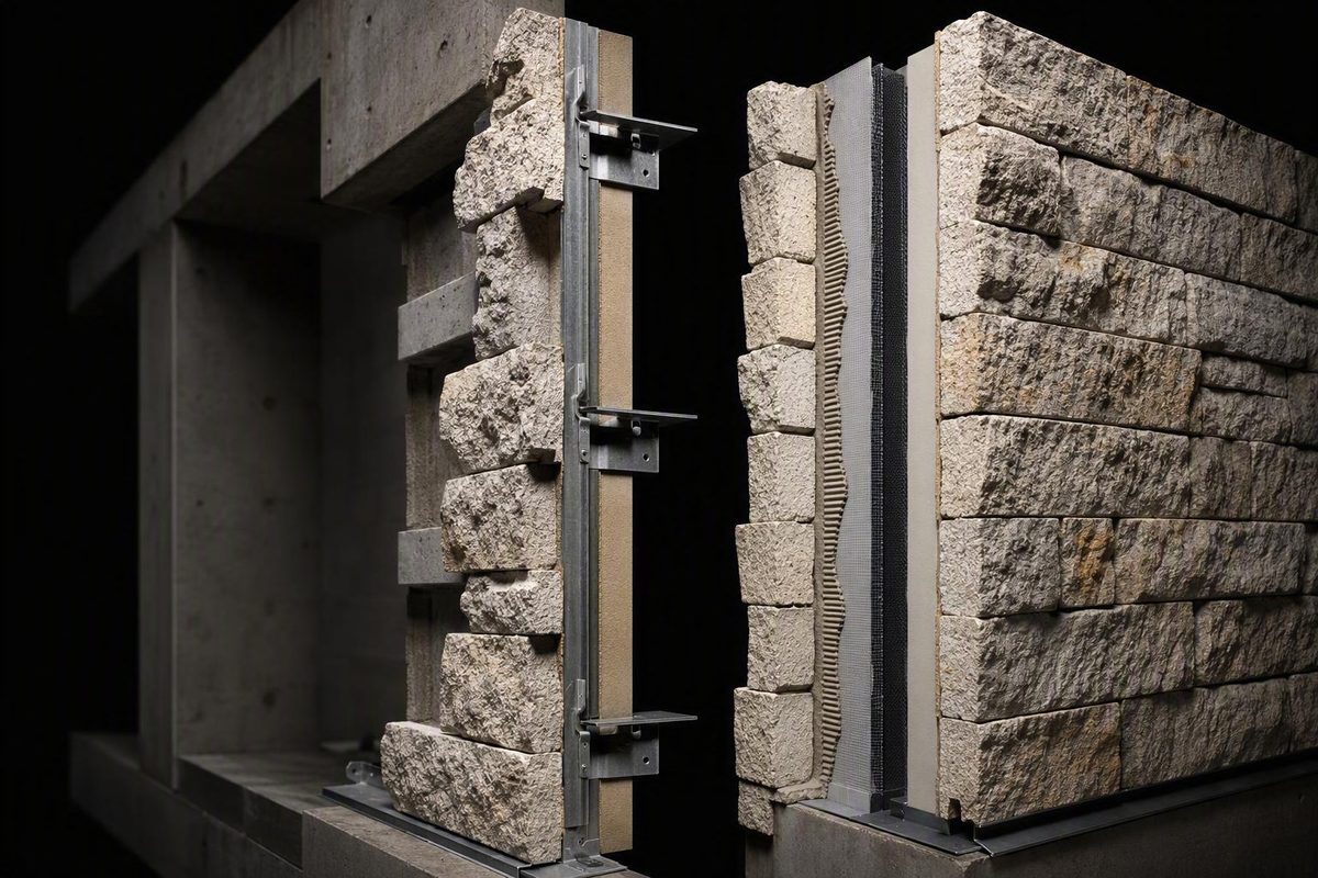
Masonry veneer is easy to misunderstand because the most visible part of the wall is not the part carrying most of the building’s structural or environmental work. Brick, stone, concrete masonry or thin facing may dominate the elevation, but its performance depends on the backup structure, attachment system, control layers, drainage path, supports, movement joints and interfaces behind it.
The central design question is not simply, “Which masonry looks right?” It is, “How will the complete assembly carry forces, drain penetrating rain, accommodate movement and remain inspectable and repairable?”
This overview explains those relationships without providing project-specific calculations. Mandatory requirements come from the locally adopted building code, the applicable edition of TMS 402/602, local amendments, approved product information and the project’s construction documents. Recommendations from industry guides or manufacturers should not be treated as code provisions unless the governing documents make them applicable.
What masonry veneer is—and what “nonstructural” really means
Masonry veneer is a masonry facing that transfers out-of-plane loads to a structural backing but is not credited with adding strength or stiffness to the wall system. Common materials include brick, concrete masonry products, natural stone, manufactured stone and thin brick. Common backups include wood framing, steel studs, concrete masonry units and concrete. This division between facing and backing is described in the Concrete Masonry & Hardscapes Association’s veneer guidance.
“Nonstructural” does not mean decorative, weightless or unsupported. Veneer must carry its own weight and resist applicable wind, seismic and other out-of-plane forces. Depending on the system, those forces travel through foundations, shelf angles, lintels, ties, anchors, bond coats, lath and fasteners before reaching the primary structure.
A structural masonry wall is different because its masonry participates in carrying building loads. In a veneer wall, the separate backup structure carries the building’s primary loads, while the veneer and its connections follow defined gravity and lateral load paths of their own.
Thickness alone does not determine whether masonry is veneer. A relatively thick stone facing can still be veneer when it transfers out-of-plane forces to a backing and is not counted as part of the wall’s primary structural resistance. Conversely, a masonry wythe may be structural when it is designed and constructed to carry building loads.
Terminology
- Wythe: A continuous vertical layer of masonry one unit thick.
- Backup wall: Framed, concrete or masonry construction behind the veneer that provides structural support.
- Cavity: The space between the veneer and the backup or exterior insulation, commonly used for drainage and sometimes ventilation.
- Tie: A connector that transfers lateral force between anchored veneer and its backing.
- Anchor: A general term for a connection to the backup; some assemblies use multi-part adjustable anchors with separate veneer ties.
- Flashing: Water-impervious material that intercepts water within the wall and directs it outdoors.
- Weep: An outlet that allows collected water to leave an anchored-veneer cavity.
- WRB: Water-resistive barrier; the layer that limits liquid-water entry into water-sensitive construction behind the drainage space.
- Shelf angle: A structural ledge that provides gravity support to a section of anchored veneer.
- Weep screed: A termination and drainage outlet commonly used at the bottom of an adhered veneer assembly.
The distinction matters in drawings and specifications. Calling a wall “brick” or “stone” does not establish who supports its weight, how wind forces reach the structure or how penetrating rain exits. Those responsibilities must be shown explicitly.
Anchored versus adhered veneer: two different load paths
Anchored and adhered masonry veneer may look nearly identical from the street, but they transfer forces and manage water differently.
Anchored veneer is connected to the backup primarily through ties or anchors. It normally stands away from the backup or exterior insulation, leaving an open drainage cavity. Its dead load bears on a foundation, shelf angle, lintel or another designed structural support. Wind and other out-of-plane loads pass from the masonry through ties or anchors into the backup.
Adhered veneer is bonded to a suitable substrate, either directly or through an assembly that may include setting mortar, a scratch coat, metal lath and mechanical fasteners. Its load path can include the veneer-to-mortar bond, reinforced mortar or lath, fasteners, sheathing or another substrate, framing and connections to the primary structure. It generally does not use the shelf-support arrangement typical of multistory anchored veneer.
That distinction makes substrate condition especially important for adhered work.
| Decision factor | Anchored veneer | Adhered veneer |
|---|---|---|
| Veneer material and weight | Often accommodates full-depth units; gravity support must be defined | Often uses thinner units; weight must suit the approved bond and attachment assembly |
| Primary lateral transfer | Ties or adjustable anchors to the backup | Bond, lath and fasteners, or direct bond to an approved substrate |
| Gravity support | Foundation, shelf angle, lintel or other structural support | Attachment and bond to the substrate |
| Drainage strategy | Commonly uses an open cavity | May use a thinner drainage plane, furring layer or drainage mat |
| Backup | Wood, steel, CMU or concrete with compatible anchors | Framing, masonry, concrete or a cementitious substrate approved for the assembly |
| Building height | Intermediate supports and movement relief may become important | Height may be limited by prescriptive provisions or assembly approvals |
| Wind and seismic exposure | Affect tie type, spacing, capacity and backup demand | Affect bond, lath, fasteners, substrate and framing demand |
| Substrate stiffness | Influences anchor response and wall serviceability | Critical to bond integrity and cracking control |
| Freeze-thaw exposure | Affects units, mortar, flashing and retained moisture | Affects units, mortar or adhesive, bond and drainage |
| Installation access | Cavity and anchors become concealed as work rises | WRB, drainage, lath, fasteners and bond surfaces become concealed |
| Repair implications | May involve ties, supports, flashing or local rebuilding | May involve bond investigation, substrate repair and local or broader removal |
These are tendencies, not interchangeable specifications. A thin unit can be mechanically anchored, and an adhered product can be part of a proprietary drained assembly. Appearance does not identify the load path.
Selection should begin with the adopted code and proposed backup, then proceed through applicable evaluation reports, approved assembly information and manufacturer instructions. Unit weight and geometry, height, wind and seismic exposure, substrate stiffness, climate, drainage and access all matter.
Anatomy of a complete veneer wall
A masonry-veneer wall is a stack of components with separate jobs. Performance improves when drawings identify each job instead of assigning everything vaguely to “weatherproofing.”
Anchored veneer concept: outside to inside
The following schematic is conceptual rather than dimensional:
EXTERIOR
   Rain
    ↓
[1 Masonry facing]
    │ lateral force → [2 Ties or anchors] → structural backup
    │ penetrating water
    ↓
[3 Clear drainage cavity]
    ↓
[4 Through-wall flashing] → [5 Weeps and drip edge] → OUT
    │
[6 Exterior insulation, where used]
[7 WRB / air-control layer]
[8 Sheathing or masonry backup]
[9 Framing, CMU or concrete]
    │
    ↓ primary structure
INTERIOR

Gravity path:
Masonry facing ↓ foundation / lintel / shelf angle

Movement:
Vertical veneer joints + coordinated backup joints
Horizontal relief below supported veneer where required
The numbered components perform these functions:
- Masonry facing: Sheds most rain and provides the visible finish.
- Ties or anchors: Transfer out-of-plane loads into the backup.
- Clear cavity: Gives penetrating water a route downward.
- Through-wall flashing: Intercepts water at the cavity base and other interruptions.
- Weeps and drip edge: Discharge water and reduce return beneath the flashing.
- Exterior insulation, where used: Provides thermal resistance without blocking drainage or interfering with anchors.
- WRB and air-control layer: Limit liquid-water entry and airflow; one product performs both functions only when designed and detailed for both.
- Sheathing or masonry backup: Supports attachments and contributes to structural resistance.
- Framing, CMU or concrete: Carries primary building loads and veneer reactions.
Foundations, shelf angles and lintels provide gravity support where required. Expansion, control and relieving joints accommodate differential movement. The International Masonry Institute’s anchored brick base detail shows how a CMU backup, above-grade barrier, continuous insulation, supported flashing, weeps, a drip edge and coordinated movement joints can meet at a critical transition.
Adhered veneer concept: outside to inside
EXTERIOR
   Rain
    ↓
[1 Veneer units]
[2 Setting mortar or approved adhesive]
[3 Scratch coat, where applicable]
[4 Lath and fasteners OR approved direct-bond substrate]
    │ load → substrate → framing / solid backup
[5 Drainage mat or drainage plane, where included]
    ↓
[6 Weep screed or approved outlet] → OUT
[7 WRB]
[8 Sheathing]
[9 Framing or solid backup]
    │
    ↓ primary structure
INTERIOR

Movement:
Sealant or separation joints at changes in substrate,
geometry, support and material
Not every adhered assembly contains every listed component. Some systems bond directly to concrete or masonry; others use cement board, lath or proprietary drainage components. The applicable evaluation report, tested assembly and manufacturer instructions determine the actual sequence.
Adhered veneer is supported through its connection to the substrate rather than by the weep screed. Where lath is used, correct material, orientation, laps, fastening and mortar encapsulation are part of the load path.
Control layers are not interchangeable
Several layers may occupy the same plane or be combined in one product, but their functions remain distinct:
- The water-shedding surface rejects most bulk rain.
- The drainage layer gives penetrating water a route down and out.
- The WRB limits liquid-water entry into the backup.
- The air barrier controls airflow through the enclosure.
- The insulation controls heat flow.
- The vapor-control layer, where required by the assembly, limits vapor diffusion.
Masonry contributes thermal mass but relatively little insulation by itself. Thermal performance comes mainly from insulation continuity, air sealing, thermal-bridge control and the moisture condition of the complete assembly.
Continuity must survive actual building geometry. At foundations, the above-grade WRB must connect to base flashing and the below-grade water-control system. At windows and doors, sill, jamb and head membranes must return into the wall’s drainage plane. At floor lines, shelf angles and penetrations, insulation and air barriers need deliberate transitions.
A collection of individually credible products is not necessarily a credible wall. Proprietary components should be evaluated as part of an approved assembly rather than mixed solely because each product works independently.
How masonry veneer manages rain
Exterior masonry should not be treated as waterproof. A drainage assembly anticipates some penetration through units, joints and small cracks, then collects and directs that water outdoors before it reaches vulnerable construction.
In an anchored wall, water reaching the back of the veneer descends through the clear cavity. It lands on flashing, moves toward the exterior and exits through weeps. In a drained adhered assembly, water follows a thinner drainage plane or mat and exits at a weep screed or another approved termination.
The governing design commonly addresses flashing at:
- wall bases;
- window and door heads and sills;
- shelf angles or selected floor lines;
- parapets and copings;
- chimneys;
- roof-to-wall intersections;
- changes in wall depth or material;
- projections, penetrations and other interruptions.
Whether each location is mandatory depends on the adopted code, approved assembly and project documents. Industry guidance consistently treats these interruptions as points requiring deliberate drainage detailing.
End dams prevent collected water from running off the ends of sill or lintel flashing into the wall. Sloped sills move surface water away. Flashing extensions and drip edges carry drainage beyond the veneer face. The flashing’s inner edge must integrate with the WRB so water cannot pass behind it.
The clear path is as important as the materials. Mortar droppings can cover outlets or bridge the veneer to the backup. Debris can create dams. Discontinuous flashing may discharge into the wall rather than outside. Missing, buried or blocked outlets can leave water without an intended exit.
Why one cavity or weep dimension does not fit every wall
Published guidance varies because it addresses different backups, weep types, code editions and construction conditions.
CMHA guidance describes a 1-inch minimum air space for the anchored concrete-masonry veneer conditions it discusses and expresses a preference for 2 inches unless special precautions keep the narrower space clean. Its cited context also describes partially open head-joint weeps at least 1 inch high and spaced no more than 32 inches on center. These figures are conditional guidance, not universal dimensions, and must be checked against the currently governing provisions and project design. See the previously cited CMHA guidance.
A Glen-Gery brick design guide recommends clear air spaces of 2 inches at steel-stud backup, 1½ inches at reinforced-concrete or concrete-block backup, and 1 inch at wood-stud backup. The same guide recommends open-head-joint weeps at 24 inches on center and cotton-cord wick weeps at 16 inches on center. Its publication does not identify the editions of all referenced standards, so the values should be treated as manufacturer technical guidance rather than current nationwide code requirements. (Brickwork Design Profile)
A separate trade summary recommends weep spacing of 16 to 24 inches, but it does not state a governing code edition or cavity width. That range should therefore remain tied to the source’s residential brick-veneer context rather than blended with the CMHA values. (Pro Trade Craft water-management guidance)
These numbers are not a menu from which to choose the smallest value. The design should state the required clear, not merely nominal, cavity; the drainage accessory; flashing shape; outlet type and spacing; and applicable tolerances. The contractor must then be able to build and keep that space clear.
Worked example: the base of an anchored wall
A base detail can be reviewed in sequence:
- Maintain control-layer continuity. Connect the above-grade WRB or combined air/moisture barrier to the foundation water-control system.
- Support the flashing. Carry through-wall flashing across the cavity without creating a sagging trough that retains water.
- Turn the inner edge up and integrate it with the WRB. Water descending either plane should land on the flashing.
- Extend drainage to the exterior. Terminate at the face or at a compatible drip edge rather than leaving water to return beneath the masonry.
- Place outlets at the flashing level. The required weep type and spacing must follow the governing design.
- Protect the drainage zone. Keep mortar and debris from blocking outlets or bridging the cavity. Mortar-control accessories may be useful, but they are optional unless required by the selected assembly or project documents.
- Accommodate movement. Continue planned veneer joints and coordinate them with backup joints where the design requires.
- Coordinate grade and paving. Maintain the project-specified separation and direct surface water away from the wall.
- Show gravity support. Identify where the veneer bears and how flashing crosses or terminates at that support.
The same sequence—collect, support, turn up, integrate, discharge and keep clear—applies at openings, shelf angles and roof intersections, although the geometry changes.
Support, anchorage, movement and engineered-design triggers
Anchored veneer has two related structural paths. Gravity load travels to a foundation, shelf angle, lintel or another support. Out-of-plane load travels through corrosion-resistant ties or anchors into the backup. Both paths must remain reliable while the wall moves and becomes wet.
Backup type affects the connection. CMHA guidance identifies corrugated sheet-metal anchors as limited to wood backing, while steel and concrete backing use adjustable anchors in the conditions it discusses. This is not a universal product-selection rule: current governing provisions, anchor approvals, fastener engagement, cavity geometry and project calculations control.
A complete anchorage review considers:
- veneer unit size, depth and weight;
- design wind pressure and pressure zones;
- seismic design category and movement demands;
- tie or anchor capacity and stiffness;
- spacing and supported tributary area;
- fastener and substrate capacity;
- backup-wall deflection;
- cavity and insulation thickness;
- building height and intermediate support;
- corrosion exposure and material compatibility;
- tolerances and installation access.
Tie stiffness matters because a stiffer connector can attract more force rather than simply being “better.” Generic spacing copied from a standard detail is therefore not a substitute for a project-specific check.
Movement must be designed, not repaired afterward
Clay masonry, concrete masonry, concrete, wood and steel do not move identically. They respond differently to moisture, temperature, shrinkage, creep and structural deflection. Floor edges, lintels and shelf angles introduce additional movement.
Depending on the materials and design, accommodations may include:
- vertical expansion or control joints in the veneer;
- coordinated joints in a CMU backup;
- joints at changes in height, thickness, support or material;
- horizontal relieving joints below shelf angles;
- compatible sealants and backer materials;
- lintels designed with suitable stiffness;
- gaps kept free of mortar where movement is intended.
Joint locations cannot be chosen from elevation aesthetics alone. Corners, openings, long uninterrupted runs, offsets and support locations all affect where stress concentrates. Project-specific spacing belongs in the construction documents.
Prescriptive versus engineered design
Prescriptive provisions apply only within their stated limits. Once unit geometry, weight, attachment, pressure, height or another condition falls outside those limits, engineered design may be required rather than an improvised modification.
A 2026 IIBEC technical paper summarizing TMS 402/602-22 identifies possible engineered-design triggers that include noncompliant ties or components, excessive tie spacing, units outside prescribed dimensions or weights, anchored veneer above 75 psf wind pressure, and adhered veneer above 60 psf wind pressure. It describes the discussed prescriptive adhered provisions as limited to 60 feet above grade and 60 psf wind pressure, with unit-weight limits of 50 psf for anchored veneer and 30 psf for adhered veneer. The author states that the trigger list is not exhaustive. These values must not replace the adopted standard or be combined with thresholds from another edition. (IIBEC engineered-veneer paper)
Under the TMS 402/602-22 framework summarized in that paper, anchored dimension-stone veneer requires engineering because natural-stone properties vary and relevant characteristics require testing. Material identity alone does not establish compressive strength, durability, bond behavior or attachment capacity.
The project team should consult the adopted building code, applicable TMS 402/602 edition, local amendments, structural calculations, evaluation reports and approved construction documents. Engineering is not only a high-rise issue: unusual units, deep cavities, flexible backups, large openings, high local wind pressure or nonstandard attachments can take a lower wall outside prescriptive assumptions.
Material, backup and specification decisions
Material selection should be based on verified assembly properties, not appearance alone. Brick, concrete products, natural stone, manufactured stone and thin brick may all function as masonry veneer, but they do not automatically share attachment, moisture, movement or freeze-thaw requirements.
For each proposed veneer, establish:
- actual unit dimensions, thickness and weight;
- absorption and suitability for the exposure;
- freeze-thaw performance where relevant;
- anchored, adhered or proprietary attachment method;
- substrate and deflection requirements;
- cavity or drainage-plane design;
- compatible corner, sill, cap and trim units;
- mortar, adhesive and jointing requirements;
- movement-joint strategy;
- applicable test reports, evaluation reports and approvals.
Backup-wall implications
Wood framing provides direct fastener access but is moisture-sensitive and can be comparatively flexible. Attachment must engage the framing or other substrate required by the approved design, not merely whatever layer is easiest to reach. The WRB must remain continuous around penetrations.
Cold-formed steel studs require coordination of deflection, fastener selection, corrosion protection and thermal bridging. Exterior sheathing, insulation and anchor stand-off influence connection geometry.
CMU backup provides a comparatively stiff masonry substrate and can receive adjustable anchors through mortar joints or another designed attachment. Its control joints, reinforcement and air/moisture barrier must coordinate with veneer joints and flashing.
Concrete backup is also comparatively stiff, but anchor type, embedment, placement tolerances and surface preparation require coordination. Barrier continuity at floor edges and construction joints may remain difficult even where the structure is robust.
These are tendencies, not rankings. A well-detailed framed wall may outperform a poorly coordinated concrete wall, and a stiff backup does not correct missing flashing.
Additional questions for adhered veneer
Confirm early:
- What is the veneer’s installed weight?
- Can the framing, sheathing and fasteners carry the load with the required serviceability?
- Is the assembly direct-bonded, lath-and-scratch-coat or proprietary?
- What lath type, orientation, laps, corner treatment and fastener layout apply?
- What mortar or adhesive is approved for the unit and substrate?
- How does the WRB connect to the drainage plane and weep screed?
- Is the unit-and-mortar assembly suitable for expected wetting and freeze-thaw exposure?
- What limits apply to height, wind pressure and substrate type?
A sponsored Mason Contractors Association article reports thin-veneer weights ranging from 3 to 25 psf and describes an assembly extending approximately 3 to 5 inches from the substrate, which creates eccentric load. These are planning observations from that source, not universal limits; supplier data and project design govern. (Designing an Adhered Masonry Veneer)
Specifications should request applicable product specifications, cut sheets, test reports, evaluation reports, installation instructions, accessory details, warranties and physical samples. A mockup can establish coursing, color, joint profile, corners, penetrations, flashing terminations and workmanship expectations before repetitive work begins.
No veneer material is inherently cheaper, faster, more durable, more energy-efficient or lower-maintenance than another without comparable evidence and defined assumptions. Installed cost depends on structure, access, labor, supports, detailing and schedule. Durability depends on exposure, material properties, drainage and workmanship. Energy performance depends primarily on the complete enclosure.
Construction quality control before the wall is concealed
Many consequential veneer defects disappear from view as construction progresses. Inspection should therefore follow the installation sequence rather than wait for a finished elevation. The checklist below is a review framework; whether an item is mandatory depends on the adopted code, approved documents and selected assembly.
Phase 1: substrate acceptance
- Confirm that framing, CMU or concrete matches the approved drawings.
- Check that the substrate is sound, clean, sufficiently stiff and suitable for the selected system.
- Verify sheathing type, orientation, fastening and joint treatment.
- Confirm openings, penetrations, shelf angles, lintels and support elevations before masonry begins.
- Resolve out-of-tolerance surfaces rather than concealing errors with irregular cavities or bond thicknesses.
Phase 2: barriers and insulation
- Check WRB continuity at seams, corners, penetrations and transitions.
- Verify air-barrier connections at foundations, openings, roofs and floor lines.
- Confirm insulation type, thickness, attachment and joint treatment.
- Check that insulation does not obstruct flashing, outlets or required anchor geometry.
- Document compatibility among WRBs, tapes, primers, sealants, flashing, adhesives, insulation and metals.
Phase 3: flashing and drainage
- Compare flashing locations with the approved details.
- Check positive support, upturned inner legs and integration with the WRB.
- Confirm seams, corners and end dams are completed as specified.
- Verify exterior extensions or drip edges where shown.
- Check that weeps or weep screeds align with the drainage plane and remain open.
- Distinguish required components from optional mortar-control or drainage accessories.
An older residential inspection guide hosted by a Michigan municipality illustrates flashing integration, end dams, drainage material and weeps, but it is tied to the 2003 Michigan Residential Code and must not be treated as current nationwide authority. (Guide to Inspecting Residential Brick Veneer)
Phase 4A: anchored-veneer attachment
- Verify that anchor type matches the backup and approved cavity geometry.
- Check fastener type, embedment and attachment to the required structural member.
- Compare horizontal and vertical spacing with approved documents.
- Confirm corrosion resistance for the exposure.
- Check tie engagement and orientation as masonry rises.
- Measure the clear cavity after accounting for construction tolerances and mortar placement.
- Remove mortar bridges and droppings.
- Coordinate anchors with shelf angles, lintels, joints, insulation and flashing.
Phase 4B: adhered-veneer reinforcement and attachment
- Confirm WRB and drainage-plane integration before lath conceals it.
- Verify lath material, weight, orientation, laps and self-furring condition where specified.
- Check inside- and outside-corner treatment.
- Verify that fasteners engage the framing or substrate required by the approved assembly.
- Confirm fastener type, corrosion resistance, washers and layout.
- Check mortar encapsulation behind and through lath.
- Verify weep screeds and terminations.
- Follow approved requirements for substrate preparation, scratch-coat curing, bond surfaces, mortar or adhesive, and weather conditions.
Phase 5: masonry installation
- Confirm unit type, blend, coursing and accessory units against the approved mockup.
- Keep anchored cavities and adhered-system drainage layers clear.
- Fill and tool mortar joints as required by the project documents.
- Keep movement joints free of mortar and install compatible backing and sealant.
- Protect unfinished wall tops from construction water.
- Prevent contamination from adjacent trades.
- Do not use field improvisations to compensate for misplaced openings, supports or anchors without design review.
Phase 6: closeout interfaces
- Inspect sills, heads, parapets, copings, roof intersections and penetrations.
- Confirm that outlets remain visible and unobstructed.
- Check sealant joints for specified geometry, adhesion and continuity.
- Verify project-required grade and paving clearances and drainage away from the wall.
- Record deviations and approved corrections.
- Retain product data, evaluation reports, mockup decisions and inspection records.
Photograph barriers, anchors, lath, flashing, end dams, shelf angles, penetrations and drainage accessories before concealment. Include scale and location references. Photographs do not prove compliance by themselves, but they preserve information that might otherwise require destructive investigation later.
Material compatibility should never be assumed from generic labels. “Flexible flashing,” “air barrier,” “masonry sealant” and “exterior adhesive” describe categories, not confirmed interfaces. Obtain documented manufacturer or approved-assembly guidance for contact among membranes, primers, sealants, mortar, adhesives, insulation and metals.
Failure signs, inspection and repair decisions
Symptoms can narrow an investigation, but they rarely prove a single cause. Diagnosis requires tracing both load paths and water paths.
| Symptom | Possible causes | Appropriate inspection step | Escalation trigger |
|---|---|---|---|
| Isolated or recurring cracks | Differential movement, missing or misplaced joints, support movement, backup deflection or lintel deflection | Map width, direction, length and changes over time; review joints and supports | Widening, displacement, repetition at supports or widespread cracking |
| Bulging or out-of-plane displacement | Attachment deterioration, inadequate anchorage, support movement, trapped debris or substrate distress | Obtain prompt close-range evaluation by an appropriately qualified professional | Loose units, continuing movement or widespread displacement |
| Detached adhered units | Bond failure, poor substrate preparation, moisture, freeze-thaw damage, lath failure or inadequate fastening | Review assembly records and investigate representative areas | Multiple loose units, overhead detachment or evidence of substrate failure |
| Efflorescence or staining | Repeated wetting, soluble salts, concentrated drainage or failed detailing | Trace roof, sill, flashing, weep and grade conditions | Recurrence after drying or associated interior damage |
| Visible leakage | Discontinuous flashing, failed sealant, opening defects, blocked drainage or roof runoff | Observe conditions during rain or conduct controlled testing under professional direction | Persistent leakage or wetting of structure and finishes |
| Musty odors, mold or warped finishes | Concealed moisture, condensation, impaired drainage or another water source | Measure moisture and inspect adjacent systems; open selectively if warranted | Suspected decay, extensive microbial growth or recurring wetness |
| Missing or blocked weeps | Omission, mortar, sealant, soil, insects or debris | Locate flashing and verify whether outlets connect to it | Water accumulation, staining or inability to confirm drainage |
| Deteriorated sealant | Age, poor adhesion, incompatible materials or excessive movement | Check joint geometry, substrate condition and movement demand | Repeated failure or cracking that indicates unresolved movement |
| Damage near grade | Splashback, raised soil or paving, irrigation, snow or capillary wetting | Review clearances, slope and drainage | Soft substrate, freeze-thaw damage or persistent saturation |
| Corrosion staining | Deteriorating anchors, shelf angles, lintels or embedded metals | Identify metal locations and investigate concealed extent | Section loss, bulging, cracking or loose masonry |
Bulging, displacement or detachment warrants prompt qualified evaluation because the condition may involve attachment or support failure. The condition of a specific wall—and any temporary safety measures—must be determined on site by an appropriate professional.
Visual inspection has limits. Targeted openings, probes, moisture measurements, adhesion tests or other investigations may be necessary.
Owners can make useful routine observations without following an arbitrary universal interval:
- keep weeps visible and free of soil, sealant and debris;
- direct roof and surface water away from the wall;
- monitor joints at openings, corners and material transitions;
- record new cracks, displacement or recurring stains;
- investigate repeated moisture symptoms instead of repeatedly repainting damaged finishes;
- document changes with dated photographs.
Commercial moisture guidance identifies staining, visible leakage, musty odors, mold, damaged finishes and blocked weeps as possible signs of impaired drainage, but these symptoms still require diagnosis rather than assumption. (Brick-veneer moisture guide)
Possible repair categories include drainage correction, opening reconstruction, remedial ties, localized rebuilding, replacement of failed adhered areas, support repair, partial recladding or full recladding. These are options to consider after investigation, not universal prescriptions.
An architect, structural engineer, enclosure consultant, qualified mason or code official should be involved as appropriate when there is bulging, falling material, widespread cracking, corroded ties, persistent leakage, failed adhesion, suspected substrate decay or work outside prescriptive limits.
Frequently asked questions
Is masonry veneer load-bearing?
Masonry veneer is generally not credited with carrying the building’s floor, roof or primary lateral loads or with adding strength or stiffness to the backup. It does carry its own weight and must resist applicable out-of-plane loads through its supports, attachments and backup.
What is the difference between anchored and adhered masonry veneer?
Anchored veneer transfers out-of-plane loads primarily through ties or anchors and commonly uses a drainage cavity. Its gravity load bears on a foundation or intermediate structural support.
Adhered veneer transfers load through direct bond or through a mortar, lath and fastener assembly attached to a suitable substrate. It may use a thin drainage plane or mat instead of an open cavity.
Does masonry veneer need an air gap, flashing and weep holes?
Anchored exterior veneer commonly uses a clear drainage cavity, flashing and weeps. Adhered systems may instead use an approved drainage plane, drainage mat and weep screed. The exact configuration depends on the governing code and selected assembly; neither system should be assumed to work as a face-sealed wall without documented support.
How wide should a masonry-veneer cavity be?
There is no universal width. Published guidance includes conditional values from 1 to 2 inches, with some recommendations varying by backup. The project must follow the adopted code and selected assembly while accounting for insulation, anchor geometry, tolerances and constructability.
When does masonry veneer require engineered design?
Engineering may be required when the design exceeds applicable prescriptive limits for wind pressure, height, unit geometry or weight, tie or fastener configuration, spacing, cavity geometry or another condition. Anchored dimension-stone veneer also requires engineering under the TMS 402/602-22 framework summarized by IIBEC. The trigger must be confirmed against the locally adopted code and applicable TMS edition.
A practical selection and review sequence
A reliable veneer design and review process follows seven steps:
- Establish the backup and define both gravity and lateral load paths.
- Choose anchored or adhered construction based on the complete assembly.
- Map continuous water, air, thermal and vapor-control layers.
- Detail every interruption in the drainage path.
- Accommodate differential movement.
- Verify whether the design remains within applicable prescriptive limits.
- Document concealed work before it is covered.
Masonry veneer succeeds as an assembly, not as an isolated layer of brick or stone. Final decisions belong within the locally adopted code, applicable TMS standards, approved product information, project-specific calculations and review by qualified professionals.