
How Unit-Built Walls Work—and What Makes Them Perform
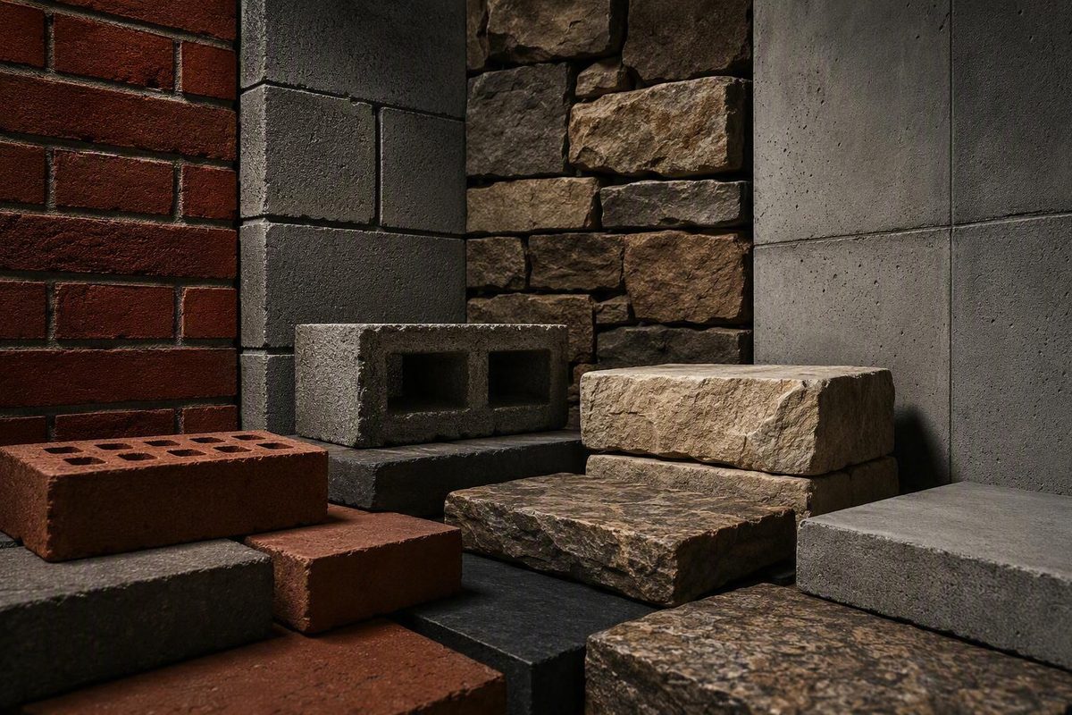
Masonry construction is not a single material or wall type. It is a family of assemblies built from individual units such as brick, natural stone, concrete masonry units, aerated concrete, and glass block. Depending on the system, mortar, grout, reinforcement, anchors, ties, insulation, flashing, and drainage components may be as important as the visible units.
That distinction changes how masonry should be selected and evaluated. A brick’s appearance or a block’s test value does not establish how the finished wall will carry loads, resist fire, control sound, conserve energy, or manage rain. Those outcomes belong to the complete assembly—including its supports, connections, workmanship, exposure, and maintenance.
What masonry construction includes
Masonry is construction made from individual units—commonly brick, natural stone, or concrete masonry units—typically laid in courses and bonded with mortar. It can form structural walls, facades, interior partitions, foundations, retaining walls, chimneys, piers, and landscape features. These are representative uses; not every masonry material or system is appropriate for every application.
The main components have distinct jobs:
-
Masonry units establish the wall’s geometry, surface, mass, and basic material character.
-
Reinforcement may be placed vertically or horizontally at designed locations to improve structural and lateral-load resistance.
- Anchors and ties connect masonry to backup walls, structural framing, or other construction.
- Insulation may be installed in a cavity, in suitable hollow units, outside a backup wall, or elsewhere within the designed assembly.
- Flashing, weeps, cavities, and drainage materials manage water that passes through or around the exterior layer.
Not every masonry wall contains every component. An unreinforced interior partition differs fundamentally from a reinforced load-bearing concrete masonry wall. A brick veneer may use mortar, ties, a cavity, insulation, flashing, and weeps without carrying the building’s principal gravity loads. A traditional solid stone wall may have neither a framed backup nor hollow cells, while a reinforced CMU wall can depend heavily on concealed steel and grout.
This leads to an essential distinction: unit properties are not assembly properties. The compressive strength of a brick or block alone does not determine the capacity of a wall. Nor does the material name establish a fire-resistance rating, thermal resistance, acoustic rating, or moisture performance. Wall thickness, mortar, grout, reinforcement, supports, openings, insulation, finishes, connections, and workmanship all affect the result. Industry guidance accordingly distinguishes among load-bearing, reinforced, veneer, and cavity systems rather than treating all masonry as equivalent (Autodesk’s masonry construction guide).
Structural design, foundations, retained-soil loads, reinforcement, anchorage, wind and seismic resistance, permits, and code compliance are project- and jurisdiction-specific. This article is an introductory coordination guide, not a structural design, enclosure specification, inspection standard, or substitute for approval by the governing authority.
The principal masonry materials and where they fit
The first material decision is not simply “brick or block.” It is a choice among units with different geometry, appearance, installation needs, exposure limits, and potential roles in the assembly.
Fired-clay brick is a modular unit available in many colors, textures, sizes, and finishes. Bond patterns can make the joints visually quiet or turn them into a defining architectural feature. Brick is frequently used for visible exterior walls and veneers, but appropriately designed brick masonry can also be structural.
Concrete masonry units, usually abbreviated as CMUs, are manufactured from cementitious materials and aggregates. Many common CMUs contain hollow cells. Depending on the design, selected cells may remain open, receive insulation, or contain reinforcement and grout. Manufacturers also offer shapes intended to resolve corners, lintels, horizontal reinforcement, and other conditions. The existence of hollow cells does not mean every cell should be filled.
Natural stone varies more than factory-made masonry. It can be structural in a suitable design, but contemporary construction also commonly uses stone as a facing anchored to separate backup construction. Rubble masonry uses irregular or roughly shaped pieces, while ashlar describes masonry made from more finely cut and regularly coursed stone. Variations in thickness, bedding orientation, shape, and surface make samples and installation planning especially useful.
Autoclaved aerated concrete, or AAC, contains distributed air pores and is cured in an autoclave. It is lighter than conventional dense masonry and is commonly described as more insulating than traditional masonry. Actual performance still depends on product density, thickness, joints, finishes, moisture conditions, and the complete wall configuration (Autodesk’s overview of masonry materials).
Glass block provides a translucent enclosure rather than a conventional opaque wall surface.
| Material | Typical role | Unit characteristics | Appearance | Installation implications | Reinforcement potential | Questions to verify |
|---|---|---|---|---|---|---|
| Fired-clay brick | Veneer, visible wall, landscape work, or designed structural masonry | Small modular units in varied sizes and exposure classifications | Broad range of colors, textures, bonds, and joint profiles | High unit count; coursing and opening dimensions strongly affect cuts and labor | Depends on the wall system and compatible details | Selected size, exposure suitability, absorption, bond, support, movement, and local availability |
| CMU | Structural walls, foundations, partitions, backup walls, and enclosures | Larger concrete-based units, often with hollow cells | Plain, split-face, ground-face, glazed, painted, coated, or concealed | Fewer units than small-format brick, but handling, reinforcement, grout, and finishes affect production | Hollow cells and compatible units can accommodate designed reinforcement and grout | Unit type, dimensions, density, finish, grout pattern, reinforcement, insulation, and exposure |
| Natural stone | Veneer, landscape work, monumental work, or designed structural construction | Variable natural pieces or accurately cut units | Irregular rubble through finely coursed ashlar | Sorting, fitting, supporting, and anchoring heavy units may require specialized labor | System-specific; veneer anchorage differs from reinforced unit masonry | Stone type, bedding, thickness, support, anchors, exposure, movement, and replacement supply |
| AAC | Unit-built exterior or interior walls in compatible systems | Lightweight, air-pored, autoclaved units | Usually uniform and commonly finished | Product-specific cutting, fastening, mortar, coating, and moisture details may apply | Product- and system-specific | Local supply, approved system, structural role, fasteners, finishes, moisture exposure, and code acceptance |
| Glass block | Translucent partitions, screens, entrances, and facade elements | Translucent units in product-specific configurations | Diffuses light while limiting direct visibility | Requires coordinated perimeter support, joints, and movement provisions | Limited and system-specific; generally not a primary structural wall | Approved use, panel configuration, supports, fire or safety requirements, movement, and exterior exposure |
This comparison is qualitative. It does not establish a universal strength, cost, insulation, or service-life ranking. Product availability, exact dimensions, structural role, exposure classification, workmanship, and local requirements can change the appropriate choice. Confirm the selected product rather than designing around a generic category.
Masonry wall systems: structure, veneer, cavities, and partitions
A material describes what the units are made from. A wall system describes what the completed assembly does.
Load-bearing masonry supports imposed building loads in addition to its own weight. It may support floors, roofs, beams, or other walls. Dimensions, slenderness, openings, lintels, bearing conditions, foundations, reinforcement, and connections must be resolved through the project design.
Reinforced masonry incorporates vertical or horizontal steel at designed locations, commonly coordinated with grout and compatible unit configurations. Reinforcement can increase capacity and resistance to wind, seismic, soil, or other lateral forces, but only as part of a designed and properly executed assembly.
Non-load-bearing masonry does not support the building’s primary gravity-load system. Typical examples include partitions and some enclosure walls.
Masonry veneer is a relatively thin facing anchored to separate backup construction. The building’s structural system carries the principal building loads. The veneer, backup, anchors, and supports perform the specific gravity- and lateral-support functions assigned by the design. The veneer also requires details for movement and drainage.
A cavity wall places a space between exterior masonry and a backup wall. Ties or anchors cross that space to provide the required connection. Insulation may also be located there if the wall design preserves its drainage function. The cavity is not evidence that the exterior masonry is impermeable; it is part of a strategy for collecting and draining water that passes the outer layer.
Flashing intercepts water at critical transitions and directs it toward the exterior. Weeps or other outlets let that water leave the wall. Ties provide the designed connection between veneer and backup, while the backup forms part of the structural, air-, water-, and thermal-control strategy.
Conceptual masonry veneer section—not a construction detail
EXTERIOR                                                   INTERIOR
   ↓                                                           ↓

  rain
   ↓
┌───────────────┐      clear drainage      ┌────────────┐  ┌──────────────┐
│ Exterior      │      space or cavity     │ Insulation │  │ Backup wall  │
│ masonry units │◄────────────────────────►│ where      │  │ and interior │
│ and mortar    │                           │ applicable │  │ construction │
│ joints        │──────── tie / anchor ─────────────────────►│
└───────────────┘                           └────────────┘  └──────────────┘
        │                                         ▲
        │ water drains downward                   │ flashing turns up
        ▼                                         │ at backup
     ┌────────────────────────────────────────────┘
     │ flashing directs collected water outward
     └───────────────► ○   ○   ○  weeps to exterior
This diagram shows relationships only. It does not establish materials, dimensions, tie spacing, flashing geometry, insulation thickness, structural support, or code compliance. Those details must come from the project documents and compatible product information.
| Project condition | Suitable starting point | Main coordination questions |
|---|---|---|
| Structural exterior wall | Designed reinforced masonry, possibly with a separate exterior finish or veneer | Loads, reinforcement, grout, openings, foundations, insulation, drainage, and connections |
| Architectural facade | Masonry veneer over suitable backup construction | Veneer support, anchors, cavity, flashing, weeps, insulation continuity, movement, and transitions |
| Interior partition | Non-load-bearing CMU, brick, glass block, or another compatible partition system | Floor support, top connection, lateral stability, services, acoustics, fire requirements, and movement |
| Foundation | Designed CMU or cast-in-place concrete system | Soil, groundwater, frost, loads, reinforcement, waterproofing, drainage, and backfill |
| Retaining wall | Engineered reinforced masonry or concrete system | Soil pressure, surcharge, stability, bearing, drainage, reinforcement, and adjacent conditions |
| Landscape wall | Low, non-retaining masonry or an appropriate landscape-wall system | Stability, soil and frost conditions, drainage, exposure, coping, utilities, boundaries, and local rules |
These are starting points, not specifications. Foundation and retaining-wall selection depends on site conditions, loads, drainage, and engineered stability rather than generic wall-building guidance.
Benefits and limitations at the complete-wall level
Durability, fire resistance, thermal mass, sound control, relatively low maintenance, and architectural character are frequently cited benefits of masonry. Each can be meaningful, but none is automatic.
A durable unit can still be part of a poorly performing wall if its support moves, the materials are incompatible, water is trapped, connections are omitted, or the wall top is left unprotected. Conversely, ordinary units can form an effective assembly when support, exposure, joints, drainage, and maintenance are properly coordinated.
Thermal mass is not the same as insulation and does not replace code-compliant insulation, air control, or treatment of thermal bridges.
Fire resistance belongs to a complete tested, approved, or appropriately calculated assembly—not simply to a material name or nominal wall thickness. Unit type, wall configuration, grout, finishes, joints, penetrations, and connections may all affect the result. Published brick-and-CMU comparisons likewise caution that stated fire ratings apply to specific assemblies rather than every wall of a given thickness (TheSiteMath’s U.S.-scoped comparison).
The same whole-assembly principle applies to sound control.
Masonry also presents practical constraints:
- Units and completed walls are heavy, affecting handling, support, and foundations.
- Unit-by-unit construction can be labor-intensive.
- Finished quality depends on layout, mortar control, alignment, tooling, and protection.
- Modular dimensions constrain opening locations, pier widths, and transitions.
-
Reinforcement, grout, anchors, flashing, and insulation create concealed coordination work.
-
Scaffolding, staging, lifting, cutting, and material storage can become major cost and schedule factors.
- Future alterations may require cutting, temporary support, new lintels, or restoration of structural, fire-, and moisture-control components.
Cracks can also provide paths for moisture.
The practical question is therefore not whether masonry is categorically better than another material. It is whether a particular assembly fits the wall’s structural role, exposure, appearance, construction sequence, maintenance expectations, and required performance.
Moisture, insulation, and movement: the details that govern performance
Exterior masonry should be treated as one layer in a managed water-control assembly, not assumed to be completely impermeable.
In a properly conceived veneer or cavity assembly, the intended path is straightforward:
- Some water passes through or around the exterior masonry.
- It reaches the cavity or drainage space behind the outer layer.
- Gravity carries it downward.
- Flashing intercepts it above a base, opening, support, or other critical transition.
- Weeps or other outlets allow it to leave toward the exterior.
Each component has a conceptual function:
- The drainage space separates the exterior masonry from more moisture-sensitive construction and provides a downward path.
- Flashing collects and redirects water.
- Weeps or drainage outlets let collected water exit.
- Below-grade waterproofing protects construction exposed to soil moisture or groundwater.
- Coping or other wall-top protection sheds water away from exposed tops.
The strategy can be undermined by obstructed drainage spaces, discontinuous flashing, blocked or missing outlets, or poorly protected wall tops. The same is true where water-control layers do not connect across openings, penetrations, and material transitions. These are design and coordination concerns; dimensions and product choices must come from project-specific details.
Movement is unavoidable. The project design must therefore coordinate the required joints, flexible interfaces, anchors, and perimeter connections. These provisions are not interchangeable generic gaps, and their placement should not be improvised in the field.
Foundation settlement is one recognized source of masonry cracking and associated moisture infiltration (NY Engineers’ masonry overview). As a conservative project boundary, obtain qualified assessment when cracks are changing, masonry is displaced or leaning, leakage persists, or the affected work is structural, below grade, or retaining soil.
Dimensions, coursing, mortar, and construction coordination
Masonry dimensions appear simple until actual units, mortar joints, openings, corners, and drawings must align.
An actual dimension is the manufactured size of the unit. A nominal or coordinated dimension commonly represents the space occupied by the unit plus its intended mortar joint. Terminology and standard modules vary by product and region, so specifications and product data should make clear which dimension is being used.
As U.S.-oriented examples, a commonly listed modular brick measures 3⅝ inches wide, 2¼ inches high, and 7⅝ inches long, while a frequently referenced standard CMU is 8 by 8 by 16 inches nominal (U.S.-scoped brick and CMU dimensional comparison). These are examples, not universal standards. Verify the selected manufacturer, unit profile, tolerances, joint assumptions, and regional conventions before dimensioning the work.
Coordinated unit-and-joint modules affect:
- overall wall lengths;
- opening widths and heights;
- sill, head, lintel, and bearing elevations;
- pier and return dimensions;
- corners and intersections;
- bond patterns;
- locations of cut units;
- quantity takeoffs;
- waste and breakage;
- labor and sequencing.
A small mismatch repeated across many courses can become a conspicuous field problem. Early coordination among plans, elevations, sections, structural details, opening schedules, and unit selections can reduce awkward cuts and unresolved interfaces.
Brick bonds organize how units and vertical joints relate from course to course. Common names include running or stretcher bond, header bond, English bond, Flemish bond, and stack bond. A bond’s name alone does not establish structural suitability.
Mortar beds and bonds units, fills joints, accommodates unit variation, and creates the finished joint profile. The highest-strength mortar designation is not automatically the right choice. Mortar should follow the project specification and compatible product requirements for the selected units, exposure, appearance, and structural role. A generic online ratio is not a substitute for those requirements.
Common layout and alignment controls include:
- dry layouts at corners, returns, and openings;
- string lines for course alignment;
- levels and plumb checks;
- gauging rods or marked references for course heights;
- measurements from stable control points;
- repeated checks during installation rather than correction only at the end.
An illustrated wall-building guide demonstrates the use of dry layouts, guide strings, levels, and repeated placement checks, but its footing and mortar examples remain project-specific rather than universal instructions (wikiHow’s illustrated brick-wall guide).
For a focused discussion of how one unit size can coordinate courses and openings, see Architecture News’s feature on modular brick dimensions and coursing. It is a coordination aid, not independent verification of engineering, code, cost, or performance requirements.
How to choose among brick, CMU, stone, poured concrete, and hybrid walls
Material selection should begin with the wall’s job. Appearance matters, but it comes after determining what the wall must support, separate, resist, and protect.
| Criterion | Brick masonry | CMU | Natural stone | Poured concrete | Hybrid masonry wall |
|---|---|---|---|---|---|
| Structural role | Veneer or designed structural masonry | Often structural or used as backup; may also be non-load-bearing | Structural in suitable designs, but often used as veneer | Continuous structural wall formed in place | Structural and exterior-finish roles assigned to different layers |
| Moisture exposure | Requires exposure-suitable units, joints, and deliberate drainage | Requires a suitable coating, waterproofing, drainage, or cavity strategy by location | Stone, joints, anchors, support, and backup must suit exposure | Fewer unit joints, but cracks, penetrations, joints, and waterproofing still matter | Cavity, flashing, and weeps manage water behind the facing |
| Below-grade use | Application-specific and less common as exposed finished brick | Common candidate where designed and protected for the conditions | Limited and highly project-specific | Common candidate for foundations and retaining conditions | Usually the foundation or backup—not the veneer cavity—continues below grade |
| Appearance | Often the finished visible surface | May be exposed, textured, painted, coated, or concealed | Highly variable natural character | Usually formed, coated, clad, or otherwise finished | Combines a structural backup with a distinct exterior finish |
| Unit or placement scale | Small units and many joints | Larger units with fewer pieces | Variable pieces or cut units | Placed continuously within forms | Multiple coordinated layers and trades |
| Installation sequence | Course-by-course and strongly tied to module | Course-by-course, with reinforcement and grout stages where required | Sorting, cutting, setting, supporting, and anchoring may be labor-intensive | Form, reinforce, place, consolidate, cure, and strip | Backup, controls, insulation, ties, veneer, flashing, and weeps must align |
| Schedule | Sensitive to unit count, details, access, and weather | Can suit phased work, although grout and reinforcement affect production | Often sample-dependent and labor-intensive | Can suit large continuous placements but requires formwork and curing | More interfaces and sequencing, with opportunities for trade overlap |
| Future alterations | New openings require support and restoration of surrounding work | May accommodate phased construction and later openings, subject to reinforcement and loads | Alteration can be difficult where units are irregular or heavy | Cutting a continuous reinforced wall can be disruptive | Both backup and veneer must be evaluated |
| Insulation strategy | Commonly placed in a cavity or at the backup | May use continuous insulation, suitable cell insulation, or another designed approach | Usually governed by the backup-wall assembly | Usually requires a separate insulation strategy | Continuous insulation can be coordinated behind veneer |
| Labor availability | Requires bricklaying and finish-joint skills | Requires unit-laying plus reinforcement and grout coordination | Skilled fitting, support, and anchoring may be critical | Requires forming and concrete-placement resources | Requires coordination among masonry, structure, enclosure, and insulation work |
| Budget | Driven by unit, labor, support, details, access, and region | Driven by block, steel, grout, finishes, handling, and access | Driven by stone selection, transport, fabrication, support, and labor | Driven by forms, reinforcement, placement, access, and scale | Must include both backup and veneer systems, not only the face material |
Brick is frequently chosen for visible finished surfaces and veneers because color, texture, scale, and bond can form the final architecture. It can also be used structurally where the wall is designed for that role.
CMU is commonly considered for structural walls, foundations, partitions, fire separations, backup walls, and phased construction. Reinforcement, grout, insulation, coatings, and finishes can substantially change its role and performance.
Stone is often selected for appearance and durability in a suitable exposure. Its weight, variable geometry, support, anchorage, and labor requirements should be recognized early. Many contemporary stone facades are veneers rather than full-depth structural stone walls.
Poured concrete and CMU should be compared as complete systems rather than stereotypes. Poured concrete creates continuous sections and is often considered for foundations, retaining work, and large uninterrupted walls. CMU may suit phased work and can make some later modifications more manageable. Neither is always stronger, faster, drier, or cheaper; wall size, loads, formwork, labor, reinforcement, waterproofing, access, and schedule determine the outcome (Seufert Construction’s qualitative poured-concrete and CMU comparison).
A common hybrid exterior uses:
- a structural CMU backup;
- exterior insulation;
- a drainage cavity;
- brick veneer;
- ties connecting the veneer to the backup;
- flashing at bases and interruptions; and
- weeps or outlets discharging toward the exterior.
This arrangement assigns different functions to different layers. The CMU provides the designed backup, insulation controls heat flow, brick establishes the exterior finish, ties stabilize the veneer as designed, and the cavity-flashing-weep system manages infiltrating water. Commercial brick-and-block comparisons identify this division of structural and appearance roles as a common hybrid approach (Magnolia Brick’s system comparison).
Do not rank these walls using unit compressive strength alone. Complete-wall capacity depends on geometry, mortar, grout, reinforcement, openings, supports, connections, workmanship, loads, and the design method.
A useful selection sequence is:
- Define the wall’s job.
- Identify gravity, lateral, soil, water, impact, and other relevant loads or exposures.
- Establish the required structural, fire, thermal, acoustic, and moisture performance.
- Compare constructability, appearance, access, and sequence.
- Estimate the complete system rather than the visible unit alone.
- Obtain the required design, product approvals, permits, and inspections.
Planning, estimating, quality checks, and the DIY boundary
Masonry problems often begin before the first unit is laid. A preconstruction review should resolve the following:
- [ ] What is the wall’s purpose?
- [ ] Is it load-bearing, retaining, veneered, freestanding, or non-load-bearing?
- [ ] Which exact units, colors, textures, shapes, and exposure classifications are selected?
- [ ] Are actual dimensions, nominal modules, and joint assumptions confirmed?
- [ ] What bond or coursing module governs the elevations?
- [ ] Do openings, sills, heads, lintels, bearings, corners, and piers fit the module?
- [ ] What supports the wall, and is that support ready?
- [ ] What is the backup construction?
- [ ] Where does the design require reinforcement or grout?
- [ ] How are ties, anchors, and connections coordinated?
- [ ] Where are insulation, air-control, water-control, and drainage layers?
- [ ] How will flashing remain continuous and drainage outlets remain open?
- [ ] How are wall tops, parapets, sills, and penetrations protected?
- [ ] Where does the design require movement accommodation?
- [ ] Is access available for deliveries, scaffolding, lifting, grouting, and inspection?
- [ ] What weather protection is required during storage and construction?
- [ ] Which permits, inspections, submittals, tests, or local approvals apply?
This checklist identifies coordination subjects. It is not a complete design or inspection protocol.
A transparent estimating framework
Avoid relying on a universal cost per square foot. Build the estimate from the assembly:
- field units and specialty shapes;
- mortar materials;
- grout;
- vertical and horizontal reinforcement;
- anchors, ties, fasteners, and accessories;
- lintels, shelf supports, and bearing components;
- flashing, end conditions, weeps, drainage materials, and sealants;
- insulation and air- or water-control layers;
- coatings, plaster, stucco, paint, or other finishes;
- coping, caps, and wall-top protection;
- footing concrete, forms, reinforcement, excavation, and drainage;
- scaffolding, lifts, mixers, pumps, cutting equipment, and protection;
- delivery, unloading, storage, and material handling;
- labor for layout, laying, grouting, tooling, cleaning, and inspection support;
- cuts, corners, bond adjustments, breakage, waste, and mockups;
- weather delays, phasing, restricted access, and remobilization.
Larger units reduce the number of pieces required to cover a wall, but that does not automatically make the completed system faster or cheaper. Unit weight, crew productivity, reinforcement, grout, openings, finishes, access, weather, cleaning, and sequencing can offset the apparent advantage.
Introductory construction-stage checks
The project team’s checks should be defined by the drawings, specifications, applicable approvals, and required inspection program. At an introductory coordination level, typical subjects include:
- readiness of the footing, shelf, slab edge, or other support;
- identity, condition, storage, and compatibility of units;
- mortar conformity with project requirements;
- wall location and required clearances;
- course height, bond, alignment, plumb, and level;
- joint filling, consistency, tooling, and appearance;
- designed reinforcement before it becomes concealed;
- grout placement where required;
- tie and anchor installation;
- flashing continuity and termination;
- clear cavities and drainage paths;
- continuity at penetrations, openings, corners, and transitions;
- temporary bracing and weather protection where required;
- protection of completed work from damage and contamination.
These observations do not replace special inspection, testing, engineering review, manufacturer instructions, or code-required verification.
Where DIY masonry should stop
A small, low, non-retaining, non-load-bearing landscape wall may be within the scope of an experienced DIY builder. Retaining walls, load-bearing walls, tall freestanding walls, foundations, below-grade construction, significant excavation, and walls resisting wind or seismic forces are in a different risk category. A UK-oriented commercial bricklaying guide similarly limits its basic instructions to simple non-load-bearing work and directs structural brick-wall projects to professionals (Brickhunter’s basic brick-wall guide).
For a genuinely simple landscape wall, the general sequence is:
- Define the wall’s purpose and confirm that it is not retaining soil or carrying building loads.
- Check property boundaries, buried services, permissions, and local requirements.
- Lay out the wall and coordinate its unit module.
- Prepare support suitable for the soil, frost conditions, drainage, wall geometry, and selected system.
- Dry-lay critical courses, corners, and returns.
- Place mortar and units in manageable stages.
- Stagger joints according to the selected bond.
- Check line, level, plumb, and course gauge repeatedly.
- Finish joints at the appropriate stage.
- Protect the work while the mortar develops the required performance.
- Install coping or another suitable wall-top treatment where the system requires it.
This sequence is not a footing design or structural specification. Do not adopt generic trench dimensions, mortar ratios, joint dimensions, or curing periods as universal rules. Published garden-wall examples vary because soil, frost depth, drainage, exposure, wall height, unit type, product instructions, and regional practice vary. UK retail guidance also treats retaining walls as requiring additional foundation and drainage consideration rather than ordinary garden-wall instructions (Beatsons’ garden-wall overview).
Consult a qualified mason, structural engineer, architect, geotechnical professional, or governing authority when the work involves imposed loads, retained soil, significant excavation, foundation design, reinforcement, permits, fire-rated construction, or tested assemblies.
Is masonry construction always load-bearing?
No. Masonry can be load-bearing, reinforced, non-load-bearing, or used as veneer. A masonry partition may carry only its own weight and applicable lateral loads, while veneer functions as a facing connected to separate backup construction.
The drawings and specifications should state the wall’s role. It should never be inferred solely from the visible material.
What is the difference between masonry veneer and a solid masonry wall?
Masonry veneer is a relatively thin facing supported for its own weight and anchored to separate backup construction. It is not normally the building’s principal gravity-load system.
Veneer commonly includes a cavity, anchors, flashing, and weeps; solid masonry may use a different moisture- and thermal-control strategy. The systems should not be detailed as interchangeable.
Is brick better than concrete block?
Not categorically. Brick is frequently selected for finished appearance, scale, texture, and veneer work. CMU is commonly selected for structural walls, backup walls, foundations, partitions, and phased construction. Brick can be structural, and CMU can be architectural.
The better option depends on loads, exposure, insulation, finishes, reinforcement, labor, schedule, local availability, and total assembly cost. Comparisons based only on unit strength, purchase price, or insulation overlook the rest of the wall.
Are masonry walls waterproof and naturally well insulated?
Not necessarily. Exterior masonry should be detailed as part of a water-management system using compatible drainage spaces, flashing, outlets, sealed transitions, wall-top protection, and below-grade waterproofing where applicable. The outer masonry may shed much of the rain, but the assembly should account for possible water penetration.
Masonry also provides thermal mass, not automatic insulation. Energy performance depends on the full wall configuration, including insulation continuity, cavities, grout, moisture, finishes, and thermal bridges.
Can masonry construction be a DIY project?
A small, non-retaining, non-load-bearing landscape wall may be appropriate for an experienced DIY builder who understands layout, mortar handling, support preparation, weather protection, and local requirements.
Retaining, load-bearing, tall, below-grade, foundation, wind-resisting, or seismic masonry should not be treated as an ordinary garden-wall project. Those conditions can involve structural design, soil behavior, drainage, reinforcement, permits, inspections, and construction hazards that warrant qualified professional involvement.
Successful masonry construction comes from choosing a complete wall assembly—not merely a brick, block, or stone. Define the wall’s structural and environmental job, coordinate unit dimensions with openings and details, provide deliberate paths for loads, movement, heat, and water, and estimate every component needed to make those paths work. Then verify the project-specific design, products, approvals, and construction requirements with qualified professionals and the governing jurisdiction.