
How Reinforced Stem-and-Footing Walls Hold Back Soil
The wall and footing can satisfy local sliding, overturning, and bearing checks while the wider slope remains unstable. All six checks interact.
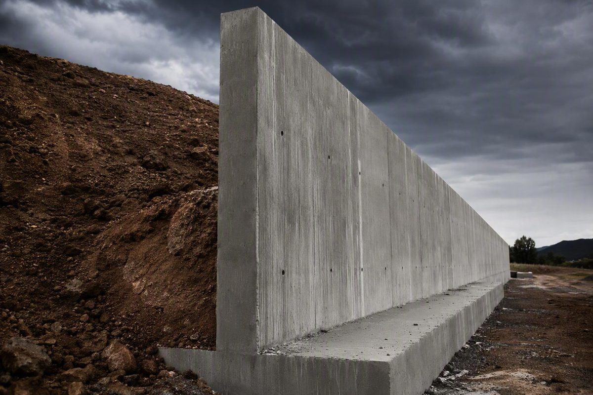
How reinforced stem-and-footing walls hold back soil
A cantilever retaining wall looks simple: a vertical wall rises from a horizontal footing and separates two ground elevations. Its performance, however, depends on an interdependent system. The reinforced stem, heel, toe, foundation soil, backfill, drainage, groundwater assumptions, and construction sequence must work together.
That distinction matters. A strong stem does not prevent the whole wall from sliding. A wide footing does not stabilize a larger unstable slope. Reinforcement selected for dry backfill may also be inadequate if water accumulates behind the wall.
This article provides a jurisdiction-neutral technical overview for architects, contractors, estimators, students, owners, and early-career professionals. It explains design logic and system selection, but it does not provide project dimensions, reinforcement schedules, load combinations, or construction-ready calculations.
What a cantilever retaining wall is—and how the load path works
A cantilever retaining wall generally consists of a reinforced concrete or reinforced masonry stem structurally connected to a reinforced base slab or footing. The stem retains the soil. The footing transfers loads into the supporting ground and provides the geometry needed to resist sliding and overturning.
The stem acts conceptually as a vertical cantilever fixed at its base. Lateral pressure bends the stem, which transfers bending and shear into the footing. The footing has two principal projections:
- The heel extends behind the stem, beneath the retained backfill.
- The toe extends from the stem toward the exposed side.
- The base slab includes the heel, the portion beneath the stem, and the toe.
- An optional shear key may project below the footing.
These terms are used consistently in common descriptions of concrete cantilever walls, which distinguish the relatively thin reinforced stem from the heel beneath the backfill and the toe on the opposite side (Concrete Network’s comparison of retaining-wall types).
Conceptual cross-section
                  RETAINED SIDE
        surcharge, traffic, slope, or other loads
                             ↓
        retained backfill  /////////
                          /////////│
                         ///////// │  ← reinforced stem
                        /////////  │
 drainage zone →       ▒▒▒▒▒▒▒▒▒  │      EXPOSED SIDE
 drain/outlet →        o───────────│
───────────────────────┬───────────┴──────── exposed grade
                       │
        HEEL           │ STEM BASE       TOE
<──────────────────────┼───────────><────────────>
══════════════════════════════════════════════════  ← base slab/footing
                       │
                       │ optional shear key
                       ▼
~~~~~~~~~~~~~~~~~~~~~~~~~~~~~~~~~~~~~~~~~~~~~~~~~~  ← foundation soil
The drawing is conceptual. Project geometry, drainage provisions, materials, grades, and footing configuration must be established for the actual site.
How the forces reach the ground
The basic load path is:
- Soil, water, and surcharge create lateral pressure against the retained side.
- The stem resists that pressure through bending and shear.
- The stem transfers its reactions into the footing.
- The footing distributes compression into the foundation soil.
- Footing–soil interaction resists horizontal movement.
- Wall weight and soil over the heel contribute stabilizing force and moment.
Soil over the heel is part of the external-stability model, not merely excavation backfill. Its weight can help resist overturning. If that soil is removed or replaced with materially different fill, the assumptions used in design may no longer describe the completed wall.
The heel and toe also bend. Under common loading, the heel carries downward loads from retained soil and surcharge while receiving upward foundation reaction. The toe is loaded primarily by upward foundation reaction. Their typical reinforcement patterns therefore differ, although actual bar locations, sizes, cover, development, and splices require structural design.
A shear key is optional rather than a defining feature of every cantilever wall. It projects below the footing and may be used to engage soil at a deeper level when additional sliding resistance is needed. Its value depends on the soil and on whether the assumed resistance can be mobilized and maintained. Changing the footing, improving foundation conditions, reducing loads, or selecting another retaining system may be more appropriate.
Forces on the wall: soil is only the starting point
Under a simplified condition with level, uniform backfill and no surcharge, lateral soil pressure is commonly represented as increasing with depth. Pressure is smallest near the top and greatest near the base, producing a triangular conceptual diagram.
SOIL PRESSURE                  UNIFORM SURCHARGE
│ │■■
│ │■■
depth │ depth │■■
│ │■■
│____ │■■
      increasing                     approximately
      pressure                       uniform increment
Water below a groundwater level also produces pressure that increases with depth below the water surface:
WATER PRESSURE

groundwater level ─────────
│\
depth │ \
│ \
│___\
                     increasing
                 hydrostatic pressure
These diagrams show general shapes, not reusable design values. Actual distributions depend on the soil model, wall movement, groundwater, surface geometry, surcharge position, and analytical method.
Soil properties and surface geometry
Retained height is a major variable because both lateral pressure and its lever arm generally increase as the wall becomes taller. Height alone is insufficient, however. The design also needs to address:
- Soil unit weight
- Frictional strength
- Whether any cohesion is appropriate to use
- Layered or variable soils
- Backfill characteristics
- Level or sloping ground
- The slope below the wall
A slope rising behind the stem does not represent level, unloaded backfill. A descending slope in front may also change the geometry available to support the wall and can raise questions about the stability of the larger slope.
Surcharges and nearby loads
A surcharge is a load applied at or near the ground surface behind the wall. Examples include:
- Parking and roadway loads
- Stored materials
- Construction equipment
- Building slabs or foundations
- Pedestrian areas
- Landscape features
- Future development
A strip load, such as a loaded lane or limited-width foundation, has a different influence. Concentrated loads can also act near the wall or at the top of the stem. Retained soil, uniform and strip surcharges, concentrated top loads, groundwater, wind, and seismic effects are distinct design inputs (ASDIP’s retaining-wall design overview).
Three common scenarios illustrate why generic diagrams are limited:
- Parking lot: Vehicles create surcharge, while a barrier or guard may introduce a separate load near the stem.
- Nearby building: Foundation loading may influence the retained soil and may restrict wall movement.
- Sloping backfill: The retained geometry differs from level backfill and requires an appropriate earth-pressure model.
Temporary conditions also matter. Construction machinery or stored material placed behind the wall can create a surcharge different from the eventual final-use condition.
Groundwater and drainage assumptions
Groundwater can add hydrostatic pressure and alter the soil conditions used to assess sliding, bearing, and construction feasibility. A dry-soil model cannot simply be retained if credible conditions would allow water to accumulate behind the stem.
The design must define the groundwater condition being considered, how drainage is expected to control water, and whether another condition must be evaluated if drainage cannot provide the assumed relief. Drainage is therefore part of the loading model, not merely a landscaping detail.
Wind and seismic effects
Where the stem projects above the retained soil, its exposed portion or an attached fence, screen, guard, or sign may introduce wind loading.
Seismic effects must be addressed where required by the governing jurisdiction. The appropriate analysis depends on the site, wall, soil, restraint, seismic parameters, and applicable requirements. A generic percentage taken from an unrelated example is not a substitute for project-specific evaluation.
Active, at-rest, and passive pressure depend on movement
Earth pressure depends not only on the soil but also on whether the wall can move and in which direction.
Active pressure
Active earth pressure is associated with a wall moving sufficiently away from the retained soil. This movement allows the soil to expand laterally and approach an active condition.
A freestanding cantilever wall may be able to rotate or translate enough for an active-pressure model to be considered. That conclusion cannot be drawn from the wall’s name alone. Connections to slabs, return walls, braces, corners, or other structures may restrict movement.
At-rest pressure
At-rest earth pressure represents a condition in which lateral soil strain is restrained and the wall does not move enough to mobilize the active state.
If floors or other structural elements brace the wall, it may be unable to move away from the soil sufficiently.
Can the wall move away from the retained soil sufficiently?
        │
        ├── Yes, and movement is compatible with the structure
        │      └── Active pressure may be an appropriate framework
        │
        └── No, uncertain, or structurally restrained
               └── Evaluate at-rest pressure or another suitable model
This is a conceptual decision path, not a substitute for geotechnical judgment.
Passive pressure
Passive earth pressure is resistance developed when a wall, footing, or shear key pushes into soil. It may contribute to sliding resistance, but it generally requires more movement to mobilize than active pressure.
Its availability must also be considered. Soil credited in front of a toe or key must remain present and suitable for the design assumption. Where that availability is uncertain, passive resistance may be reduced or omitted.
Rankine and Coulomb frameworks
Rankine and Coulomb are established earth-pressure frameworks with different idealizations. At a high level, Rankine uses simplified wall and soil-interface assumptions, while Coulomb can account for wall–soil friction and additional geometric variables. Neither method eliminates the need to select suitable soil properties, groundwater conditions, surcharge cases, and wall-movement assumptions.
Measured behavior can differ from an idealized pressure diagram. A Texas Transportation Institute report published in May 1983 documented a field wall whose pressures and movements were monitored along with testing of foundation and backfill soils (the government-sponsored field report). It illustrates the influence of actual site conditions, but its historical procedure and project-specific results are not a current universal design standard.
The six checks behind an apparently simple wall
A cantilever retaining wall must be evaluated at multiple scales. Some checks concern movement of the complete wall, others concern the supporting ground, and others address the reinforced stem and footing.
| Failure mode | What could happen | Principal questions | Possible design responses |
|---|---|---|---|
| Sliding | The wall translates horizontally | Do driving loads exceed dependable footing–soil resistance? Is any passive resistance appropriate to credit? | Change geometry, improve foundation conditions, reduce loading, add an engineered key, or change systems |
| Overturning | The wall rotates toward the exposed side | How do overturning and stabilizing moments compare? Where does the foundation resultant act? | Revise footing geometry or wall elevation, reduce loads, or select another system |
| Bearing and settlement | Foundation soil is overstressed or deforms | Are contact pressures, eccentricity, and settlement acceptable? | Modify the footing, improve the ground, use deep support, or change systems |
| Global instability | A larger soil mass moves around or beneath the wall | Is the wall located within a stable retained mass or slope? | Regrade, improve drainage, reinforce the soil mass, use deep support, or relocate the wall |
| Structural flexure | Stem, heel, or toe cracks or yields in bending | Are member thickness, reinforcement, and load transfer adequate? | Revise member geometry or reinforcement |
| Structural shear | A member or connection fails in shear | Are critical sections and junctions adequate? | Increase depth, revise geometry or reinforcement, or reduce demand |
These stability and structural checks are commonly treated as separate but interdependent parts of cantilever-wall design.
Sliding
The sliding check compares driving horizontal loads with dependable resistance at or below the footing. That resistance may include footing–soil interaction established from the geotechnical design. Any passive contribution should reflect the movement needed to mobilize it and whether the relevant soil will remain available.
A shear key can engage deeper soil, but it is not a universal solution. Its performance still depends on the foundation profile and the design assumptions assigned to that soil.
Overturning
Overturning is assessed by comparing moments about a selected reference point, often near the toe. Lateral pressures create overturning moments. The weights of the wall, footing, and soil over the heel create stabilizing moments.
The concern is not limited to a wall tipping as a rigid block. Rotation changes the contact-pressure distribution beneath the footing. Increasing eccentricity can concentrate compression toward one side and change both foundation and structural demands.
Foundation bearing and settlement
Allowable bearing pressure is only one part of foundation evaluation. The design may also need to consider:
- Maximum and minimum contact pressure
- Eccentricity of the foundation resultant
- Total settlement
- Differential settlement
- Variation in supporting materials
- Groundwater conditions
- Effects on nearby structures or utilities
A bearing-pressure check alone does not establish that the foundation is adequate. Likewise, published safety factors and middle-third criteria are source-specific guidance. Their applicability depends on the governing requirements, design method, load combinations, agencies, and seismic condition.
Global instability
Global instability involves a larger soil mass moving behind, beneath, or in front of the wall. The wall and footing can satisfy local sliding, overturning, and bearing checks while the wider slope remains unstable.
This is a geotechnical problem requiring an appropriate ground model and stability analysis. Increasing the reinforcement in the stem does not address a potential failure surface that passes around the wall.
Structural flexure
Under common lateral loading, stem bending demand is greatest near the footing connection. Primary vertical stem reinforcement is therefore commonly located near the backfill face.
The heel and toe usually bend in different directions:
- The heel commonly has primary reinforcement near its top.
- The toe commonly has primary reinforcement near its bottom.
These are conceptual patterns documented in retaining-wall design guidance, not project detailing instructions. Geometry, load reversals, construction stages, top loads, and other conditions can change the required reinforcement.
Structural shear
Shear must be evaluated in the stem, footing projections, stem-to-footing junction, and any shear key. Reinforced masonry also depends on reliable load transfer through reinforced and grouted cores and the connection to the concrete footing.
The checks interact. Widening a heel may improve overturning resistance but require more excavation. Adding a key changes the sliding mechanism. Thickening the footing adds weight but also changes bearing and material demand. Design is iterative rather than a set of isolated pass-or-fail calculations.
Geotechnical information and drainage that must exist before design
A credible design begins with a credible ground model. An assumed soil type or a bearing value copied from another project is not enough.
Pre-design geotechnical checklist
The project’s investigation and recommendations should address, as applicable:
- Soil or rock profile beneath and behind the wall
- Soil unit weights
- Friction parameters and treatment of any cohesion
- Allowable bearing pressure under the selected design basis
- Total and differential settlement characteristics
- Groundwater level and credible variation
- Footing–soil sliding interaction
- Suitability and compaction requirements for backfill
- Frost conditions where relevant
- Global slope stability
- Need for foundation improvement or deep support
Cohesion requires particular care. Whether it can be relied on depends on the soil, condition, time frame, disturbance, and adopted geotechnical model.
Site geometry and constraints checklist
The design team also needs:
- Retained height and proposed grades
- Slopes above and below the wall
- Topographic and boundary information
- Adjacent structures and foundation elevations
- Existing utilities
- Available excavation and construction access
- Final traffic, storage, landscape, and barrier loads
- Construction equipment and stockpile locations
- Anticipated future development
- A feasible drainage outlet
A conventional heel may fit physically but conflict with a boundary, utility corridor, adjacent foundation, or excavation constraint. Land rights, approval requirements, and restrictions on adjacent work must be verified for the project and jurisdiction.
Groundwater is not established by one dry visit
A site that appears dry at one time may experience different groundwater or seepage conditions later. The design should use the conditions established by the project’s geotechnical assessment rather than assuming that water is absent because it was not visible during a single visit.
Drainage as a load-control system
Drainage is intended to prevent water from accumulating behind the stem. At a conceptual level, it may include:
- Free-draining material behind the wall
- Through-wall outlets where appropriate
- A continuous longitudinal collector drain where appropriate
- A dependable discharge point
- Surface grading coordinated with the wall
A pipe without a functioning discharge path does not provide dependable pressure relief. The drainage concept must connect the retained zone to an operable outlet. Concrete masonry guidance similarly treats drainage, suitable founding material, frost conditions, and controlled backfilling as integral parts of wall construction (CMHA guidance for concrete masonry cantilever walls).
Drainage versus waterproofing
Drainage and waterproofing perform different functions:
- Drainage controls water accumulation and the pressure it can create.
- Waterproofing or dampproofing limits moisture transmission through the wall.
Its need and form depend on the wall’s exposure and what lies on the protected side.
Weak or compressible ground, high groundwater, variable foundation conditions, unstable slopes, or severely restricted excavation may justify foundation improvement or a different retaining system.
When a cantilever wall fits—and when another system may fit better
Cantilever walls can provide a relatively compact finished face with less concrete mass than a monolithic gravity wall. The completed appearance can be misleading, however: a conventional heel may still require substantial excavation behind the stem.
Neutral system-selection table
| System | Principal resistance concept | Space and construction implications | Conditions that may favor it |
|---|---|---|---|
| Cantilever stem and footing | Reinforced stem and footing; wall and heel-soil weight contribute to stability | Compact finished face, but a conventional heel needs rear excavation | Moderate grade changes, defined geometry, suitable foundation, available excavation |
| Gravity wall | Mass resists lateral loading | Becomes bulky as height and load increase | Lower walls and sites where sufficient footprint is available |
| Counterfort wall | Webs connect the stem and base, reducing bending spans | More complex forming and reinforcement | Taller walls where structural efficiency offsets added complexity |
| Reinforced-soil or geogrid wall | Reinforced backfill mass supports the face | Requires a reinforcement zone behind the face | Fill sites with adequate right-of-way and suitable reinforced fill |
| Anchored wall | Anchors transfer load behind the retained face | Requires suitable drilling access, bond zones, and project rights | Restricted excavation or high loading where anchors are feasible |
| Soldier-pile, sheet-pile, or similar embedded wall | Embedded vertical elements resist retained-ground loads | Can reduce open excavation but requires specialized installation | Property-line work, deep cuts, or constrained sites |
| Soil-nail wall | Reinforcement is installed progressively into an exposed cut | Requires suitable ground and installation access | Top-down excavation or existing cuts where the method is appropriate |
No system is universally strongest, safest, cheapest, or most space-efficient. Selection depends on retained height, surcharge, soils, groundwater, seismic demand, footprint, access, neighboring structures, sequence, appearance, and total project cost.
Cantilever versus gravity
A gravity wall relies primarily on mass. A cantilever wall uses reinforcement and structural action, allowing it to perform the same broad retaining function with less concrete mass. The tradeoff is more engineering, reinforcement, construction control, and often more complex excavation.
Gravity systems may remain attractive for lower walls where adequate footprint is available. As height and loading increase, the required mass can become impractical.
Counterfort walls
Counterfort walls add regularly spaced reinforced webs connecting the back of the stem to the base. These webs reduce bending spans in the stem and footing. The structural benefit comes with added formwork, reinforcement congestion, and geometric complexity.
Published transition heights are only economic rules of thumb. They vary with labor, materials, loading, foundation conditions, and construction methods rather than defining a structural limit.
Reinforced-soil systems
Mechanically stabilized or geogrid-reinforced systems form a reinforced soil mass behind the face. They can be effective where adequate reinforcement length is available. Utilities, boundaries, existing foundations, and restricted excavation may make that space unavailable.
The property-line problem
A wall face may fit near a boundary while its heel or excavation does not. Before selecting the system, the project team must confirm the available physical space and the rights needed for permanent components, temporary excavation, anchors, and access.
Where a conventional heel is impractical, an anchored, soldier-pile, soil-nail, sheet-pile, specially configured footing, or other embedded system may be considered. Each has distinct ground, access, installation, and approval constraints.
Height ranges are not universal limits
Published guidance gives conflicting practical ranges. Concrete Network describes cantilever concrete walls as generally economical up to about 25 feet, while Tensar describes cantilever walls as suitable for retained heights up to about 5 metres; both are broad commercial rules of thumb rather than structural maxima (Tensar’s overview of retaining-wall types).
Other commercial guidance for residential and light-commercial work mentions cantilever walls up to approximately 25–30 feet, again subject to project conditions rather than as a universal limit (Calcs.com’s retaining-wall overview).
A feasible cantilever wall may still be inferior to another system once excavation, dewatering, reinforcement congestion, lifting, schedule, and risk are considered.
Cast-in-place concrete, reinforced masonry, and precast options
The cantilever principle can be built in several ways. The load path may be similar, but the site operations and constraints differ.
Cast-in-place reinforced concrete
Cast-in-place concrete offers substantial geometric flexibility. Stem thickness, footing geometry, alignment, and architectural finish can be adapted to the project.
A typical high-level sequence includes:
- Excavate and prepare the work area.
- Verify the foundation condition.
- Install footing reinforcement and embedded items.
- Place and cure footing concrete.
- Form and reinforce the stem.
- Place, consolidate, cure, and protect the stem concrete.
- Install the specified drainage and moisture-control work.
- Backfill in a controlled sequence after adequate strength is available.
The construction sequence described in commercial guidance likewise includes excavation, reinforced footing construction, formwork, reinforcement, concrete placement, curing, drainage, and layered backfilling. Actual temporary works and placement procedures must be established for the site.
Reinforced masonry
A reinforced masonry wall uses concrete masonry units for the stem. Vertical reinforcement is placed in selected cores, which are grouted to complete the structural section. Dowels connect the stem to a reinforced concrete footing, and horizontal reinforcement may also be required.
It also requires control of unit placement, reinforcement alignment, grout spaces, grout placement, strength development, and the timing of backfill.
Proprietary hollow-core systems may combine a concrete footing, vertical and horizontal reinforcement, and concrete-filled cores. Such arrangements exist, but reinforcement and capacity must be established in project-specific engineering documents rather than inferred from marketing descriptions (MagnumStone’s reinforced hollow-core system).
Precast L-shaped units
Precast L-walls integrate the stem and base into factory-made units. They can reduce site forming and curing work, but shift project effort toward:
- Transport and delivery planning
- Unit weights
- Lifting capacity and access
- Prepared bearing surfaces
- Bedding and leveling
- Installation tolerances
- Joint alignment
- Drainage continuity
- Temporary handling and placement planning
A manufacturer may permit different support preparations for particular products and ground conditions. That does not establish a general rule that precast retaining walls need no concrete foundation. The foundation or prepared base must suit the actual ground, loading, tolerances, drainage, and product engineering.
Construction-system comparison
| Constraint | Cast-in-place concrete | Reinforced masonry | Precast L-shaped units |
|---|---|---|---|
| Custom geometry | High flexibility | Governed by unit module and detailing | Limited by available or custom units |
| Site formwork | Usually substantial | Mainly footing forms | Usually limited |
| Site curing | Footing and stem | Footing and grout | Foundation or bedding work; units arrive cured |
| Lifting plant | Depends on forms and reinforcement | Usually conventional material handling | Often a governing requirement |
| Transport | Concrete delivered in batches | Units, grout, and steel delivered separately | Large unit size and weight can govern logistics |
| Site access | Needed for crews, forms, and concrete placement | Needed for masonry and grout operations | Must accommodate delivery and lifting radius |
| Joints | Designed construction and movement joints | Masonry joints and project-specific movement provisions | Repeated joints between units |
| Foundation preparation | Project-specific footing | Reinforced concrete footing | Project-specific foundation or prepared base |
| Installation tolerances | Controlled through formwork | Controlled through coursing and alignment | Critical to bearing, level, joint fit, and alignment |
| Schedule sensitivity | Forming, placement, and curing | Masonry production, grouting, and strength gain | Manufacturing, delivery, lifting, and base preparation |
Product dimensions, weights, capacities, and installation claims are manufacturer-specific. One manufacturer, for example, publishes an L-shaped unit range extending from 500 mm to 4,500 mm high, with listed weights varying by unit size; those figures describe that product range and still require project verification (CBS’s precast cantilever-wall information).
The system choice should follow design compatibility and site logistics—not unverified claims about universal installation speed, strength, service life, or foundation requirements.
From investigation to backfill: the project and construction sequence
A retaining wall should progress through coordinated investigation, design, approval, construction, and verification rather than moving directly from a sketch to excavation.
1. Survey the site
Document existing and proposed grades, wall alignment, boundaries, nearby structures, drainage features, and access constraints. Confirm that the permanent wall and the space needed to build it fit the project conditions.
2. Review utilities
Identify relevant overhead and underground services and determine how they affect the wall, excavation, drainage, and future access.
3. Investigate the ground
Develop a geotechnical model addressing foundation conditions, retained soils, groundwater, settlement, sliding interaction, and global stability. The investigation should reflect the wall and surrounding ground, not only the footing footprint.
4. Define permanent and temporary loads
Record retained grades, traffic, nearby foundations, storage, barriers, equipment, water assumptions, and seismic conditions where applicable. Include construction equipment and stockpiles that could load the retained zone.
5. Select the retaining system
Compare feasible cantilever, gravity, counterfort, reinforced-soil, anchored, and embedded systems. Consider excavation, access, temporary works, drainage, lifting, material availability, sequence, inspection, and maintenance.
6. Coordinate structural and geotechnical design
The structural and geotechnical models must describe the same geometry, soils, groundwater, loads, and movement assumptions. Foundation resistance used in structural calculations should be consistent with the geotechnical recommendations.
7. Obtain local approval
Identify the permits, reviews, adopted requirements, and inspections applicable to the project. These vary by jurisdiction, wall location, height, loading, and project type.
8. Plan excavation and temporary works
The means used to create and maintain the excavation must be planned separately from the completed wall. Construction access, temporary support, water control, and neighboring conditions should be resolved before work begins.
9. Prepare and verify the foundation
The footing should bear on suitable undisturbed material or properly prepared fill consistent with the design assumptions. Concrete masonry guidance specifically calls for firm undisturbed soil or adequately compacted fill and addresses frost depth where freezing occurs.
Exposed foundation conditions should be checked before they are concealed. If they differ materially from the design model, the responsible professionals should evaluate the change.
10. Build the wall and drainage system
Install reinforcement, concrete, masonry, grout, precast units, embedded items, and drainage in the specified sequence. Confirm that the drainage components connect to the intended outlet before they are concealed.
11. Allow adequate strength or provide required support
Backfilling can load the wall before concrete, grout, or masonry has developed the strength assumed for the completed structure. CMHA guidance recommends delaying masonry backfill until adequate strength or bracing is available and controlling the placement and compaction process.
12. Backfill in controlled lifts
Backfill should comply with the project requirements for material and compaction. Equipment selection and operating distance must be coordinated with the wall’s strength and design assumptions. CMHA’s masonry guidance recommends controlled lifts and limits the approach of heavy backfilling equipment in its stated construction practice.
Construction-stage risks
The project team should specifically consider:
- Excavation conditions before the permanent wall is complete
- Foundation material that differs from the geotechnical model
- Displaced reinforcement or embedded items
- Incomplete concrete, grout, or masonry strength
- Required temporary support
- Premature or uneven backfilling
- Construction equipment or stockpiles creating temporary surcharge
- Drainage components that are incomplete or disconnected
These conditions can govern the work even when the final wall has been designed correctly.
Inspection checklist
Before relevant work is concealed, project inspection should cover the items required by the approved documents, including:
- Founding conditions: elevation and consistency with the accepted ground model
- Geometry: footing, heel, toe, stem, embedment, and alignment
- Reinforcement: size, position, cover, laps, dowels, and supports
- Embedded items: required penetrations, anchors, or other specified components
- Concrete or grout: placement, consolidation, testing where required, curing, and protection
- Masonry: reinforcement alignment, grout spaces, grout continuity, and unit placement
- Precast work: prepared base, bearing, level, alignment, joints, and placement condition
- Drainage: drainage zone, pipes or outlets, continuity, and discharge point
- Backfill: approved material, lift control, equipment, and specified compaction
- Wall condition: visible movement, rotation, settlement, cracking, leakage, or joint opening
- Final grading: consistency with the drainage and loading assumptions
Design boundary: This article explains the load path, design checks, system choices, and construction logic of a cantilever retaining wall. It does not provide project dimensions, reinforcement schedules, safety factors, load combinations, or construction-ready calculations. Those require coordinated structural and geotechnical design under the currently adopted local requirements.
Frequently asked questions
How tall can a cantilever retaining wall be?
There is no universal maximum height. Published commercial guidance gives different practical ranges: about 5 metres in one overview, approximately 25 feet as an economical rule of thumb in another, and up to approximately 25–30 feet in residential and light-commercial guidance. Each range reflects different materials, applications, markets, loads, and assumptions—not a general structural limit.
Feasibility depends on surcharge, groundwater, soil strength, settlement, seismic demand, footing space, excavation, structural depth, reinforcement, drainage, access, and cost. As demand increases, a counterfort, reinforced-soil, anchored, or embedded system may become more practical.
What is the difference between a cantilever retaining wall and a gravity wall?
A gravity wall resists lateral earth pressure primarily through mass. It generally becomes wider and heavier as retained height and loading increase.
A cantilever wall uses a reinforced stem and footing to resist pressure through bending and shear. Wall weight and soil over the heel contribute to stability, but reinforcement allows the system to use less concrete mass than a comparable monolithic gravity wall. The tradeoff is greater engineering, detailing, excavation, and construction control.
Does every cantilever retaining wall need a shear key?
No. A shear key is optional. It may be considered where the selected footing geometry and dependable footing–soil interaction do not provide sufficient sliding resistance.
Its effectiveness depends on the soil engaged by the key and on whether the assumed passive resistance can be mobilized and maintained. Alternatives include changing footing geometry, improving foundation conditions, reducing loading, changing wall elevation, or selecting another retaining system.
Why is drainage necessary behind a cantilever retaining wall?
Drainage controls water accumulation and the hydrostatic pressure it can impose on the stem. Groundwater conditions can also affect the soil assumptions used for sliding, bearing, and construction.
A dependable concept needs a drainage path to a functioning discharge point. Waterproofing can limit moisture transmission, but it does not relieve hydrostatic pressure by itself.
Can published footing dimensions or reinforcement examples be used for a real project?
No. Published examples depend on specific assumptions about wall height, soil, groundwater, surcharge, materials, geometry, design method, and governing requirements. They may also omit settlement, global stability, construction stages, or other project conditions.
A cantilever retaining wall succeeds only when its stem, heel, toe, reinforcement, foundation soil, backfill, and drainage system act as one coordinated assembly. Use conceptual examples to identify constraints and compare systems—not to select dimensions or reinforcement. For a real project, the next step is a geotechnical investigation followed by coordinated structural and geotechnical design.