
How to Determine the Right Footing for a Brick Wall
No universal size fits every wall; footing width, thickness and embedment depend on wall type, loads, soil, frost conditions and drainage.
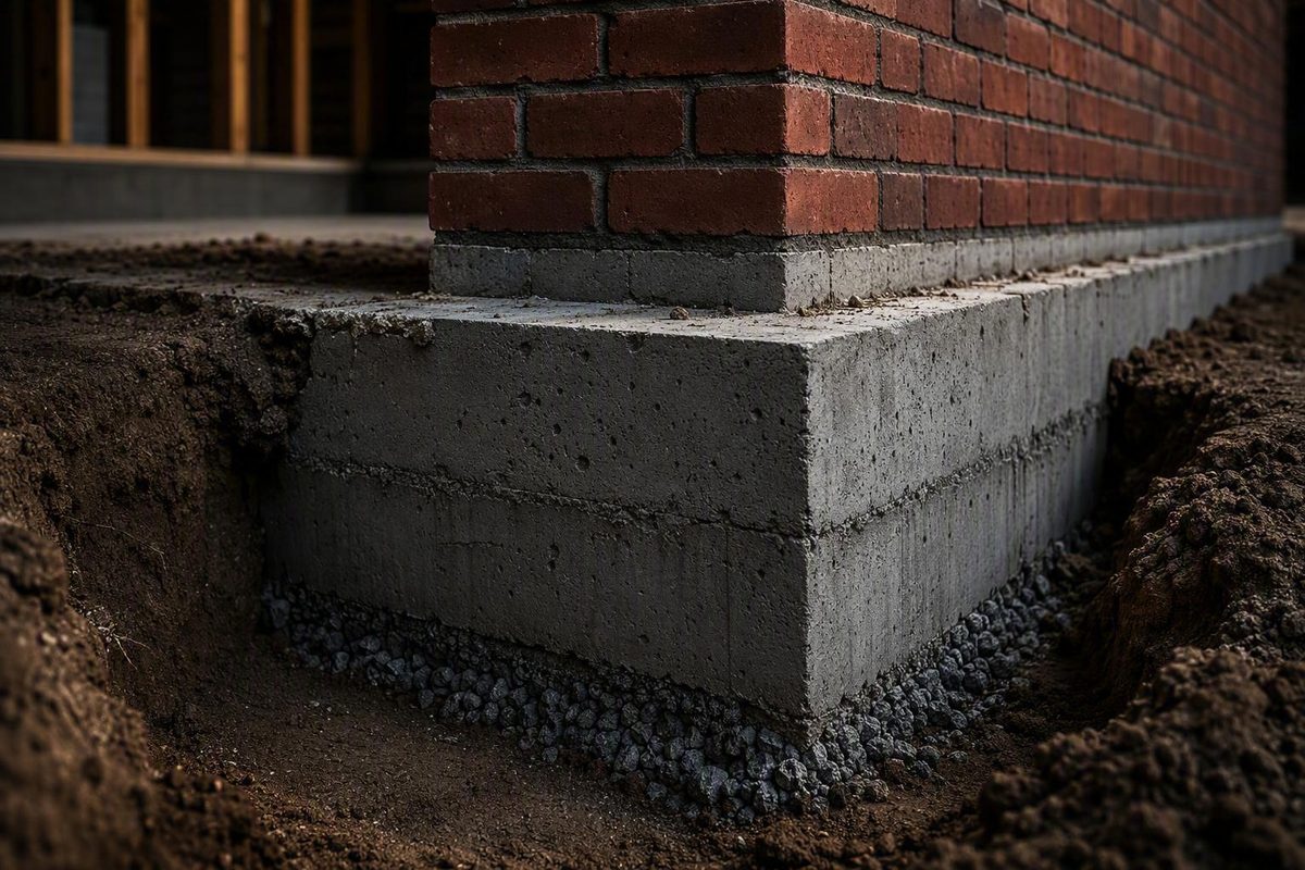
There is no universal width, thickness, or depth for a concrete foundation for a brick wall. Use this five-step sequence: identify the wall type; document its geometry and loads; establish soil conditions; check frost, weather exposure, and drainage requirements; then verify the design with the local authority or an appropriate structural or geotechnical professional. Wall thickness alone is not enough to select a safe footing.
The short answer: there is no universal footing size
A footing must support the wall’s vertical load and address applicable lateral forces, such as wind, retained-soil pressure, or loads transferred from a building. Its required dimensions depend on:
- Whether the brick is veneer, load-bearing masonry, freestanding construction, or part of a retaining wall
- Wall height, thickness, length, openings, piers, and lateral supports
- Loads from the wall, building, roof, snow, wind, retained soil, or nearby construction
- Allowable soil-bearing capacity and excavation conditions
- Frost depth, weather exposure, groundwater, and surface drainage
- The locally adopted code edition, amendments, permits, and inspections
The historical 2021 International Residential Code states the governing performance principle: foundations must accommodate imposed loads and transmit them to supporting soil. Within that chapter’s scope, exterior walls require continuous approved footing or foundation support founded on undisturbed natural soil or engineered fill. Its footing table for qualifying light-frame construction, including certain brick-veneer conditions, begins at 12 inches wide by 6 inches thick. That value is not a default for solid, freestanding, boundary, garden, or retaining walls; the listed dimensions change as loads rise or soil capacity falls (historical 2021 IRC, Chapter 4).
Because this is a historical model-code edition, do not assume it is enforceable where the wall will be built. Confirm the adopted edition, local amendments, frost requirements, permit threshold, required inspections, and building official’s interpretation before construction.
Identify the wall type before looking for dimensions
| Wall type | What must be evaluated? | Potential lateral support | Review questions |
|---|---|---|---|
| Brick veneer on a building | Veneer weight and applicable environmental loads | Ties and coordinated support from the building | Which veneer provisions apply, and what foundation or ledge supports it? |
| Solid load-bearing masonry | Wall weight and any building loads delivered to it | Floors, roofs, intersecting walls, piers, or designed connections | What loads reach the wall, and is project-specific engineering required? |
| Freestanding garden or boundary wall | Wall weight, wind, and overturning | Piers, returns, buttresses, or other designed elements | What permit, height, setback, wind, and engineering rules apply locally? |
| Retaining wall | Wall weight, retained-soil pressure, water, and possible surcharge | The complete wall-and-foundation system | What soil, drainage, slope, groundwater, and surcharge conditions govern? |
The supplied building-foundation provisions do not establish whether they apply to a particular freestanding garden or boundary wall. Ask the local authority how the proposed wall’s height, function, location, and relationship to property lines affect permits and design review rather than transferring a building-veneer table to the project.
Brick-veneer footing guidance does not resolve those conditions.
Before requesting a footing size, record:
- Intended wall function
- Overall height, thickness, and length
- Brick or masonry assembly type
- Openings and changes in height
- Dimensions and spacing of piers, returns, or other supports
- Connections to buildings or intersecting walls
- Whether either side retains soil
- Nearby slopes, pavements, structures, property lines, and foundations
Separate footing width, thickness, and embedment
“Footing size” can refer to several dimensions that should not be treated as interchangeable:
- Footing width is the horizontal dimension that distributes load over the supporting soil.
- Footing thickness is the vertical thickness of the concrete element.
- Embedment is the distance from finished grade to the bottom of the footing or foundation.
- Bottom-of-footing elevation is the level at which the footing bears.
- Frost-line depth is a local reference that may affect the required foundation depth.
A conceptual cross-section looks like this:
                           BRICK WALL
                              ││
                              ││  ← Wall position
Finished grade ───────────────││────────────────────
                              ││
                    Total     ││
                  embedment   ││
                              ┌─────────────────┐
                              │    CONCRETE     │ ↑
                              │     FOOTING     │ │ Footing
                              │                 │ ↓ thickness
                              └─────────────────┘
                               ↑ Bottom-of-footing elevation
                              ←── Footing width ─→

                         SUPPORTING SOIL
              Undisturbed natural soil or engineered fill


LOCAL FROST REFERENCE — VERIFY INDEPENDENTLY

Finished grade ─────────────────────────────────────
                  ↓ Locally required frost depth
                  ─ Local frost-line reference

Required relationship between frost depth and the footing
must be established from local provisions and the design.
Concept only; not to scale and not a construction detail.
A 6-inch concrete thickness means the concrete element itself is 6 inches thick. It does not mean the footing bottom may be only 6 inches below finished grade, and it does not demonstrate compliance with local frost requirements.
The historical 2021 IRC footing table begins at 12 inches wide by 6 inches thick only under its stated light-frame and brick-veneer conditions; it lists larger dimensions as loads increase or allowable soil capacity decreases (historical 2021 IRC, Chapter 4 footing table). Obtain the locally required minimum embedment, frost depth, and bottom-of-footing elevation separately.
How soil and loads change the footing
Footing width affects how much soil area receives the load. In basic terms, heavier loads or lower allowable soil-bearing capacity generally require more bearing area or an engineered alternative.
The historical IRC lists presumptive bearing values from 1,500 pounds per square foot for specified clay and silt soils to 12,000 pounds per square foot for crystalline bedrock. If soil with a bearing capacity below 1,500 psf is likely, the allowable capacity must be established through a soils investigation. The building official may also require testing where expansive, compressible, shifting, or otherwise questionable soil characteristics are indicated.
Consider two bounded scenarios:
- A short brick veneer supported as part of a light-frame building on verified competent soil may fit a prescriptive local-code pathway.
- A tall freestanding brick wall over uncontrolled fill combines uncertain bearing conditions with substantial lateral and overturning questions.
Pause footing selection and concrete placement rather than concealing the condition or improvising a repair. Ask the building official or an appropriate geotechnical or structural professional whether investigation or a revised design is required (historical 2021 IRC, Chapter 4 soil-test provisions).
Concrete exposure and drainage matter too
Concrete strength and durability are separate from footing geometry. A footing can have apparently adequate dimensions yet remain unsuitable if its concrete specification does not address weather exposure or applicable local requirements.
The historical code material specifies at least 2,500 psi concrete for some foundations not exposed to weather. For listed vertical exterior concrete exposed to weather, the specified values vary by weathering category and reach 3,000 psi; moderate and severe weathering categories also require air entrainment. The same chapter generally requires grade to fall at least 6 inches within the first 10 feet away from foundation walls. Where physical barriers prevent that fall, it permits alternatives including drains or swales and specifies a slope for nearby impervious surfaces. These are code-specific provisions, not a universal concrete mix or drainage design, as shown in the historical 2021 IRC Chapter 4 provisions.
Confirm the required compressive strength, exposure classification, air content where applicable, and placement and curing requirements for the actual project. Do not assume that ordering “standard footing concrete” settles those decisions.
Runoff should be directed away so it does not repeatedly saturate or erode soil beside the foundation. Where the ordinary grading pattern is obstructed, the drainage route must still lead to an approved collection point without creating another hazard.
General surface-grading provisions are not a retaining-wall drainage design. Drainage behind retained soil and groundwater control depend on project-specific information such as soil conditions, water levels, available outlets, wall configuration, and downstream effects.
Use this preconstruction verification checklist
Before excavation or concrete placement, confirm each applicable item:
- [ ] Wall classification: veneer, solid load-bearing masonry, freestanding wall, boundary wall, or retaining wall
- [ ] Geometry: height, thickness, length, openings, level changes, and pier or return locations
- [ ] Function and loads: what the wall supports and whether wind, retained soil, surcharge, or other lateral forces must be evaluated
- [ ] Lateral support: ties, returns, buttresses, intersecting construction, or designed connections
- [ ] Retaining conditions: retained-soil height, slope, groundwater, drainage route, and possible surcharge
- [ ] Bearing surface: undisturbed natural soil or engineered fill designed, installed, and tested appropriately
- [ ] Soil capacity: applicable allowable bearing value or a soil investigation where conditions are questionable
- [ ] Local rules: adopted code edition, amendments, permit threshold, setbacks, inspections, and building-official interpretation
- [ ] Depth requirements: local frost depth, minimum embedment, and required bottom-of-footing elevation
- [ ] Site conditions: wind, overturning, seismic conditions, flood exposure, steep slopes, erosion, and groundwater where relevant
- [ ] Adjacent work: nearby foundations, utilities, excavations, pavements, property lines, and structures
- [ ] Concrete specification: strength, durability, exposure, placement, and curing requirements
- [ ] Drainage: finished grading, runoff route, drains or swales where needed, and effects on neighboring property
- [ ] Inspections: required checks before concrete placement and before work is concealed
Reinforcement size, spacing, concrete cover, dowels, and wall-to-footing connections cannot be selected from the limited footing information presented here. Do not improvise them; they must come from applicable prescriptive provisions or a project-specific design.
Structural review is appropriate for tall or freestanding walls, retaining walls, significant lateral exposure, steep slopes, flood hazards, uncertain connections, or work near existing foundations. Geotechnical review is appropriate for uncontrolled fill, expansive or compressible soil, shifting ground, low bearing capacity, groundwater, or other questionable subsurface conditions.
Selecting a concrete foundation for a brick wall is a design process, not a lookup of one standard dimension. Classify the wall, distinguish width from thickness and embedment, establish soil and frost conditions, address concrete exposure and drainage, and obtain local approval or professional design when the project falls outside a straightforward prescriptive veneer application.