
A Concrete Masonry Unit Wall Is an Assembly, Not Just a Stack of Blocks
How to lay out and detail a CMU wall for structure, movement, moisture, insulation, openings and construction coordination.
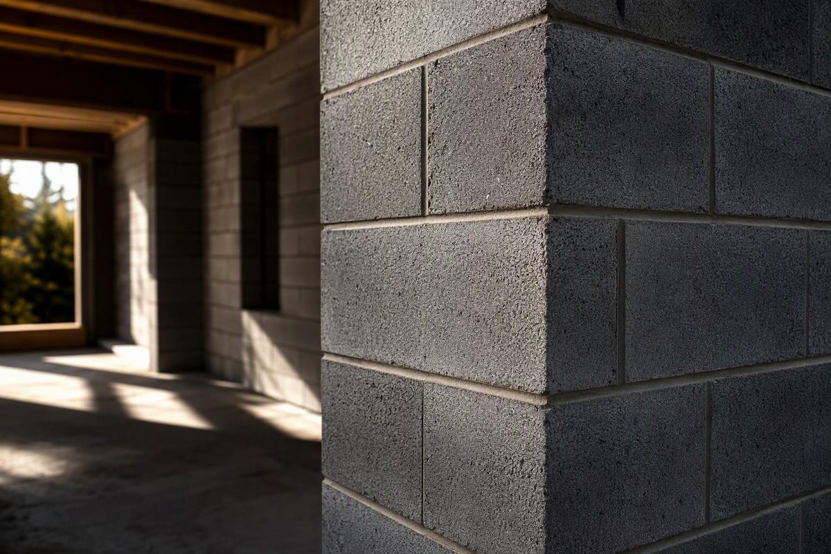
A concrete masonry unit wall can be a structural wall, an exterior enclosure, an interior partition, a veneer backup—or several of these at once. Its design is not settled by writing “8-inch CMU” on a plan. The drawings must coordinate unit dimensions, reinforcement, grout, openings, movement joints, moisture control, insulation and connections.
The first decision is the wall’s role. Everything else follows from it.
| Wall role | What the design must establish |
|---|---|
| Loadbearing wall | Gravity loads, out-of-plane loads, slenderness, bearing and connections |
| Shear wall | In-plane lateral loads, reinforcement, grout, collectors and diaphragm anchorage |
| Exterior single-wythe wall | Structure plus rain, air, vapor and thermal control at one masonry wythe |
| Backup wall | Structural support and attachment for a separate veneer or cladding system |
| Interior partition | Height, lateral support, deflection at the head, fire/acoustic requirements and services |
| Below-grade wall | Soil and surcharge loads, water management, drainage and foundation connection |
For a broader comparison with other unit-masonry systems, see masonry construction.
What makes up a CMU wall
The block is only one component. Mortar bonds units and seals their joints; grout fills selected or all cores; reinforcing steel carries specified tensile forces and adds ductility. The Concrete Masonry & Hardscapes Association (CMHA) explains that grout in reinforced masonry bonds the units and reinforcing bars so they act together under load. A partially grouted wall has grout in spaces containing reinforcement; a solidly grouted wall has every core filled (CMHA, “Grouting Concrete Masonry Walls”).
ASTM C90 is the most commonly encountered U.S. specification for dry-cast loadbearing CMU. The current ASTM page covers hollow and solid normal-, medium- and lightweight units suitable for loadbearing and nonloadbearing applications (ASTM C90-24a). The project must still cite the edition required by its adopted code and specifications.
Do not treat mortar, grout and concrete as interchangeable:
- Mortar creates bed and head joints between units.
- Grout is sufficiently fluid to fill cells and surround reinforcement without leaving voids.
- Concrete may form the footing, slab or other supporting work but is not a substitute for specified masonry grout.
Lay out the wall on the masonry module
The common nominal unit is 8 × 8 × 16 inches. Its specified dimensions are typically 3/8 inch smaller in each direction—7 5/8 × 7 5/8 × 15 5/8 inches—so the unit plus a 3/8-inch mortar joint occupies an 8-inch vertical by 16-inch horizontal module. CMHA distinguishes these nominal planning dimensions from specified unit dimensions and notes that other widths and face sizes are available (CMHA, “Concrete Masonry Unit Shapes, Sizes, Properties, and Specifications”). See standard CMU dimensions for the full nominal-versus-actual explanation.
That module should control more than the wall length. Coordinate:
- rough-opening widths and head heights;
- sill, bond-beam and bearing elevations;
- wall returns, piers and pilasters;
- vertical-bar cells and foundation dowels;
- electrical boxes, sleeves and larger penetrations;
- control joints and changes in unit finish.
A half-unit error on plan can become a cut block at every course, a misaligned reinforcing cell or an improvised jamb. Elevations should show the coursing rather than leaving the mason to reconcile nonmodular opening heights in the field.
CMHA describes a dry layout of the first course to check wall dimensions, openings and bond before mortar is placed. Its construction guidance identifies 3/8 inch as the typical bed- and head-joint thickness and says mortar should extend across the face-shell bedding surfaces of hollow units (CMHA, “Concrete Masonry Construction”).
Show the structural load path
A reinforced wall is not made structural merely by adding a general note for “rebar and grout.” The structural drawings should identify:
- wall thickness and specified masonry compressive strength;
- vertical-bar size and spacing;
- horizontal reinforcement or bond-beam locations;
- which cells are grouted, or whether the wall is fully grouted;
- bar laps, development and prohibited splice zones;
- jamb, corner, intersection and end-of-wall reinforcement;
- lintels and their bearing at openings;
- dowels and the wall-to-foundation connection;
- floor- and roof-diaphragm connections; and
- lateral support and deflection accommodation at the wall head.
TMS 402 establishes masonry design and construction provisions intended for code adoption, while TMS 602 establishes minimum construction requirements. The Masonry Society says its 2022 standards form the basis for masonry provisions in the 2024 International Building Code; the governing edition nevertheless depends on local adoption and the contract documents (The Masonry Society).
Cell congestion must be checked in section, not just in a bar schedule. Reinforcement, laps, anchors and embedded items need enough clear space for grout to flow and consolidate. CMHA states that mortar projecting more than 1/2 inch into a grout space must be removed because it can obstruct grout flow and cause bridging; vertical cores also need to align as continuous, unobstructed spaces (CMHA grouting guidance). Open-end units, bond-beam units and lintel units may solve conditions that a standard two-cell block cannot.
Control water as an assembly
A single-wythe exterior CMU wall has no continuous drainage cavity, so water resistance requires particular attention. CMHA identifies three levels of defense: surface protection, internal protection such as integral water repellents, and drainage or drying through flashing, weeps and vents. It recommends redundancy, while also noting that not every measure applies to every wall (CMHA, “Design for Dry Single-Wythe Concrete Masonry Walls”).
Detail the wall base, sills, lintels, roof intersections, parapets, penetrations and control joints. Where flashing and weeps form part of the drainage strategy, show how the flashing turns up, terminates and drains, and keep mortar droppings from blocking cells or weeps. Fully grouted single-wythe walls are instead commonly designed as barrier walls; CMHA notes that flashing is unnecessary in that construction and that introducing it can affect shear transfer. The structural engineer should evaluate the selected detail.
Integral water repellent is not a replacement for joints, flashing where used, or workmanship. CMHA notes that it reduces absorption but has little effect on water entering through cracks and voids. If water-repellent CMU is specified, compatible water repellent should also be used in the mortar (CMHA).
A cavity wall or veneer over CMU uses a different strategy: the exterior wythe sheds most rain, while the cavity, flashing and weeps manage what passes through. Coordinate ties, cavity width and drainage with the masonry ties and masonry veneer details.
Separate crack control from structural reinforcement
Concrete masonry undergoes a small net volume reduction from moisture, temperature and carbonation effects. Where foundations, corners, diaphragms or adjacent materials restrain that movement, tensile stress and cracking can result. Control joints divide a long wall into panels that can shorten with less restraint; horizontal reinforcement can help control shrinkage cracking. Neither should be located by a generic spacing note alone.
CMHA recommends joints where stress concentrations are expected and distinguishes a CMU control joint from the expansion joint used primarily to accommodate clay-masonry expansion. It identifies support deflection, foundation settlement and differential movement with steel or brick as separate crack sources (CMHA, “Crack Control Strategies”).
Coordinate control joints with the structural engineer. A joint can interrupt a shear wall, bond beam, lintel or diaphragm load path. Show which reinforcement stops, which crosses, how lateral stability is maintained and how the exterior sealant joint remains continuous.
Openings concentrate stress and interrupt both reinforcement and drainage. The jamb, lintel, sill, flashing, sealant and nearby control joint should therefore be drawn as one condition—not scattered among unrelated details.
Use assembly values for thermal, fire and acoustic performance
Hollow CMU is not thermally uniform. Face shells and webs conduct heat differently from insulated cores, while grouted cells create stronger heat-flow paths. CMHA’s calculation method accounts for web configuration and uses an area-weighted approach for partially grouted walls (CMHA, “R-Values and U-Factors of Single-Wythe Concrete Masonry Walls”). Verify the whole-wall U-factor using the actual unit configuration, density, grout pattern, insulation and finishes. Where practical, continuous insulation reduces the effect of masonry webs and grouted cells; see continuous insulation for the transitions that can undermine it.
Do not assign a fire rating from nominal wall thickness alone. CMHA identifies tested assemblies, calculated ratings and prescriptive code assemblies as distinct compliance paths. Calculated CMU ratings depend substantially on aggregate type and the unit’s equivalent thickness—the thickness obtained if the concrete in a hollow unit were recast without cores—not simply its nominal width (CMHA, “Fire Resistance of Concrete Masonry Construction”). Penetrations, joints and wall-to-structure conditions must preserve the selected assembly.
Acoustic performance is also an assembly property. CMHA states that sound transmission class varies with wall weight, construction and finishes; its design guidance calls for sealing joints and penetrations so gaps do not undermine the wall’s sound isolation (CMHA, “Sound Transmission Class Ratings for Concrete Masonry Walls”). Specify a tested or calculated assembly rather than assuming an STC from nominal block width.
What a coordinated CMU wall detail should show
Before issuing drawings, check that plans, elevations, sections and specifications agree on:
- nominal wall thickness, unit type, density and exposed finish;
- module, coursing and opening dimensions;
- mortar type, joint profile and color;
- masonry strength, reinforcement and grout extent;
- lintels, bearing and temporary-shoring responsibility;
- control-joint locations and continuity;
- flashing, weeps, sealants and water repellents where applicable;
- insulation, air barrier and vapor-control continuity;
- veneer ties, shelf angles or cladding attachments where applicable;
- foundation dowels and floor/roof anchorage;
- firestopping and rated-joint systems; and
- embedded services, sleeves and prohibited cutting zones.
A successful concrete masonry unit wall is resolved at its interfaces. The field can build a clean modular wall only when the drawings reconcile structure, enclosure and services before the first course is laid.