
How to Carry the Thermal Layer Across the Whole Wall
Screws, nails, clips, girts, shelf angles, masonry ties, balconies, canopies, penetrations, and service openings can conduct heat through or around it.
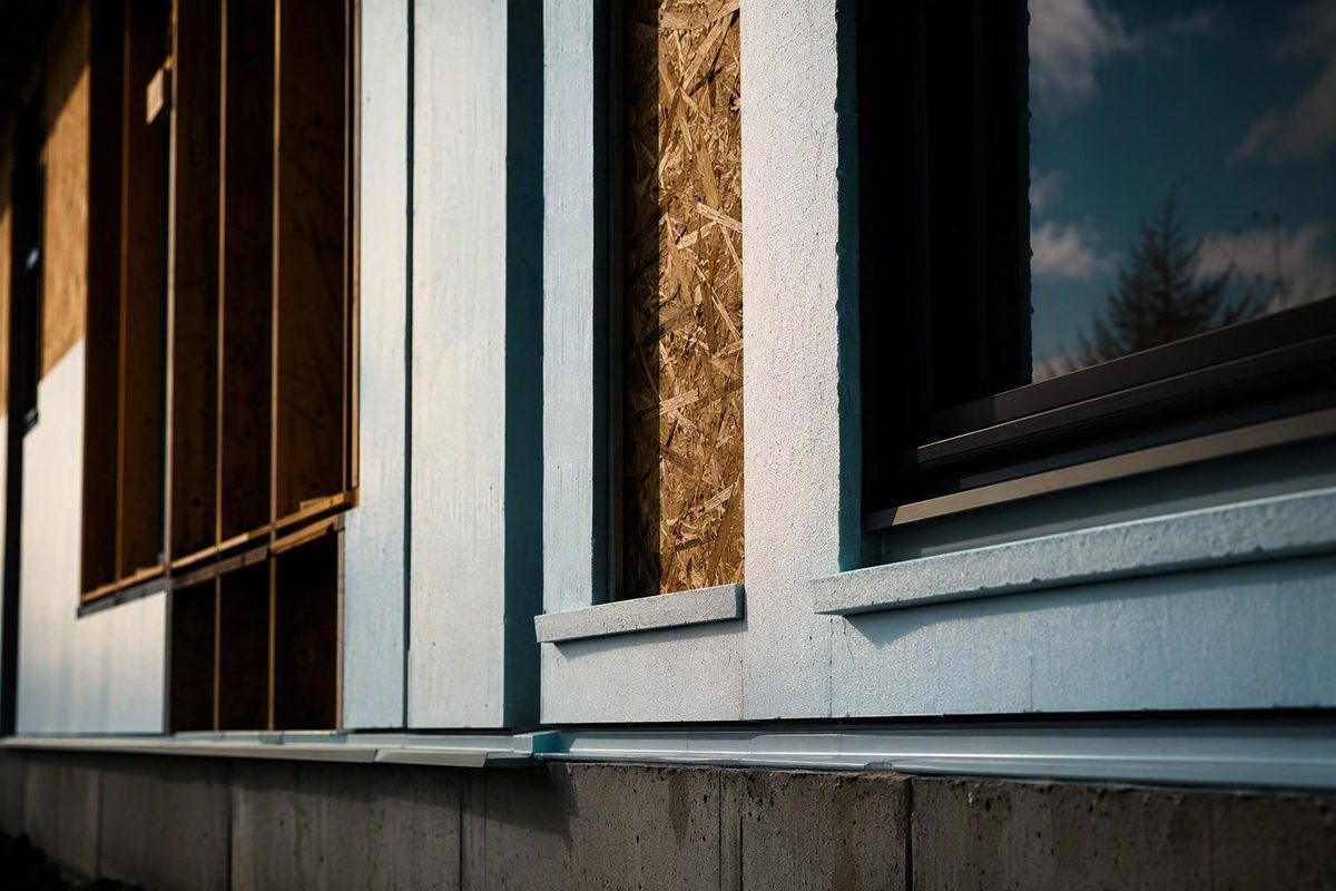
Continuous insulation is often drawn as one clean band outside the sheathing. In a finished building, that band must negotiate studs, slab edges, windows, doors, fasteners, girts, masonry supports, roof transitions, foundations, utilities, and cladding attachments. Its success therefore depends less on adding “an extra board” than on coordinating the entire wall.
The central thermal idea is straightforward: cavity insulation fills the spaces between framing members, while continuous insulation crosses the framing and reduces the conductive paths that remain. Thermal performance, however, is only one part of the design. Air leakage, rain control, drainage, vapor movement, fire exposure, window flashing, structural attachment, product compatibility, and construction sequencing still have to be resolved.
What continuous insulation means—and what it does not
A recognized definition describes continuous insulation as insulation that crosses structural members without thermal bridges other than fasteners and service openings. It may be installed on the interior, exterior, or integrally within an opaque building-envelope surface. That definition identifies both the intent—crossing the structure—and the accepted limits to continuity. The ASHRAE 90.1 definition quoted by Insulfoam includes those locations and exceptions.
Cavity insulation and continuous insulation describe different relationships to the structure:
- Cavity insulation occupies the spaces between structural framing members such as wood or metal studs and joists.
- Continuous insulation extends across the framing as well as the insulated cavities.
- Combined assemblies use both, allowing the cavity layer to provide part of the thermal resistance while the continuous layer reduces the framing penalty.
- Insulation interrupted by exterior clips, girts, or sub-framing is not necessarily equivalent to ordinary cavity insulation. Those attachment components can create additional thermal bridges that must be included in assembly analysis.
“Continuous” does not mean perfectly free of thermal bridges. Screws, nails, clips, girts, shelf angles, masonry ties, balconies, canopies, penetrations, and service openings can still conduct heat through or around the insulation. Some are small and dispersed; others are concentrated metal connections that can materially affect the wall. Drawings should identify these residual bridges rather than assuming that a colored insulation line has eliminated them.
Continuous insulation is also an assembly strategy, not a single product category. Depending on the wall, it may use EPS, GPS, XPS, polyisocyanurate, mineral-wool board, spray-applied foam, insulated structural sheathing, or another approved system. The same material can behave differently when its thickness, facer, density, temperature, exposure, fasteners, or joint treatment changes.
Exterior placement is the most familiar approach because it can cover studs, rim areas, and sheathing from outside. Interior continuous insulation can also cross framing, particularly in renovation or solid-wall construction, but it consumes interior space and changes the moisture and service-cavity strategy. Integral systems incorporate insulation into panels or another opaque envelope component.
Most importantly, an insulation layer is not automatically all of the following:
- A thermal-control layer
- An air barrier
- A water-resistive barrier, or WRB
- A drainage plane
- A vapor-control layer
Some products can perform more than one role. Certain foam-plastic sheathing systems, for example, may be detailed as insulation plus an air- or water-control layer. That capability is conditional on the exact product, approvals, seams, tapes, transitions, penetrations, and installation—not a general property of continuous insulation. The Continuous Insulation with Foam Sheathing resource describes these as system-dependent functions.
A board can resist heat flow while allowing air through its joints. A taped surface may look continuous but fail at a rough opening, parapet, pipe, or foundation transition. Each required function must therefore be named and traced independently.
Why framing changes whole-wall thermal performance
A thermal bridge is a comparatively conductive path that interrupts or bypasses the primary insulation. In a framed wall, studs are not isolated anomalies; they repeat across the elevation. Plates, headers, corners, blocking, lintels, shelf angles, and floor lines add further paths.
Heat consequently follows parallel routes:
- Through insulated cavities
- Through framing and structural connections
- Through sheathing and interior finishes
- Through clips, girts, ties, and fasteners
- Around openings and at wall transitions
The R-value printed on a batt describes that insulation under defined test conditions. It does not describe the complete wall. A cavity-insulated wall includes less-resistant framing paths, and its whole-wall performance also reflects the other layers and connections. Comparing walls only by batt labels can therefore obscure substantial assembly differences.
R-value expresses resistance to heat flow: under the defined conditions, higher resistance means less heat transfer. U-factor expresses the rate of heat transfer through an assembly: lower is better. Parallel heat-flow paths and repeating bridges must be represented appropriately.
Placing insulation across the framing raises resistance along the stud path as well as the cavity path. It therefore reduces the contrast between those paths and improves whole-wall thermal performance.
That improvement is not a moisture guarantee. Condensation risk still depends on outdoor climate, indoor temperature and humidity, air leakage, vapor permeance, the relative position and amount of insulation, thermal bridges, rain exposure, and workmanship. Air leakage is a separate moisture pathway, so a wall with generous exterior insulation but a discontinuous air barrier can remain vulnerable.
Energy-compliance software also distinguishes cavity and continuous insulation. The U.S. Department of Energy explains that REScheck accepts separate cavity and continuous R-value inputs for framed walls and uses those values within its wall-modeling assumptions. For an unusual wall or one with incompletely filled cavities, the guidance directs users toward the “other” wall type and a calculated overall U-factor rather than forcing the assembly into a standard cavity-wall model. DOE’s REScheck FAQ describes these inputs and modeling limits.
That distinction matters during estimating and design review. “R-20 plus R-5 continuous” is not interchangeable with “R-25 in the cavity,” even if the nominal sum looks similar. The first arrangement places resistance across the framing; the second does not. Nor should a REScheck assumption be treated as a measured description of every built wall. Complex girts, shelf angles, penetrations, partial coverage, and concentrated bridges may require more detailed analysis.
The wall is a system: map every control layer
A practical continuous-insulation wall may contain:
- Interior finish and service space
- Structural framing or a mass-wall substrate
- Cavity insulation, where used
- Structural sheathing
- An air-control layer
- A WRB or other bulk-water-control layer
- Flashings and transition membranes
- Continuous insulation
- Fasteners, washers, clips, girts, or furring
- A drainage or ventilation space
- Exterior cladding
- Sealants, tapes, gaskets, and termination accessories
The order varies. What must not vary is the design team’s ability to identify which component performs each required function and how that function continues through transitions.
Separate the five control functions
Thermal control limits conductive heat flow. Continuous insulation strengthens this layer by carrying it across framing, but attachments and transitions remain relevant.
Air control limits uncontrolled airflow through the enclosure. It depends on a continuous, durable plane connected at joints, openings, penetrations, roofs, floors, and foundations.
Bulk-water control sheds rain and directs incidental water outward. The WRB, flashings, end dams, laps, and opening details must form a coherent path.
Drainage provides a route and space for water to move down and out.
Vapor control manages diffusion and drying potential. It is governed by material permeance, thickness, facers, climate, indoor conditions, and layer sequence—not by the insulation’s generic name.
A product may serve multiple functions only when it is approved and detailed for each one. If a foam facer is designated as the WRB, the specification must also address compatible tape, substrate preparation, permissible joint conditions, application pressure, penetrations, terminations, flashing integration, repairs, and weather limits. If the same surface is intended as the air barrier, transitions to adjacent air-control materials require equal attention.
Do not label a taped board “WRB/AB” merely because its face appears impermeable. Product documentation and applicable approvals must support those uses, and the constructed assembly must preserve continuity.
Components are not automatically interchangeable
Substituting one board, tape, fastener, washer, WRB, or sealant can change:
- Adhesion and primer requirements
- Vapor permeance and drying direction
- Drainage geometry
- Required fastener length or capacity
- Insulation compression
- Fire-performance status
- Compatibility with asphaltic or solvent-containing materials
- Coverage under evaluation reports or tested assemblies
- Installation temperature and sequencing
A substitution review should compare functions, approvals, and interfaces—not just dimensions or nominal R-value. A component that appears equivalent in isolation may change the performance or documented status of the complete assembly.
Drafting brief for the wall section
At minimum, the architectural wall section should label:
- Interior finish and any service cavity
- Structural framing or substrate
- Cavity insulation
- Sheathing
- Air-barrier plane
- WRB or bulk-water-control plane
- Continuous-insulation material and thickness
- Fasteners, washers, clips, and attachment substrate
- Furring, sub-framing, or drainage space
- Exterior cladding
Use distinct line types or colors for thermal, air, water, drainage, and vapor functions. Continue those lines through an enlarged window head, jamb, and sill; an outside corner; the base of wall; a roof or parapet transition; and a representative penetration.
The detail set should show where one product hands a function to another. A membrane-to-sheathing transition at grade, for example, deserves more attention than the uninterrupted center of a board. The same is true at rough openings, shelf angles, exterior fixtures, louvers, scuppers, balcony connections, and changes in cladding.
Comparing foam board, mineral wool, spray foam, and insulated sheathing
Material selection should begin with the proposed wall, not a ranking of nominal R-values. The table below is a screening tool rather than a specification.
All figures are approximate and commercially reported. Insulfoam reports about R-3.9 per inch for its cited one-pound-density EPS condition and R-5 per nominal inch for its cited GPS category. Those values are subject to the product qualifications in Insulfoam’s comparison. Grip-Rite reports approximately R-5 per inch for XPS, up to an aged R-6.5 per inch for polyiso, and roughly R-4 to R-4.3 per inch for mineral-wool board. Grip-Rite’s guide also notes that product, thickness, temperature, aging, density, and test conditions affect performance.
| Material or system | Approximate source-reported thermal resistance | Vapor behavior | Combustibility and fire implications | Moisture considerations | Thickness and compressibility | Attachment implications | Possible WRB integration | Installation demands |
|---|---|---|---|---|---|---|---|---|
| EPS | About R-3.9/in. for the cited one-pound-density condition | Often more vapor-open than other common rigid foams, but density, thickness, and facers matter | Foam-plastic requirements must be checked for the exact assembly | Joints, exposure, drainage, and facer must be resolved | Rigid; available in multiple densities and generally thicker than higher-R foam for the same nominal resistance | Does not replace an approved structural nailing base | Only with a product and joint system approved for that role | Requires a flat substrate, fitted joints, protected edges, and compatible seam treatment |
| GPS | About R-5 per nominal inch for the cited category | Product-specific; facers and thickness matter | Foam-plastic requirements must be checked | Verify water exposure, joints, and drying strategy | Rigid; the cited value may permit less thickness than the cited EPS condition | Long fasteners or sub-framing must transfer loads to structure | Product-specific | Similar coordination to other rigid foam boards |
| XPS | About R-5/in. in the cited guide | Relatively vapor-resistant in the cited comparison; thickness matters | Foam-plastic requirements must be checked | Board joints and the water-management plane remain critical | Rigid and comparatively resistant per inch in the cited guide | Limited nail-holding capacity; structural attachment generally bypasses it | Some approved systems permit taped-board WRB use | Requires coordinated seams, flashing, penetrations, and attachment |
| Polyisocyanurate | Up to an aged R-6.5/in. in the cited comparison | Foil-faced products can be low-permeance; other facers differ | Foam-plastic and assembly fire requirements must be checked | Temperature, aging convention, facer, joints, and exposure affect selection | High reported resistance per inch can limit wall thickness | Fasteners and furring must transfer cladding loads to approved structure | Some faced products may serve as a WRB when specifically approved | Requires product-specific tapes, seam preparation, protection, and transitions |
| Mineral-wool board | About R-4 to R-4.3/in. in the cited guide | Generally vapor-open | Commonly described as noncombustible, although the complete wall still requires review | Can support outward drying but does not replace a WRB or drainage strategy | Thicker and compressible | Washer size, furring, fastener design, and tightening are important | Usually paired with a separate WRB at the substrate | Requires close-fitting boards, controlled compression, aligned furring, and careful flashing |
| Spray foam | Product- and formulation-specific; no universal value used here | Open- and closed-cell formulations differ substantially | Protection and assembly requirements depend on the exact use | Substrate condition, continuity, curing, and concealed conditions matter | Conforms to irregular surfaces; installed thickness must be verified | Does not by itself resolve cladding attachment | Barrier functions are formulation- and approval-specific | Requires specialized equipment, substrate control, thickness verification, and qualified application |
| Insulated structural sheathing | Product-specific composite value | Depends on the foam core, wood layer, facer, and seams | Requirements apply to the exact composite assembly | Edge exposure, joint sealing, and factory layers require coordination | Consolidates layers but comes in defined panel configurations | Provides structural or nail-base functions only as approved | Some products include a factory-applied WRB | Requires proprietary fastening, joint, tape, sealant, and bracing details |
The figures should not be treated as category-wide design values. Manufacturer data for the exact product, density, thickness, service temperature, facer, moisture condition, aging convention, and applicable test method should govern.
Foam board
Their differences matter, however. EPS, GPS, XPS, and polyiso do not share one vapor profile, temperature response, facer, or joint system.
The design must answer:
- Is the board only thermal insulation, or also an approved WRB or air-barrier component?
- How will seams be treated?
- Where can the wall dry?
- What fire protection or documented assembly is required?
- How do cladding loads reach structure?
- Are tapes, sealants, and flashings compatible?
- How are exposed edges protected during construction?
Mineral wool
Mineral-wool board is generally vapor-open and commonly described as noncombustible. Those properties can be useful where outward drying or reduced combustible content is important. The tradeoff is usually greater thickness for the same nominal thermal resistance, plus compressibility that affects attachment.
Fasteners and washers must hold boards securely without crushing them. The WRB is commonly located at the sheathing or structural wall, where window flashing can integrate directly with it.
Spray foam
Spray foam can form a continuous layer over irregular substrates or framing, but “spray foam” is not one material. Formulation, density, cell structure, thickness, substrate condition, curing, and protection requirements all affect performance. Advanced Architectural Products states that spray-foam installation requires specialized equipment and installer certification; the applicable program and manufacturer requirements should be confirmed for the project. Its overview lists spray foam among several continuous-insulation options.
Avoid assigning universal air-, vapor-, or water-barrier properties to spray foam. Those roles depend on the exact product, installed thickness, adhesion, transitions, penetrations, and approvals.
Insulated structural sheathing
Composite panels can combine structural sheathing, insulation, and sometimes a factory-applied WRB. It can also create dependence on proprietary fasteners, seam treatments, bracing limits, and repair procedures.
Confirm separately whether the selected panel provides:
- Required structural capacity or bracing
- The specified continuous R-value
- An approved WRB
- Air-barrier capability
- A suitable cladding nail base
- Compatibility with opening and flashing details
There is no universal winner. The best choice is the one that fits the climate, fire exposure, wall thickness, cladding, labor, availability, moisture strategy, product approvals, and attachment design of the actual project.
Choose the assembly by climate, moisture behavior, fire exposure, and code
Use a decision sequence rather than selecting a material first and designing around it later.
1. Identify the adopted code and climate zone
Establish the applicable energy, building, residential, and fire-code editions; local amendments; project occupancy; height; construction type; and enforcement interpretations. Requirements vary by jurisdiction and may differ between prescriptive and performance paths. Grip-Rite’s code overview likewise advises checking current adoption and local amendments with the building department rather than relying on a generic national summary. Its discussion references the 2021 model codes but does not establish what any jurisdiction has adopted.
2. Establish required thermal performance
Determine whether compliance is based on cavity and continuous R-values, an assembly U-factor, energy modeling, or another approved path. Do not import a continuous R-value from a national summary without checking the governing edition, wall type, exceptions, and local amendments.
3. Document framing and cavity insulation
Record stud material, depth, spacing, framing fraction where needed, cavity fill, headers, slabs, shelf angles, and other repeating bridges. A highly conductive steel-framed wall and a wood-framed wall with the same cavity label will not have the same whole-wall performance.
4. Locate every control layer
Select the air-, water-, drainage-, and vapor-control planes. Determine how each connects at roofs, floors, openings, foundations, and penetrations. Then assess how insulation placement changes temperatures and drying conditions.
Low-permeance insulation can restrict drying through one side of the wall. More vapor-open insulation may preserve greater outward drying potential but still requires rain control. Neither condition is inherently safe or unsafe; the result depends on the complete assembly.
Exterior insulation can warm inward layers during cold weather and reduce condensation potential. The amount needed for a particular moisture objective is climate- and assembly-specific. Indoor humidity, air leakage, cavity insulation, exterior temperature, material permeance, and thermal bridges all affect the result.
5. Identify fire and cladding constraints
No single generic detail resolves every wall. The project team must verify the applicable code provisions, product limitations, and tested or evaluated construction.
NFPA 285 addresses fire-propagation characteristics of applicable exterior non-load-bearing wall assemblies containing combustible components. It evaluates an assembly rather than granting blanket approval to an individual board, tape, or cladding. TruFast’s technical overview summarizes NFPA 285 in the context of coordinated exterior-wall components.
Changing insulation, WRB, air-barrier material, cladding, cavity depth, attachment system, or joint treatment may affect whether documented assembly evidence remains applicable. Avoid relying on a broad statement that a product by itself is “NFPA 285 compliant.”
6. Compare materials and attachment systems
Only after the preceding decisions should the team compare insulation products. Include available thickness, thermal behavior, permeance, fire status, moisture exposure, compressibility, attachment, labor, sequencing, availability, and compatible accessories.
Before issue for permit or construction, verify:
- Current local code adoption and amendments
- Climate zone and energy-compliance path
- Occupancy, height, and construction type
- Wall framing and cladding type
- Required fire-tested or evaluated assembly
- Product evaluation reports and limitations
- Structural attachment design
- Compatibility of tapes, sealants, membranes, and facers
- Review requirements of the authority having jurisdiction
Place the WRB and detail windows as one drainage strategy
The WRB may be behind the continuous insulation, over it, or integrated into an approved insulation or sheathing system. None of these arrangements is universally correct.
WRB behind the insulation
Locating the WRB at the sheathing creates a protected drainage plane close to the structure.
The design must still drain water that reaches the WRB. Flashings need to project or transition through the insulation, and exterior layers must not trap water at horizontal interruptions.
WRB over the insulation
An outboard WRB can align with exterior-positioned window flanges and simplify direct flashing integration. It may also place the primary water-control layer immediately behind a drainage cavity.
The insulation must provide adequate support for WRB fastening and detailing, or the fasteners must reach framing or approved nail-base sheathing. The sequence must protect the WRB from damage during furring and cladding installation.
Integrated WRB
Some insulated sheathing or foam-board systems permit the panel face and treated joints to function as the WRB. This can consolidate layers, but only if the exact product supports that use. Approved tapes, sealants, corners, transitions, fastener treatment, and opening details become part of the water-control system.
Let window position guide the detail
Exterior-aligned windows can place the flange near the outer insulation face. This may simplify flashing to an outboard WRB, but the flange needs approved support and adequate fastener penetration. Bucks may be required to provide a solid fastening surface.
Recessed windows place the unit closer to the structural wall. A WRB behind the insulation may provide the most direct connection between the window flashing and drainage plane. The sill must carry water outward across the depth of the insulation and cladding.
Intermediate windows require deliberate transitions between planes. They may reduce the visual depth of an exterior recess but often create more complicated jamb, sill, flange-support, and flashing conditions.
A DuPont bulletin for specified residential products recommends keeping its WRB in the same plane as the window flanges where possible. It allows the WRB over or under the listed continuous insulation for certain exterior-aligned conditions, while directing the WRB behind the insulation for its recessed-window details. The bulletin also calls for exterior-grade jamb extensions, outward-sloped sill extensions, and fasteners that satisfy the window manufacturer. Those instructions are limited to the products, building types, and conditions covered by the DuPont bulletin.
Four foam-sheathing approaches
Industry guidance identifies four typical approaches for flanged windows in walls where taped foam sheathing serves as the WRB:
- Standard method: flange mounted directly over the foam
- Picture-frame method: flange supported by a framed perimeter
- Window-buck method: a more developed support and return around the opening
- Rainscreen method: flange and furring coordinated with the exterior support plane
The resource describes its standard method for up to 1½ inches of foam, picture-frame applications commonly from ¾ to 1½ inches, and window-buck methods as most common where foam exceeds roughly 1½ to 2 inches. These are bounded associations from that guidance, not universal thresholds. The window-installation resource also states that multiple support and weather-resistance methods may be acceptable.
Insulation thickness alone does not decide whether a buck is required. Window type, flange geometry, manufacturer instructions, wind load, fastener capacity, substrate, WRB location, exterior trim, and construction sequence also matter.
Flashing must remain continuous from the window to the selected drainage plane without reverse laps, unsealed corners, or dead-end pockets. Window and system manufacturers govern flange support, fastener penetration, compatible tapes and sealants, and installation sequence.
Transfer cladding loads without crushing the insulation or breaking continuity
Continuous insulation separates cladding from the structural wall. That distance has to be crossed by an intentional load path.
Rigid foam generally has little nail-holding capacity and should not be treated as the structural nailing base for a WRB, furring, or cladding unless a specific composite product is approved for that function. A common arrangement is:
- Cladding attaches to furring, rails, clips, or approved sub-framing.
- The sub-framing bears against or passes over the insulation.
- Long fasteners pass through the insulation and sheathing.
- Fasteners engage framing or another approved structural substrate.
The attachment design should account for:
- Total thickness of insulation, sheathing, membranes, furring, and intervening layers
- Structural substrate and its condition
- Required fastener engagement
- Furring size, orientation, and spacing
- Cladding dead load
- Positive and negative wind pressures
- Fastener bending and withdrawal
- Corrosion exposure and material compatibility
- Insulation compressibility and allowable deformation
- Edge distances and framing location
- Limitations associated with documented fire or wall assemblies
Do not derive a generic fastener schedule from insulation thickness alone. Lightweight siding over rigid foam and a heavy panel system over thick mineral wool impose different loads and deformation limits.
Mineral wool and other compressible products require particular attention to washers, furring, and tightening. Over-compression reduces installed thickness and can create uneven resistance. Overdriven fasteners through compressible layers may also contribute to siding dimpling or distorted cladding.
Hammer & Hand recommends installing rigid foam thicker than 2 inches in multiple layers with staggered seams to reduce aligned joints and thermal bypass. Treat this as a contractor best-practice option subject to the product and project—not as a universal code rule. The same guide calls for manufacturer or project-specific fastening instructions and rolled tape seams to reduce fish-mouthing.
Field quality matters as much as the nominal assembly. Watch for:
- Open or misaligned board joints
- Fish-mouthed, wrinkled, or poorly bonded tape
- Dusty, wet, frozen, or incompatible substrates
- Missing primer where required
- Unsealed fastener or service penetrations
- Reverse-lapped flashing
- Unsupported membrane edges
- Gaps at corners and opening returns
- Crushed insulation beneath washers or furring
- Thermal bypasses at blocking and transitions
- Furring that misses framing or wanders out of plane
ASTM E2357 is cited in exterior-wall guidance as addressing air leakage through an air-barrier assembly, including representative penetrations. ASTM E331 is cited there as a pressure-differential water-penetration test. Their current scopes and suitability for the proposed specimens should be confirmed from ASTM; neither supplies a project-specific cladding-fastening schedule. TruFast summarizes the tests as part of its broader assembly-coordination guidance.
Installation inspection checklist
Before concealment, inspect and document:
- Substrate condition and repairs
- Correct insulation type, thickness, orientation, and facer
- Fastener type, corrosion resistance, length, location, and quantity
- Required engagement with framing or structural substrate
- Washer seating and insulation compression
- Board-joint fit and stagger where specified
- Tape adhesion, rolling, laps, and repairs
- WRB and air-barrier continuity
- Window, door, base, and penetration flashing
- Outward drainage at sills and horizontal interruptions
- Furring dimensions, spacing, alignment, and attachment
- Drainage-space continuity and ventilation openings
- Cladding fasteners and engagement
- Conformance with approved substitutions, mockups, and documented assemblies
Plan new construction and retrofits before ordering materials
In new construction, continuous insulation should be resolved in the wall section, opening schedule, structural details, specifications, and shop-drawing review before procurement.
The coordinated documents should show:
- Framing and structural sheathing
- Cavity insulation
- Each control layer and its function
- Continuous-insulation material and thickness
- Window and door position
- Bucks, bump-outs, jamb extensions, and sill extensions
- Head, jamb, and sill flashing
- Furring, clips, rails, or sub-framing
- Cladding and drainage space
- Structural fastening substrate
- Roof, foundation, balcony, and floor-line transitions
- Utility penetrations and exterior fixtures
A continuous-insulation package ordered before these decisions are complete can lock the project into the wrong panel thickness, fastener length, window geometry, or cladding return.
Begin retrofits with investigation
Existing walls demand selective demolition and verification. Record:
- Framing or masonry type
- Sheathing condition
- Previous additions and alterations
- Existing cavity insulation
- Interior vapor-control layers
- WRB and flashing condition
- Air-leakage paths
- Water staining, rot, corrosion, or mold
- Existing drainage cavities and weep paths
- Structural defects and loose substrates
- Window installation and replacement history
Removing cladding provides an opportunity to find concealed water and structural damage. Repair those conditions before covering the wall with new control layers. Adding insulation over a wet, deteriorated, or poorly drained assembly can conceal rather than solve the problem.
Where improved airtightness is a project goal, blower-door testing can help establish baseline leakage and identify priorities. A practitioner retrofit guide likewise recommends investigating the existing wall and considering blower-door testing before finalizing an exterior-insulation plan. That guidance is practical rather than a substitute for project-specific analysis.
Preserve intentional masonry drainage
Do not treat every apparent void as an insulation cavity. Solid masonry and multi-wythe walls may contain narrow drainage spaces, and brick veneer relies on a cavity that drains water behind the exterior wythe. Filling or blocking these paths can interfere with the wall’s water-management strategy.
Natural Resources Canada cautions that small cavities in some solid walls function as drainage planes and should not be insulated or have their drains blocked. It gives the same warning for the drainage space behind brick veneer. Its wall-retrofit guide also advises correcting moisture and structural problems before insulating.
Coordinate the new wall thickness
Exterior insulation moves the cladding plane outward. Check its effect on:
- Existing windows and doors
- Roof overhangs, rake edges, and kick-out flashing
- Parapet and coping widths
- Foundation ledges and base flashing
- Decks, stairs, porches, and rail attachments
- Utility meters, hose bibs, vents, and conduits
- Exterior lights, signs, cameras, and fixtures
- Louvers and mechanical penetrations
- Cladding returns at openings
- Property-line or zoning constraints
- Snow, splashback, and grade clearances
Interior continuous insulation has a different coordination burden. It can reduce room area, cover historic finishes, alter electrical and plumbing locations, and complicate floor, partition, and ceiling transitions. It also changes the temperature and vapor behavior of the existing wall, so the complete assembly should be evaluated before work begins.
Preconstruction checklist
Before releasing materials, confirm:
- Adopted codes, amendments, and compliance path
- Target cavity, continuous, and whole-wall performance
- Product approvals and evaluation reports
- A diagram identifying all five control functions
- Fire-tested or evaluated assembly where applicable
- Window and door installation details
- Fastener schedule or project-specific structural design
- Compatible tapes, primers, flashings, and sealants
- Substrate preparation and weather limitations
- Construction sequence and temporary protection
- Full-scale or representative mockup
- Inspection, testing, and sign-off responsibilities
- Procedures for substitutions and field repairs
The broad principles are portable: cross the framing thermally, preserve air and water continuity, provide drainage, manage vapor, and transfer loads to structure. Product installation requirements are manufacturer-specific. Fastening, fire, and unusual transition decisions may be project-specific engineering matters. Good documents make those categories explicit.
Frequently asked questions
How much continuous insulation does a wall need?
There is no universal answer. The required amount depends on the adopted code edition, jurisdiction, climate zone, wall type, framing, cavity insulation, and whether the project uses a prescriptive R-value path, an assembly U-factor path, or a performance method.
Conversely, an approved performance path may permit a different cavity-and-continuous combination than a prescriptive table suggests. REScheck itself treats cavity and continuous insulation separately and directs unusual walls toward calculated overall U-factors. DOE’s guidance explains those modeling distinctions.
Can continuous insulation serve as the WRB or air barrier?
Sometimes. Certain approved foam sheathing, insulated structural sheathing, or composite systems can serve as a WRB, an air-barrier component, or both. The designation must apply to the exact product and assembly.
Successful use depends on approved joint treatments, compatible tapes and sealants, fastening, penetrations, opening flashing, terminations, transitions, substrate preparation, and installation conditions. A generic foam board or taped board should not be called the WRB or air barrier without documentation supporting that role.
Does continuous insulation prevent condensation?
No. It can reduce condensation potential by limiting thermal bridging and warming inward wall layers during cold weather, but it cannot guarantee a moisture-safe wall.
Risk remains dependent on outdoor climate, indoor humidity, air leakage, vapor permeance, insulation amount and placement, rain control, residual thermal bridges, and workmanship. Condensation analysis must consider the complete wall and realistic interior conditions, not continuous insulation in isolation.
Can continuous insulation be installed on the inside of a wall?
Yes. The recognized definition permits interior, exterior, or integral placement. Interior rigid board, continuous spray-applied systems, or insulation installed across interior framing can create a thermal break where exterior alteration is impractical.
Interior work requires careful attention to reduced floor area, services, partitions, floors, ceilings, window recesses, historic finishes, fire protection, airtightness, and vapor behavior. Natural Resources Canada describes interior rigid foam and insulation crossing exposed framing as possible thermal-break strategies while emphasizing air, vapor, moisture, and drainage coordination. Its guidance is framed for Canadian houses and should be applied within the relevant local code and project conditions.
When are window bucks needed with exterior insulation?
A buck is needed when the selected window, insulation thickness, WRB location, structural support, fastening, or trim geometry requires one. It can provide flange support, a fastening substrate, a defined rough-opening extension, and a surface for flashing integration.
Foam-sheathing guidance describes direct standard installation with up to 1½ inches of foam, picture-frame methods commonly with ¾ to 1½ inches, and window-buck methods as most common above roughly 1½ to 2 inches. These are not universal cutoffs. Window-manufacturer instructions, system details, fastener capacity, wind loads, substrate, flange position, jamb depth, and drainage geometry govern the decision. The cited resource presents these as typical methods rather than mandatory thresholds.
Continuous insulation is ultimately a coordinated wall-design decision, not an accessory added after the cavity insulation has been selected. The thermal layer should cross framing, but the wall must also preserve continuity of air, bulk-water, drainage, vapor, flashing, fire protection, and structural load paths. Compare complete assemblies, document every transition, verify current local requirements, and use product-specific instructions, documented assemblies, structural design, mockups, and field inspection to turn a continuous line on the drawing into a continuous strategy in the building.