
A Practical Guide to Tying Masonry Veneer Back to the Structure
Match connectors to backup and cavity, then verify the exact fastener, spacing, embedment, enclosure details and locally adopted requirements.
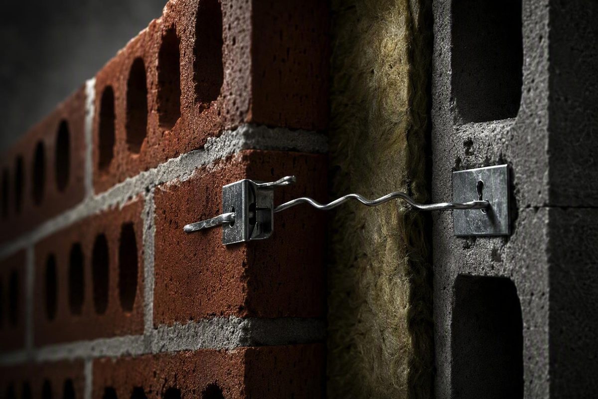
Masonry ties are small components in a structural and enclosure system that is anything but simple. A tie must transfer lateral load from the veneer or outer wythe to a qualified backup while accommodating the movement intended by the wall design. Its performance depends on every link in the path: veneer, mortar embedment, connector, anchor base, fastener, structural backup, and the surrounding air, water, and insulation layers.
Selecting masonry ties by familiar shape, generic spacing, or catalog category is therefore unreliable. The correct system depends on the wall type, backup material, actual unsupported tie span, cavity and insulation geometry, wind and seismic demand, movement, exposure, attachment method, adopted code, and exact product documentation.
This guide explains how to select, specify, detail, review, and inspect the connection as a complete load path. It is general technical guidance, not a substitute for approved construction documents, current manufacturer instructions, project-specific engineering, or review by the authority having jurisdiction. Code and standard editions referenced by secondary sources may not be the editions adopted for a particular project.
What masonry ties do—and how ties differ from anchors and fasteners
The terminology matters because similar-looking pieces of metal can perform materially different jobs:
- A wall tie connects one masonry wythe to an adjacent masonry wythe.
- A masonry anchor connects masonry to a structural support or frame.
- A fastener connects an appliance or component to masonry.
These classifications follow CMHA’s technical guidance on masonry anchors and ties. In everyday construction language, however, “brick tie,” “veneer tie,” and “veneer anchor” are often used loosely. Drawings and specifications should remove that ambiguity.
For anchored veneer, the tie or anchor laterally supports the masonry and transfers out-of-plane wind and seismic forces back to the structure. The veneer remains a distinct wall component; the connector is not a reason to assign it structural functions beyond those established by the wall design.
A successful connector has apparently competing duties. It must be sufficiently stiff out of plane to transfer lateral load without excessive veneer deflection, yet it must permit the differential in-plane movement allowed by the design. Brick, concrete masonry, concrete, wood framing, and cold-formed steel do not necessarily expand, shrink, creep, or deflect together. A connector that is rigid in every direction can unintentionally couple materials that need to move differently.
Several related products should therefore not be treated as interchangeable:
- wall ties between masonry wythes;
- veneer anchors connecting masonry to a frame or structural backup;
- joint reinforcement used for reinforcement, crack control, or an approved tying function;
- column anchors connecting masonry at structural columns;
- restoration anchors installed through completed wall materials;
- rebar positioners that locate reinforcement;
- general-purpose masonry fasteners used to attach other components.
A useful selection model is:
Veneer or outer wythe → mortar embedment → tie or anchor → base or fastener → structural backup
Then add the governing demand: wind pressure, seismic effects, wall height, exposure, geometry, and movement. Failure can occur at any link through fastener withdrawal, substrate failure, connector yielding, compression buckling, excessive free play, mortar pullout, corrosion, or poor installation.
The type, size, and location of connectors should be identified in the project drawings. “Provide masonry ties as required” leaves unresolved which backup receives the load, which fastener completes the connection, what unsupported span is allowed, and which spacing applies.
When masonry ties are required
The first distinction is between anchored and adhered veneer.
Anchored masonry veneer is mechanically connected to its backup with ties or anchors. Vertically installed adhered veneer relies on an approved mortar, adhesive, or proprietary bonding system rather than conventional wall ties. Some thin-unit systems use mechanically attached panels, rails, or tracks, so unit thickness alone does not classify the assembly; the attachment method shown in the evaluated system does. This distinction is summarized in Masonry Magazine’s discussion of anchored and adhered brick veneer.
Wall ties also occur in several multiwythe configurations:
- Composite walls, where the wythes are designed to act together;
- Noncomposite walls, where the wythes are connected laterally but permitted more independent in-plane behavior;
- Veneer walls, where the outer masonry is laterally supported by structural backing.
The connector configuration and movement assumptions differ among these systems. A connection appropriate for intended composite action may be unsuitable where the wythes must move independently.
A trade-publication summary of the 2011 masonry code states that masonry walls with two or more wythes separated by an air space require wall ties and describes different configurations for composite and noncomposite walls. Those provisions are useful for understanding the system, but their numerical requirements are edition-specific and should not be applied without checking the currently adopted code and amendments.
Construction sequence creates another important divide:
- New-construction anchors attach to the backup and are embedded as the veneer is laid.
- Restoration anchors are drilled or otherwise installed through completed masonry and existing wall materials.
A new-construction tie is not automatically a suitable repair anchor. Restoration work requires a system designed and documented for those conditions.
Use this short decision sequence:
- Classify the outer material. Is it mechanically anchored, conventionally adhered, or part of a proprietary panel system?
- Identify the backup and load path. Determine which structural material ultimately resists the lateral load.
- Choose the compliance pathway. Decide whether the attachment falls within current prescriptive provisions, a tested and evaluated proprietary system, or project-specific engineering.
Do not substitute a new-construction tie for a restoration anchor, and do not treat adhered and anchored veneer as equivalent simply because both use brick-faced units.
Types of masonry ties and anchors
Connector names describe broad families, not guaranteed performance. Two products with similar shapes can have different materials, dimensions, adjustment ranges, fasteners, substrate approvals, and tested capacities.
Corrugated sheet-metal ties are commonly associated with brick veneer over wood framing. They are a limited, assembly-dependent option generally associated with narrow cavities and coordinated attachment to framing. They should not be extended across a wider cavity merely because the strap can physically reach.
Fixed wire ties and anchors include rectangular, triangular, Z-shaped, and other wire configurations. Some connect one masonry wythe to another; others attach veneer directly to a backup. A directly attached fixed tie must align with the veneer bed joint, making coursing and backup layout critical. Its attachment also needs an approved fastener or embedment into the actual substrate.
Adjustable anchors are generally two-piece systems. A base connects to the backup, while a wire tie, pintle, or mating component engages the base and enters the veneer bed joint. The arrangement can accommodate coursing misalignment, construction tolerances, sequencing, and permitted differential movement. Eye-and-pintle, dovetail, and slotted systems are among the adjustable families described in Construction Specifier’s masonry-veneer guidance.
Adjustability does not prove capacity. The designer still needs to verify:
- component engagement;
- permitted vertical offset;
- free play between parts;
- unsupported wire or pintle span;
- out-of-plane stiffness;
- fastener and base capacity;
- suitability for the backup;
- evaluated cavity range and loading direction.
Pintle-and-eye systems use a projecting pintle engaged with an eye or loop. Slotted systems permit movement or adjustment along the slot’s axis. These families can appear forgiving in the field, but excessive offset, partial engagement, or excessive clearance can depart from the tested or designed condition.
Dovetail systems use an anchor compatible with a dovetail slot. The slot may be cast into a concrete wall or column, avoiding a post-installed fastener at that connection. Movement and adjustment are constrained by the slot geometry. Wire or sheet-metal components may be paired with compatible slots, but compatibility must be documented rather than inferred from shape.
Sheet-metal anchors are not necessarily the same as light corrugated straps. They may be thicker, factory-bent components with a defined base, leg, or slot connection. A technical comparison of sheet-metal, wire, adjustable, and dovetail anchors identifies significant differences in geometry, joint alignment, and backup attachment.
Joint reinforcement may form part of a wythe-tying arrangement where the wall design and applicable requirements permit it. It is not a default substitute for a dedicated veneer anchor. Ladder-type reinforcement may be preferable where differential movement is expected or vertical reinforcement is present. Truss-type reinforcement crosses the joint diagonally and can restrain differential in-plane movement in a noncomposite wall.
Manufacturer catalogs illustrate the breadth of the market: wall ties, veneer anchors, column anchors, pintle ties, web ties, dovetail anchors, corrugated straps, adjustable assemblies, and rebar positioners can appear in related categories. That variety is useful during product research, but a catalog label establishes availability—not suitability, capacity, or compliance.
Selection matrix: match the tie to the backup and wall geometry
Start with the structural backup, not the product name.
| Backup material | Commonly considered connector families | Primary coordination issues | Documents to verify |
|---|---|---|---|
| Wood studs | Corrugated ties for qualifying narrow-cavity assemblies; screw-attached adjustable bases; tested proprietary veneer anchors | Structural stud location, sheathing thickness, fastener penetration, stud withdrawal resistance, cavity span, insulation, barrier sealing, coursing | Adopted residential or building code, structural drawings, evaluation report, test data, fastener schedule, installation instructions |
| Cold-formed steel studs | Adjustable veneer anchors, screw-attached bases, evaluated proprietary systems | Stud thickness and capacity, deflection, screw type, pullout and pullover, sheathing and insulation thickness, vertical adjustment, barrier penetration | Structural stud design, current product report, tested substrate conditions, fastener requirements, wall details |
| CMU or masonry | Wythe-to-wythe wire ties, approved joint-reinforcement assemblies, adjustable veneer anchors, embedded or post-attached bases | Structural wythe versus veneer connection, hollow or grouted cells, anchor location, bed-joint alignment, movement | Masonry design, grout drawings, connector data, embedment details, adopted masonry standard |
| Concrete | Cast-in dovetail slots, cast-in channels, post-attached bases, sheet-metal or adjustable systems approved for concrete | Cast-in tolerances, edge distance, post-installed anchor approval, slot compatibility, sequencing, movement | Structural drawings, concrete-anchor approval, evaluation or test report, installation instructions |
| Structural steel | Adjustable ties, channels, welded or bolted bases, column-anchor systems | Attachment method, weld access, coatings, fireproofing, movement and deflection, framing orientation, enclosure continuity | Structural connection detail, welding or bolting requirements, coating-repair procedure, product data |
| Masonry wythe | Fixed wire ties, adjustable ties, approved joint-reinforcement assemblies | Composite or noncomposite behavior, cavity, bed-joint alignment, differential movement, hollow-unit engagement | Wall design, masonry specification, reinforcement drawings, tie schedule |
For wood studs, corrugated ties may remain candidates only where adopted provisions or an exact product evaluation cover the airspace, loading, fastener, and framing arrangement. Once the cavity, insulation, or coursing tolerance exceeds those conditions, move to a specifically tested adjustable system or an engineered alternative.
For steel studs, the anchor base and screw are part of the structural load path. A strong tie connected by an unsuitable screw to a light or highly flexible stud does not create a strong connection. Verify stud thickness and capacity, framing deflection, screw withdrawal and pullover behavior, sheathing layers, and whether the evaluated assembly matches the project.
For CMU or masonry backup, first decide whether the connector ties two structural wythes or anchors nonstructural veneer to the backup. Those are different design problems. In hollow masonry, the applicable detail may require a unit tie to extend across the unit or a concentrated anchor to engage a filled core. CMHA guidance specifically distinguishes unit ties in hollow masonry from anchors carrying larger concentrated loads.
For concrete, cast-in slots can simplify attachment but require early coordination and accurate placement. Do not assume that a base sold for masonry is also approved for concrete.
For structural steel, channels and column-anchor systems can accommodate geometry and construction sequence, but the attachment needs project-specific treatment of welding or bolting, steel coatings, fireproofing, movement, and enclosure continuity. The connection should be coordinated with the frame deflection and movement assumptions established by the wall design.
Cavity width is not the same as unsupported tie span
Record at least three dimensions separately:
- clear drainage cavity or airspace;
- insulation and other stand-off thickness;
- unsupported length of the wire, pintle, strap, or projecting component.
A nominal “four-inch cavity wall” does not reveal whether four inches refers to the clear airspace, face-to-face separation, insulation thickness, or total assembly depth.
As the load path lengthens, connector stiffness generally decreases and concerns about compression buckling, tension, pullout, and load distribution become more significant. CMHA’s wide-cavity discussion notes that the wire span—particularly a pintle’s unsupported span—can be more critical than nominal cavity width. A wider assembly may require a more robust connector, reduced spacing, applicable proprietary testing, or engineered analysis rather than merely a longer version of the original tie.
Decision tree
Use this sequence before naming a product:
- Define the wall and backup. Is it anchored veneer, a multiwythe wall, or another system? Is the backup wood, steel studs, CMU, concrete, masonry, or structural steel?
- Measure the geometry. Record clear airspace, insulation, total cavity, base projection, and unsupported wire or pintle span.
- Establish demand. Determine wind pressure, seismic condition, wall height, exposure, tributary area, and local discontinuities.
- Resolve movement and tolerances. Consider backup deflection, differential material movement, coursing alignment, construction sequence, and adjustment range.
- Select corrosion protection. Base it on exposure, humidity, adjacent metals, specification, and governing requirements.
- Verify the base and fastener. Check substrate, diameter, length, embedment or penetration, edge distance, head configuration, and coating.
- Choose the compliance path. Use a current prescriptive provision, a tested and evaluated proprietary system, or project-specific engineered design.
Capacity, spacing, embedment, and code limits
Masonry-tie compliance generally follows one of three paths:
- Prescriptive: The complete assembly falls within the limitations of the locally adopted code or referenced standard.
- Proprietary tested or evaluated: The exact system is supported by applicable testing or an evaluation report covering its components and conditions.
- Engineered: A qualified design professional establishes the loads, resistance, stiffness, spacing, and details for the project.
Do not mix these paths casually. Prescriptive spacing taken from one assembly cannot validate a different proprietary tie across a longer span. An evaluated product likewise remains subject to every limitation stated in its report.
What controls tie spacing
Required tie capacity and spacing can depend on:
- design wind pressure and seismic effects;
- veneer height, unit geometry, and tributary area;
- backup material, strength, stiffness, and deflection;
- tie strength and out-of-plane stiffness;
- base and fastener resistance;
- unsupported connector span;
- mortar-joint geometry and embedment;
- openings, edges, corners, parapets, shelf angles, and movement joints;
- governing code, standard, amendments, and product limitations.
A standard’s maximum spacing is a geometric ceiling, not proof that the resulting number of ties can resist the calculated loads. The Canada Masonry Design Centre’s veneer-tie guidance expressly warns against specifying maximum permitted spacing without analysis demonstrating sufficient resistance.
Common baseline numbers—and their limits
Published guidance reports approximately one tie per 2 to 2⅔ square feet for certain prescriptive anchored-brick-veneer configurations. That is a recurring range, not a universal tie-count formula; density changes with the applicable provision, tie type, backup, cavity, testing, and design demand. The same guidance describes additional ties near discontinuities and closer spacing in higher wind or seismic conditions.
Approximately 1½ inches of embedment into the veneer and ⅝ inch of mortar or grout cover to the exterior face also recur as baseline dimensions in industry guidance. A 2011-code summary reports those values and states that the mortar bed joint should be at least twice as thick as the embedded anchor, but all of these dimensions remain edition- and assembly-dependent and require verification against current project requirements (Masonry Magazine).
The connector must fit within the horizontal mortar bed while maintaining the specified cover. Tie diameter, joint thickness, masonry-unit tolerances, and field placement must therefore be coordinated. A larger-diameter wire is not automatically better if it leaves inadequate mortar above or below the connector. Unit selection and modular brick dimensions and coursing can also affect bed-joint alignment and coordination.
Additional ties are commonly required near openings, unsupported panel edges, and discontinuities. The same older 2011-code summary described additional anchors within 12 inches of certain openings and prescribed perimeter spacing for the configurations it addressed. Treat those figures as historical, edition-specific examples—not current universal rules.
Wide cavities
Older U.S. technical guidance described 4½ inches as a threshold beyond which wall-tie analysis was required. Other sources describe larger limits for particular backups or tested systems. These statements can refer to different code editions, backup materials, tie types, and compliance pathways; they should not be combined into a single universal cavity limit.
For a wider wall, analysis or applicable evaluation should address:
- tension under suction or load reversal;
- compression and connector buckling;
- fastener withdrawal, pullout, or pullover;
- base-plate and substrate behavior;
- mortar pullout and veneer breakout;
- out-of-plane stiffness and deformation;
- free play in adjustable components;
- distribution of load among ties.
The unsupported wire or pintle span may be more critical than nominal cavity width. A system with a substantial base projecting through insulation may have a shorter free wire span than another system within the same face-to-face cavity.
U.S. compliance roadmap
For a U.S. project:
- Identify the locally adopted IBC or IRC, including state and local amendments.
- Identify the referenced edition of TMS 402/602.
- Establish loading under the applicable ASCE 7 edition and project criteria.
- Classify the wall and confirm whether prescriptive provisions apply.
- Review current evaluation reports, testing, and installation instructions for proprietary systems.
- Obtain project-specific engineering where the assembly falls outside prescriptive or evaluated limits.
TMS 402/602 is identified as a U.S. source for masonry-anchor requirements and ASCE 7 as a loading source in technical guidance on new-construction masonry anchors. The governing documents are the editions adopted for the project—not the edition cited by a secondary article or an undated product page.
Canadian compliance roadmap
For a Canadian project:
- Identify the governing provincial or territorial building code.
- Confirm the referenced editions of CSA A370 for masonry connectors, CSA A371 for masonry construction, and CSA S304 for structural masonry design.
- Determine whether the applicable empirical-design pathway is available.
- If it is not, design the ties using the applicable structural provisions and factored loads and resistances.
- Coordinate the exact connector, backing, spacing, and construction tolerances.
The empirical pathway discussed by the Canada Masonry Design Centre has strict eligibility conditions. Under the cited CSA S304-14 framework, Annex F does not cover veneer backed by wood or steel studs; the guidance directs those cases to structural design under Clause 9. It also identifies restrictions involving concrete or masonry backing and veneer geometry. Current editions and local adoption must be verified.
Stop and escalate
Do not rely on a generic schedule when the project includes:
- cavities outside the applicable prescriptive or evaluated range;
- long unsupported wire or pintle spans;
- high wind or significant seismic demand;
- high-rise façades or flexible backups;
- unusually large, thin, or nonstandard veneer units;
- nonstandard backup materials;
- heavy stone or atypical veneer geometry;
- large stand-offs, clips, rails, or rain-screen framing;
- restoration of an existing wall with uncertain conditions;
- any substitution that changes the tie, base, fastener, substrate, or cavity.
Corrosion protection and enclosure coordination
Exterior ties and anchors are exposed to moisture entering the cavity and to the alkaline environment of mortar. Corrosion protection should be selected for the connector material, fabrication, exposure, humidity, service environment, governing requirements, and project specification.
Specified galvanizing or another permitted protective system is common for carbon-steel connectors. “Galvanized” alone is incomplete: the coating method, coating requirement, treatment after fabrication, and protection of cut or welded areas can matter. Different galvanized finishes should not be assumed equivalent.
Technical guidance also addresses Type 304 and Type 316 stainless steel connectors. Stainless steel may warrant consideration in wet, coastal, industrial, or otherwise corrosive environments, but neither grade is a universal answer. Exposure, specification, fabrication, cleaning chemicals, and compatibility with adjoining metals remain relevant. Construction Specifier discusses hot-dip galvanized exterior anchors and stainless-steel ties for unusually wet or corrosive conditions, while still requiring project-specific selection.
Add galvanic compatibility to the submittal and detailing checklist. Review ties, anchor bases, screws, flashing, shelf angles, channels, rails, and structural attachments as an interacting set. The available guidance does not provide a complete compatibility table, so project-specific material advice may be necessary.
Insulation, barriers, and thermal bridges
Continuous insulation and rain-screen stand-offs affect more than anchor length. They can:
- increase the connector load path and unsupported span;
- move the base farther from the veneer;
- create point thermal bridges;
- complicate drainage and flashing;
- introduce repeated penetrations through air- and water-control layers;
- make installation and inspection more difficult.
Anchor-base and fastener penetrations through air- or water-resistive barriers should be coordinated with a sealing detail compatible with the barrier and anchor system. Structural attachment cannot be reviewed independently from airtightness and drainage. A structurally adequate screw can still create an enclosure defect if the penetration is left unsealed or configured to direct water toward the backup.
Manufacturers may publish thermal simulations for proprietary anchors, but those results are specific to the modeled product, spacing, materials, and boundary conditions. They do not establish a universal whole-wall energy benefit.
Installation details and common field failures
Inspect the complete connection, not only the visible end of the tie:
Structural backup → approved fastener or base → tie orientation and engagement → unsupported span → bed-joint embedment and cover → veneer
A properly selected anchor may not perform as intended if any stage is improvised.
Attachment to the backup
Framed-wall ties should attach to structural studs or another qualified backup—not merely to plywood or OSB sheathing unless a specifically evaluated or engineered design establishes that load path. Sheathing can conceal missed studs, so layout and inspection are important before the veneer closes the wall. Field guidance on recurring brick-tie defects similarly emphasizes attachment to structural framing rather than sheathing alone (Pro Builder).
Use the exact fastener specified or approved for the tie, substrate, loading, and evaluation conditions. Verify diameter, length, head geometry, material, coating, framing penetration, and installation method. A residential nail recommendation from a field article is not a universal specification for screws, steel studs, masonry, concrete, or proprietary systems.
For hollow masonry backup, check the applicable wall detail. CMHA guidance states that unit ties in hollow masonry extend across the hollow units and recommends engagement with filled cores for anchors carrying relatively large loads. Coordinate anchor locations with grout and reinforcement drawings before the intended substrate becomes inaccessible.
Tie orientation and span
Corrugated ties normally have an intended orientation. Reversing one can produce spring-like behavior under lateral load and may create an unfavorable path for water. Follow the approved detail and product instructions rather than relying on visual preference.
Do not flatten, elongate, or “make fit” a narrow-cavity corrugated tie across a wider gap. Longer projection changes stiffness and buckling behavior. Use a system tested, evaluated, or designed for the actual airspace, insulation, and unsupported span.
Bed-joint placement
Veneer ties normally belong in horizontal bed joints rather than vertical head joints. Technical guidance on new-construction anchors identifies horizontal bed joints as the normal location and notes that adjustable anchors can accommodate differential movement between the veneer and backup.
During construction, verify:
- alignment with the bed joint;
- required embedment into the veneer;
- exterior mortar cover;
- mortar above and below the connector;
- full encapsulation where required;
- correct orientation;
- adequate engagement of adjustable components;
- permitted vertical offset and free play.
Field modification can change stiffness, coating integrity, engagement, and tested behavior.
Openings and discontinuities
Inspect supplemental ties around windows, doors, wall ends, movement joints, shelf angles, parapets, and unsupported edges before concealment. These are locations where regular spacing grids are interrupted and local support becomes more important.
Also inspect the enclosure work. Confirm that penetrations are sealed, flashing remains continuous, drainage paths are open, and ties do not slope or deform in a way that encourages water to move toward the backup.
Three-stage field checklist
Before installation
- Review approved shop drawings, exact product data, evaluation reports, and engineering.
- Confirm backup type, framing layout, grout locations, cavity geometry, and tie schedule.
- Verify fasteners, corrosion protection, barrier-sealing materials, and compatibility.
- Build and approve a mockup where required.
- Resolve coursing and anchor-base elevations before work begins.
During installation
- Confirm attachment to the intended structural substrate.
- Check tie spacing and supplemental ties at discontinuities.
- Verify exact fasteners, penetration, and edge conditions.
- Check orientation, free span, adjustment, and component engagement.
- Confirm bed-joint embedment, cover, and mortar encapsulation.
- Inspect barrier sealing and maintain drainage.
- Photograph representative and unusual conditions before concealment.
At closeout
- Compile inspection reports and photographs.
- Record approved substitutions and product-report revisions.
- Document nonconforming work and its disposition.
- Confirm that repairs were reinspected before concealment.
- Retain engineering letters, test evidence, and field-clarification sketches with project records.
How to review a masonry-tie submittal
A useful submittal identifies the complete system. “Adjustable masonry ties by an approved manufacturer” is not enough.
Require:
- manufacturer and product family;
- exact model or catalog number;
- tie and base dimensions;
- wire diameter or sheet thickness;
- material and finish;
- adjustment range and required engagement;
- intended backup and veneer;
- exact fastener;
- allowable cavity and unsupported span;
- installation orientation;
- required embedment and mortar cover;
- spacing and edge details;
- supporting reports and instructions.
Review performance in context
Declared capacity should correspond to the actual tie span, loading direction, veneer, mortar engagement, base, fastener, and substrate. Ask what failure mode controls. A value based on wire strength alone may not represent fastener withdrawal, steel-stud pullover, mortar pullout, adjustable-component deformation, or concrete-anchor behavior.
Review current:
- evaluation reports;
- test reports;
- code references and report revisions;
- installation instructions;
- sealed engineering letters where applicable;
- shop drawings and project details;
- specification sections.
An evaluation report for a product series may not cover every model. Confirm the exact model, fastener, substrate, framing thickness, cavity range, wind pressure, and seismic condition. Check exclusions and installation notes as carefully as headline values.
Fastener review should include diameter, length, material, corrosion protection, head or washer configuration, framing penetration, edge distance, substrate strength, and installation tooling. “Fasteners by others” leaves a critical load-path component undefined.
Review geometry and enclosure integration
Confirm:
- clear airspace, insulation thickness, and total cavity;
- unsupported wire or pintle span;
- anchor-base projection;
- veneer embedment and exterior cover;
- mortar-joint thickness;
- permitted offset, free play, and adjustment;
- tie density and maximum horizontal and vertical spacing;
- added ties near openings and unsupported edges;
- movement-joint, shelf-angle, and sequencing details;
- flashing and drainage continuity;
- barrier sealing at penetrations;
- compatibility with insulation clips, rails, girts, and accessories.
Manufacturer websites commonly provide submittal sheets, specifications, CAD details, and test-data links. Those resources are useful only after the underlying documents are reviewed. A category page showing products for concrete, masonry, wood studs, steel studs, and structural steel demonstrates market variety—not approval of each product for the proposed assembly.
One-page approval checklist
An approval record should answer all of these:
- [ ] Is the exact model identified?
- [ ] Does its intended use match the wall and backup?
- [ ] Are material and corrosion protection specified?
- [ ] Is the exact fastener identified and approved for the substrate?
- [ ] Does the evidence cover the actual cavity and unsupported span?
- [ ] Are design loads and relevant failure modes addressed?
- [ ] Are spacing, embedment, cover, and opening details shown?
- [ ] Are adjustment limits and component engagement clear?
- [ ] Are evaluation and test documents current and model-specific?
- [ ] Are insulation, flashing, drainage, barriers, and movement coordinated?
- [ ] Are installation and inspection requirements included?
- [ ] Are substitutions reviewed as complete systems rather than isolated parts?
Return or reject the submittal when it contains obsolete code references, missing exact-model evidence, unverified substitutions, unspecified fasteners, unsupported cavity extensions, incomplete corrosion information, or installation details that conflict with the wall assembly.
Frequently asked questions
How many masonry ties are needed per square foot?
For certain prescriptive anchored-brick-veneer configurations, published guidance commonly reports approximately one tie per 2 to 2⅔ square feet of wall area. That range is not universal. Required density can change with the adopted code, tie type, backup, cavity span, fastener, wind and seismic demand, and proprietary testing.
Also check maximum horizontal and vertical spacing and supplemental ties around openings and unsupported edges. The correct quantity is the controlling requirement produced by structural capacity, maximum-spacing rules, and local detailing conditions—not a single square-foot ratio.
Can corrugated brick ties be used across a 2-inch or wider cavity?
Not by assumption. Conventional corrugated ties commonly correspond to wood-framed, narrow-cavity conditions. Some tested products provide specific configurations for wider airspaces, while other products are expressly designed for spans in the two- to three-inch range.
As one documented manufacturer example—not a general product recommendation—Simpson Strong-Tie publishes different airspace and spacing conditions for conventional and wider-airspace models on its BT-series technical page. Those conditions include model-, fastener-, load-, wind-, and seismic-related limitations that must be checked in the current product documentation.
Verify what the stated dimension means: clear airspace, total cavity, or unsupported tie span. If the proposed assembly lies outside current prescriptive or evaluated limits, use a project-specific engineered solution.
How far should a masonry tie embed into brick veneer?
Approximately 1½ inches of embedment recurs as a baseline in industry guidance, together with approximately ⅝ inch of mortar or grout cover to the exterior face. These are not universal dimensions for every tie, unit, mortar joint, or code edition.
The tie should be located in the horizontal bed joint, properly encapsulated, and coordinated with unit width and joint thickness. Follow the adopted code, approved system instructions, and project documents where they differ.
Do masonry ties attach to sheathing or to the structural studs?
In framed construction, ties generally should complete the load path to structural studs or another qualified backup rather than rely on plywood or OSB sheathing alone. Sheathing may lie between the anchor base and the stud, but the specified fastener must still achieve the required structural engagement.
An exception requires explicit support from an evaluated or engineered assembly that recognizes the actual sheathing, fastener, edge conditions, and loads. Do not infer structural adequacy merely because a screw can be driven into the sheathing.
Do adhered thin-brick walls need masonry ties?
Conventionally adhered thin brick installed vertically generally relies on an approved mortar, adhesive, or proprietary bond system rather than conventional masonry ties. That makes it a different wall system from anchored brick veneer.
Some thin-brick assemblies use mechanically attached panels, rails, or hybrid systems. Follow the evaluated assembly and project details rather than deciding from brick thickness alone.
Conclusion
The final selection sequence is straightforward even when the engineering is not:
- Define the wall and complete load path.
- Identify the structural backup.
- Measure the actual cavity, insulation, base projection, and unsupported tie span.
- Establish wind and seismic demands.
- Select the corrosion-protection and movement strategy.
- Verify the exact connector, base, fastener, spacing, embedment, and enclosure details against current project documents and locally adopted requirements.
A familiar tie shape or generic spacing rule is not a substitute for a coordinated, documented connection.