
How to Give a Brick Wall Enough Room to Move
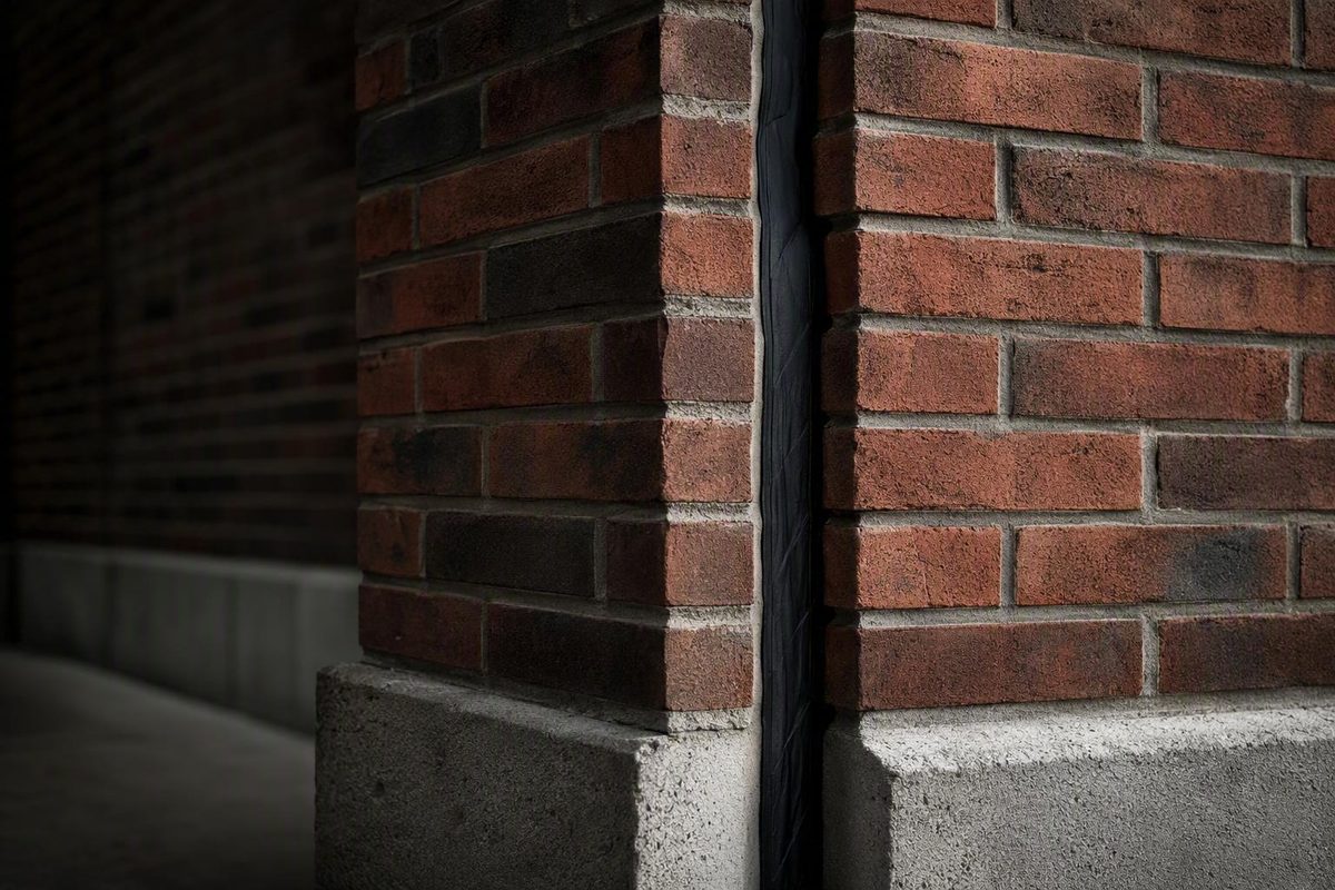
Brick looks rigid, but a brick wall is not dimensionally fixed. Temperature and moisture conditions change its dimensions, clay brick develops long-term moisture expansion, and the structure supporting it can deflect, deform, or settle. When adjoining materials or separate wall sections move by different amounts, even small dimensional changes can generate significant stress.
Expansion joints in brickwork provide planned locations for that movement. Effective movement control involves more than inserting sealant lines at regular intervals. The designer must identify the wall assembly, governing jurisdiction, expected movement, geometry, supports, openings, exposure, and restraints. Each joint must then be located, sized, detailed, constructed, and maintained as part of the complete wall system.
Why brick walls move—and what happens when they cannot
Brickwork movement has several components. Separating them conceptually helps explain why a wall needs capacity for both recurring and long-term change.
Reversible movement occurs as environmental conditions vary:
- Brickwork expands as its temperature rises and contracts as it cools.
- Changes in moisture content can produce additional reversible movement.
- Different elevations—or different portions of one elevation—may experience different temperatures and wetting conditions.
- Dark or strongly sunlit surfaces may heat differently from shaded walls.
- Parapets and freestanding walls can be exposed on more surfaces than protected wall panels.
The wall consequently moves back and forth through daily and seasonal cycles. The direction and magnitude at any moment depend on temperature, moisture, exposure, panel length, and restraint.
Clay brick also undergoes cumulative moisture expansion after manufacture. Unlike ordinary thermal cycling, this behavior is generally treated as net, long-term expansion. UK building-control guidance distinguishes reversible temperature and moisture movement from long-term material behavior, including the expansion of clay brickwork over time (LABC guidance on brickwork movement joints).
Movement within the brick is only part of the problem. Differential movement may also result from:
- Deflection of structural frames, floors, lintels, and shelf angles
- Elastic or long-term deformation under load
- Settlement or rotation of foundations and supports
- Changes from one backup material to another
- Different support conditions along an elevation
- Wind and other lateral loads
- Adjoining cladding materials with different movement characteristics
- Uneven solar, rain, and temperature exposure
- Frames, penetrations, or fixings that restrain the masonry locally
Consider a long brick panel bounded by rigid returns. As the panel expands, its ends push against those boundaries. If neither the masonry nor its interfaces can move, compressive stress accumulates. Openings, offsets, supports, and other geometric interruptions can concentrate that stress.
Restraint can contribute to cracked mortar or brick, displaced units, failed perimeter seals, water entry, and reduced envelope performance. These outcomes are possible rather than inevitable. Their occurrence and severity depend on the wall’s geometry, stiffness, condition, support, anchorage, exposure, and ability to relieve stress elsewhere.
A brick expansion joint is a planned, continuous, unobstructed separation that allows adjoining sections of brickwork to move relative to each other. Flexible components—often including compressible filler, a backer rod or bond breaker, and elastomeric sealant—accommodate movement while helping the exterior resist water penetration.
The word continuous matters. A neat sealant bead at the face does not create a functional joint if mortar, debris, shims, insulation, anchors, or services rigidly connect the masonry behind it. The joint is not merely a finish item: it must be coordinated with wall ties, flashing, drainage, air and water control layers, structural supports, openings, and adjoining construction.
Expansion joint, control joint, or building joint?
Movement-joint terminology should follow both the material and the function of the separation.
For clay-brick masonry, expansion joint is the usual term because the brickwork experiences net expansion. For concrete masonry units, control joint is generally used because concrete masonry typically undergoes net shrinkage. A CMU control joint establishes a planned plane at which shrinkage-related cracking can occur in a controlled manner.
The Brick Industry Association uses the more specific term veneer expansion joint to distinguish a movement joint within brick veneer from a whole-building joint (BIA brickwork FAQ).
An isolation joint separates construction portions expected to behave differently—for example, walls with different heights, loads, bearing conditions, or support systems. The term describes the separating function; it does not establish one universal detail.
A building expansion joint, sometimes called a structural expansion joint, divides major portions of a building. It may continue through the structure, walls, floors, roof, and other assemblies. Purpose-designed systems must then restore the required environmental and performance functions across the opening.
A brick-veneer expansion joint has a more limited scope. It can exist only within the brick wythe and does not automatically need to pass through the backup wall, floors, foundation, and roof. Its purpose is to divide the veneer into panels that can accommodate brickwork movement.
| Joint type | Typical material or scope | Primary function |
|---|---|---|
| Clay-brick expansion joint | Clay-brick wythe; vertical or horizontal | Accommodates net brick expansion and reversible movement |
| CMU control joint | Concrete-masonry wythe | Provides a controlled plane for shrinkage movement and cracking |
| Isolation joint | Portions with different loads, heights, materials, or supports | Separates construction expected to behave differently |
| Building expansion joint | Multiple structural and envelope systems | Divides major building portions and accommodates building-scale movement |
Terminology comparison—not a construction detail.
In a modern cavity wall, an exterior clay-brick wythe and an interior CMU wythe may be connected with flexible ties while still moving differently. The brick expansion joints and CMU control joints may sometimes be located independently. That possibility does not remove the need to coordinate ties, membranes, flashing, insulation, structural stability, and differential movement across both wythes (IMI discussion of masonry movement-joint failures).
The drawing rule is straightforward: label what each joint does. A line marked only “movement joint,” without identifying its material, extent, orientation, and relationship to adjoining construction, leaves too much to field interpretation.
Spacing guidance: label the wall type and jurisdiction first
There is no single correct spacing for expansion joints in brickwork. A useful starting value for one wall type may be inappropriate for another.
Before selecting a spacing, establish:
- The governing jurisdiction and locally adopted code
- Whether the masonry is clay brick, concrete brick, calcium silicate, CMU, or another material
- Whether the wall is veneer, cavity construction, solid masonry, loadbearing masonry, or freestanding
- The brick properties and expected movement
- Wall height, length, thickness, and panel proportions
- The number, size, and pattern of openings
- Corner, return, offset, and intersection geometry
- The support system and anticipated deflection
- Changes in backup, support, material, or exposure
- Building height and environmental conditions
Only then should a published spacing figure enter the discussion.
| Source context | Wall condition | Published starting guidance | How to use it |
|---|---|---|---|
| UK LABC loadbearing-brickwork guidance | Straight clay-brick wall | Approximately 10–12 m | General source-specific guidance; confirm applicability to the actual assembly |
| North American BIA guidance | Clay-brick veneer without openings | Maximum approximately 25 ft on center | Initial maximum for the stated veneer condition |
| North American BIA guidance | Clay-brick veneer with multiple openings | Maximum approximately 20 ft on center | Evaluate placement around openings, including symmetrical layouts |
| UK LABC loadbearing-brickwork guidance | Freestanding wall | Half the spacing otherwise specified | Source-specific guidance requiring project verification |
| Summarized BIA guidance | Parapet run exceeding approximately 15 ft between vertical joints | Evaluate a wider joint or an additional intermediate joint | Applies to parapet conditions under the summarized guidance |
LABC presents the 10–12 m range for straight clay-brick walls and half-spacing for freestanding walls within guidance specifically framed around loadbearing brickwork. The same source also advises that joints near corners or returns should be within half the applicable maximum spacing without being so close that the return loses its buttressing function; it flags opening-defined panels with length-to-height ratios above 3:1, calls for cavity-wall ties within 225 mm of joint edges at no more than 300 mm vertically, and describes filler compressible to about 50% of its original thickness. These are source-specific parameters, not universal requirements, and their applicability to veneer or other assemblies must be confirmed through the relevant project guidance and design (LABC guidance on brickwork movement joints).
For North American clay-brick veneer, BIA’s published summary recommends maximum spacing of approximately 25 ft on center without openings and 20 ft on center where the brickwork has openings. Openings and other masonry features still affect placement, so those dimensions do not constitute a complete layout (BIA brickwork FAQ).
A secondary engineering summary of BIA material says that when a parapet has more than approximately 15 ft between vertical joints, the designer should evaluate wider joints or additional intermediate joints. It also reiterates that the 20-ft and 25-ft figures are maximum-spacing guidance for specified veneer conditions rather than universal prescriptions (Childress Engineering summary of BIA guidance).
The UK and North American values should not be merged, averaged, or treated as equivalent code provisions. They address different wall types, jurisdictions, customary details, and underlying assumptions.
Even within the correct scope, maximum spacing does not determine the complete layout. Shorter panels may be needed because of:
- A corner or short return
- Closely spaced or repeated openings
- A long, shallow masonry panel
- A change in structural support
- A tall or flexible frame
- A parapet or freestanding wall
- Strong solar or moisture exposure
- A change in material or wall function
- Unusual restraint
- Brick properties that increase anticipated movement
- Construction tolerances that reduce usable joint capacity
flowchart TD
    A[Identify jurisdiction and adopted code] --> B[Confirm masonry material]
    B --> C[Classify assembly: solid, loadbearing, veneer, cavity, or freestanding]
    C --> D[Map openings, corners, returns, offsets, and parapets]
    D --> E[Identify foundations, shelf angles, lintels, and changing supports]
    E --> F[Assess exposure, building height, frame movement, and restraint]
    F --> G[Locate stress points and movement transitions]
    G --> H[Calculate movement and joint capacity]
    H --> I[Verify remaining panel lengths against applicable guidance]
Spacing decision path—not for construction. Final dimensions require project analysis.
Before issuing any figure for construction, verify the following document families:
Source-verification checklist
- United Kingdom: applicable building regulations, local building-control requirements, current masonry standards, project engineering, and relevant technical guidance.
- North America: the locally adopted building code and amendments, the applicable TMS 402/602 edition, current BIA technical guidance, and project specifications.
- Every jurisdiction: structural and envelope drawings, selected sealant-system instructions, compatibility data, and tested systems required for fire, air, water, acoustic, or thermal performance.
The locally adopted code and project documents—not an isolated online spacing table—must govern the work.
Where joints belong on the elevation
Joint layout should begin with stress concentrations and movement transitions, not by dividing an elevation into visually equal segments. First identify where movement is likely to concentrate or adjoining portions may behave differently. Then add joints so the resulting panels remain within the applicable spacing and calculated movement capacity.
Recurring evaluation zones include:
- Long, uninterrupted wall runs
- Outside and inside corners
- Returns and short return walls
- Wall intersections
- Offsets and setbacks
- Changes in wall height or thickness
- Changes in brick or cladding material
- Changes in backup construction
- Changes in structural support
- Interfaces between foundation-supported and shelf-angle-supported veneer
- Large, repeated, or closely spaced openings
- Parapets
- Changes in exposure or wall function
Corners and returns require judgment. A corner restrains movement, but a joint placed too close to a return may weaken the return’s ability to buttress the wall. There is no universal corner offset. The designer must reconcile movement capacity with wall stability, bond, support, and the length of both adjoining elevations.
An outside corner does not automatically require a joint directly at the corner. Depending on the wall lengths and structural arrangement, the design may place a joint on one elevation, both elevations, or another nearby location. The resulting panels must still have adequate movement capacity.
Openings are interruptions and stress concentrations. They can create narrow piers between windows, short sections beside doors, and long, shallow panels above or below openings. Those portions may behave differently from an uninterrupted rectangular wall.
Jamb alignment may provide a visually coherent and constructible joint location, but a joint is not mandatory beside every opening. Evaluate:
- Large windows and doors
- Garage and loading-bay openings
- Repeated window bays
- Narrow piers
- Shallow spandrel panels
- Lintels and their bearings
- Frame perimeter clearance
- Symmetry of joint placement
- Conflicts with flashing, ties, or support
The source-specific LABC parameters tabulated in the spacing section flag elongated panels around doors and windows for closer evaluation. That guidance should not be converted into a universal threshold for every assembly.
Parapets require separate attention. A vertical joint should continue through the parapet brickwork rather than stopping below it. Copings, flashing, membranes, sealant, and drainage details must accommodate the same separation. Depending on the governing guidance and movement analysis, the parapet may need an additional joint or greater joint capacity than the wall below.
Support transitions can be equally important. Veneer bearing on a foundation ledge may move differently from veneer supported by a shelf angle or lintel. Where adjoining sections bear on different supports, a vertical movement or isolation joint may be appropriate. The decision must account for structural behavior, coursing, flashing, tie layout, and environmental-control continuity.
flowchart LR
    A[Long wall run] --> B[Corner or return zone]
    B --> C[Repeated openings and narrow piers]
    C --> D[Change in wall height or material]
    D --> E[Foundation-to-shelf-angle transition]
    E --> F[Parapet and exposed termination]
Elevation evaluation sequence. Each labelled condition is a review zone, not an automatic joint location or construction layout.
Vertical and horizontal joints must work with the wall assembly
Vertical expansion joints divide long elevations into panels and isolate portions likely to move differently. Horizontal expansion joints accommodate vertical differential movement, especially where veneer support changes.
In multistory veneer construction, a common horizontal-joint location is immediately beneath a shelf angle. The gap allows brickwork below to expand upward while the frame or supported veneer moves independently. If the opening is undersized, filled with mortar, or obstructed by temporary shims, it cannot provide its intended capacity.
Other possible horizontal-joint locations include:
- Changes in backup-wall material
- Interfaces between veneer materials with different movement behavior
- Selected conditions at the top of veneer
- Locations where support or frame movement changes
- Transitions requiring a slip plane or bond break
Masonry guidance specifically recommends removing temporary shelf-angle shims before completing the horizontal expansion joint (Nitterhouse guidance on preventing masonry cracks).
A shelf-angle detail must coordinate:
- Shelf-angle position and construction tolerance
- Expected frame and edge-beam deflection
- Veneer expansion below the angle
- Brick coursing and dimensional coordination
- Joint width and sealant geometry
- Flashing and end dams
- Cavity drainage and weeps
- Thermal-bridging provisions, where required
- Tie and anchor arrangement
- Air and water control layers behind the veneer
The visible horizontal sealant line is only the outer edge of this assembly.
Near vertical joints, ties must stabilize the brick panels without bridging the separation. Any source-specific tie dimensions—including those summarized in the spacing section—must be checked against the applicable local standard, cavity width, tie design, wind loading, and structural requirements.
Every interface crossing a movement zone warrants review:
- Window and door frames need dimensioned clearance.
- Flashing should drain without rigidly tying panels together.
- Insulation should not be packed so tightly that it obstructs movement.
- Anchors and fixings should not span the joint unless designed to permit movement.
- Pipes, conduits, and services should not lock the separation.
- Membranes may require folds or compatible flexible transitions.
- Slip planes must remain capable of slipping.
- Penetrations must preserve movement and weather resistance.
Those requirements are project-specific and must be met with compatible tested or otherwise approved systems. A standard exterior sealant detail does not establish those functions.
Anatomy of a functional, weather-sealed movement joint
A functional expansion joint requires clear separation through the brick wythe and a flexible exterior seal. The precise components vary, but the design intent should be unmistakable in section.
flowchart LR
    A[Brick panel A] --> B[Prepared mortar edge]
    B --> C[Elastomeric sealant]
    C --> D[Backer rod or bond breaker]
    D --> E[Clear continuous movement gap]
    E --> F[Compressible filler where specified]
    F --> G[Brick panel B]
    H[Nearby tie] --> I[Stabilizes panel without bridging gap]
    J[Flashing and drainage] --> K[Remain continuous and able to drain]
Conceptual joint anatomy—not for construction. Components, dimensions, and interfaces must be project-specific.
Joint width must account for:
- Reversible temperature and moisture movement
- Cumulative moisture expansion
- Distance between joints
- Brick and mortar behavior
- Structural and support movement
- Degree of restraint
- Construction tolerances
- Installation temperature
- The selected sealant system’s tested movement capacity
- Required minimum and maximum sealant dimensions
A nominal dimension copied from another project is not a design calculation. A generic 1/2-in joint, although found in some recommendations and details, is not universally correct. The same opening may provide adequate capacity in one short panel but be insufficient in a longer, more exposed, or more restrained panel.
Where specified, compressible filler occupies the separation without preventing joint closure. Material selection must account for compatibility, durability, moisture behavior, fire requirements, and suitability for the complete joint system. Source-specific examples or compressibility values should not be adopted without confirming that they apply to the project.
At the exposed face, a backer rod or bond breaker:
- Provides a nonbonding surface behind the sealant
- Controls sealant depth
- Discourages adhesion to three sides
- Supports tooling
- Helps create a movement-efficient sealant profile
A correctly selected bond breaker allows adhesion primarily to the two opposing joint faces.
Commercial recommendations sometimes prescribe a backer rod larger than the opening or fixed width-to-depth ratios. Those values should not be treated as universal. Final dimensions must follow the applicable project standard, specification, substrate conditions, calculated movement demand, and the selected sealant manufacturer’s current instructions.
Exterior joints and associated slip planes must remain flexible while resisting water penetration. Flashing and cavity drainage should assume that some water can pass the veneer; face sealant is not a substitute for a coordinated drainage system.
| Functional detail | Defective detail |
|---|---|
| Clear gap through the brick wythe | Mortar or brick debris bridges the opening |
| Sealant bonded to two prepared side faces | Sealant bonds to both sides and the back |
| Backer rod or bond breaker controls depth | Rigid backing prevents deformation |
| Calculated movement capacity | Nominal gap is too narrow for expected movement |
| Flexible membrane transition | Rigid penetration locks adjoining panels |
| Ties stabilize each panel without crossing the gap | Anchor or fixing spans the separation |
| Flashing drains around or through the detail | Flashing is folded or fastened so it restrains movement |
Correct-versus-incorrect movement-joint concepts—not construction details.
A joint can look correct at the face and still fail internally. Common hidden obstructions include mortar droppings, broken brick, retained shims, rigid filler, tightly packed insulation, screws, anchors, conduit, and services. Inspection should verify the full depth and continuity of the gap before it is closed.
Why joints fail—and what cracking can and cannot tell you
Movement joints fail when their location, capacity, continuity, or interfaces do not match the wall’s actual movement.
Typical failures include:
- Excessive spacing
- Placement away from stress concentrations
- Insufficient width
- A joint that stops below the top of the brickwork
- Mortar or brick debris bridging the gap
- Temporary shims left beneath shelf angles
- Rigid penetrations or fixings spanning the joint
- Poor sealant adhesion
- Three-sided sealant bonding
- Unsuitable sealant geometry
- Incompatible sealant or inadequate substrate preparation
- Missing clearance around frames
- Uncoordinated shelf angles, lintels, or supports
- Flashing and membrane details that restrict movement
A vertical crack beside a window may be consistent with restrained brick movement, particularly where an opening interrupts a long veneer panel. Its appearance alone does not prove that a missing expansion joint caused it.
| Observed symptom | Possible movement-joint issue | Other causes to investigate |
|---|---|---|
| Predominantly vertical crack | Restrained expansion, excessive panel length, poor joint location | Support movement, frame restraint, lintel behavior, impact |
| Stair-step crack | Differential movement or inadequate accommodation | Settlement, foundation rotation, support displacement |
| Open mortar joints | Panel movement or local loss of bond | Weathering, weak or incompatible mortar, poor repairs |
| Torn or detached sealant | Excess movement, poor adhesion, wrong geometry | Dirty substrate, incompatible materials, aging, installation defects |
| Water staining | Failed joint seal or interrupted flashing | Roof, coping, sill, cavity, or plumbing leakage |
| Loose brick | Movement-related displacement | Freeze-thaw deterioration, corrosion, failed bond, anchorage defects |
| Local displacement | Joint closure or support transition | Lintel movement, corroding steel, impact, foundation movement |
| Bowing or bulging | Accumulated compression or locked movement | Failed ties, corrosion, moisture damage, support instability |
| Recurring repaired crack | Active movement remains unresolved | Settlement, corrosion, deflection, incompatible hard repair |
A deflecting lintel or shelf angle can crack masonry near an opening. Missing or deteriorated anchors can contribute to outward movement.
Routine sealant deterioration must be distinguished from potentially unstable masonry. Loss of adhesion, tearing, or hardened sealant may call for joint restoration after the cause is confirmed. Loose, bowed, bulging, displaced, or outward-moving brickwork may indicate a support or anchorage problem and warrants prompt professional assessment rather than cosmetic repointing (overview of brick-joint distress).
Filling a working movement joint with hard mortar removes the flexibility for which the joint was created.
The evidence does not establish one fixed inspection interval. Inspection frequency should reflect exposure, joint-system durability, building importance, access, prior failures, and manufacturer recommendations. Inspect for:
- Adhesive failure at joint edges
- Cohesive tearing through sealant
- Hardening or embrittlement
- Excessive compression or extrusion
- Displacement at the joint
- Water entry or staining
- Mortar, debris, coatings, or repairs obstructing movement
- Deteriorated flashing, coping, or perimeter seals
- Loose units, corrosion, bowing, or bulging
Crack interpretation is a diagnostic task, not a pattern-matching exercise.
Design, documentation, construction, and retrofit checklist
Sources summarizing TMS 402/602 state that the building designer is responsible for indicating movement-joint types and locations on the project drawings (IMI brick construction guidance). The applicable edition, local adoption, amendments, and project requirements must still be verified.
Project-specific design should be completed or reviewed by the responsible designer or another competent structural professional. Architects, structural engineers, envelope consultants, masonry contractors, and sealant specialists may all contribute, but coordination responsibilities should not remain implicit.
Drawing and specification checklist
- [ ] Identify the brick and masonry type.
- [ ] Classify the wall as veneer, cavity wall, solid masonry, loadbearing masonry, or freestanding construction.
- [ ] State the applicable code, standards, technical guidance, and project criteria.
- [ ] Show vertical and horizontal joint orientations.
- [ ] Dimension every joint location on plans and elevations.
- [ ] State the designed joint width rather than relying on a graphic line.
- [ ] Document the movement calculation or design basis.
- [ ] Identify foundations, shelf angles, lintels, and other supports.
- [ ] Show clearance beneath shelf angles.
- [ ] Dimension clearances around window and door frames.
- [ ] Show tie and anchor arrangements near joint edges.
- [ ] Detail flashing, end dams, weeps, and drainage paths.
- [ ] Show slip planes and bond breaks.
- [ ] Detail parapet, coping, roof, and sill intersections.
- [ ] Locate penetrations and show flexible transitions.
- [ ] Coordinate insulation and air and water control layers.
- [ ] Specify filler, backer rod or bond breaker, primer where required, sealant, preparation, and tooling.
- [ ] State applicable manufacturer instructions and compatibility requirements.
- [ ] Identify required fire, acoustic, thermal, or air-barrier performance.
Installation checklist
- [ ] Confirm joint locations against approved drawings before laying brick.
- [ ] Verify that the gap is continuous through the brick wythe.
- [ ] Keep mortar from entering the opening.
- [ ] Remove mortar droppings and brick debris.
- [ ] Remove temporary shelf-angle shims where the design requires an open gap.
- [ ] Prevent anchors, services, insulation, and fixings from bridging the joint.
- [ ] Protect flashing and drainage components during construction.
- [ ] Confirm that substrates are sound, clean, dry, and prepared as specified.
- [ ] Install the specified compressible filler.
- [ ] Place backer rod without puncturing or damaging it.
- [ ] Maintain the specified sealant depth and profile.
- [ ] Tool sealant onto the intended bonding faces.
- [ ] Inspect concealed continuity before closure.
- [ ] Record deviations and obtain design direction rather than improvising rigid repairs.
New construction and retrofit require different starting points.
For new work, begin with movement analysis and coordinated drawings. Openings, coursing, support elevations, joint locations, and flashing can then be resolved before masonry installation.
For an existing wall, begin with diagnosis. Determine whether distress is associated with restrained expansion, settlement, support deflection, corrosion, failed anchorage, moisture, or another condition before repointing cracks or cutting a new joint.
Childress Engineering describes a case in which a joint was cut beside a window after the observed veneer crack was attributed to thermal movement and the absence of an expansion joint. That intervention was specific to the investigated wall and is not a standard repair for every crack beside an opening (Childress Engineering case report).
Before cutting a retrofit joint, locate or investigate:
- Wall ties and anchors
- Joint reinforcement
- Structural reinforcement
- Lintels and their bearings
- Shelf angles and connection points
- Flashing and end dams
- Air and water membranes
- Insulation
- Electrical, plumbing, and other services
- Structural supports
- Adjoining sealant and frame systems
Professional review is particularly important when cracking recurs, support arrangements are uncertain, or masonry is loose, displaced, bowed, bulging, or moving outward. Such conditions can involve support, corrosion, or anchorage defects rather than a routine sealant problem (brick-distress assessment guidance).
Educational guidance explains principles. The locally adopted code and amendments, applicable standards, project specifications, contract documents, and selected product instructions must be verified for the actual project. Engineering decisions belong to the responsible design professionals.
Frequently asked questions
How far apart should expansion joints be in brickwork?
There is no universal spacing. Begin by identifying the jurisdiction, masonry material, wall type, openings, supports, geometry, exposure, restraints, and building height.
Published values are scope-specific starting points. UK loadbearing-brickwork guidance and North American brick-veneer guidance address different conditions and must not be interchanged. Corners, returns, openings, parapets, unusual exposure, support transitions, and calculated movement may require closer spacing than the initial maximum.
How wide should a brick expansion joint be?
Width should be calculated from anticipated reversible and cumulative movement, panel length, material behavior, restraint, structural movement, construction tolerances, installation conditions, and the tested movement capacity of the selected sealant system.
A nominal width copied from another project is not a universal specification. Final dimensions must also account for filler, backer rod or bond breaker, sealant profile, minimum application dimensions, and manufacturer instructions. The joint must retain sufficient capacity throughout its movement range.
Should an expansion joint be placed beside every window, door, or corner?
No. Openings and corners are evaluation zones, not automatic joint locations.
A joint may align with a window or door jamb when that position addresses a stress concentration and can be coordinated with frames, lintels, flashing, and sealant. Repeated or large openings may justify closer spacing. At corners and returns, movement accommodation must be balanced against wall stability and buttressing.
The designer should address stress concentrations first and then verify that all remaining wall panels comply with the applicable spacing and movement criteria.
Can a brick expansion joint be filled with mortar?
No—not if it is intended to function as a movement joint. Hard mortar bridges the separation and restricts movement.
The joint normally requires a clear gap with flexible components such as compressible filler where specified, a backer rod or bond breaker, and elastomeric sealant. Mortar droppings concealed behind an otherwise neat sealant bead can also defeat the joint, so continuity must be inspected before sealing.
Can an expansion joint be added to an existing cracked brick wall?
Sometimes, but only after the cause of cracking and the concealed wall construction have been investigated.
Before cutting, locate ties, reinforcement, lintels, shelf angles, flashing, membranes, utilities, and structural supports. Obtain project-specific professional direction, particularly when cracking recurs or masonry is loose, displaced, bowed, bulging, or moving outward. Repointing or cutting solely from the visible crack pattern risks treating the symptom while leaving the underlying defect unresolved.
A successful expansion-joint layout begins with the wall’s actual material, assembly, geometry, supports, exposure, and governing jurisdiction—not a number copied from a table. It ends with a coordinated gap that installers can keep continuous, unobstructed, stable, drainable, and weather-resistant.