
Brick Veneer Needs Support, Ties and a Drainage Path
How anchored and adhered brick veneer differ, with practical guidance on cavities, flashing, weeps, ties, support and movement joints.
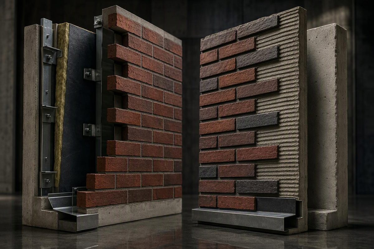
Brick veneer is a non-loadbearing brick facing, not a solid structural brick wall. In the common anchored system, the brick carries its own weight down to a foundation ledge or shelf angle, while metal ties transfer wind pressure and suction back to the structural wall. A cavity, water-resistive barrier, flashing and weeps manage rain that passes through the brickwork.
That distinction changes almost every drawing detail. Brick cannot simply be added to the outside of a framed wall as a finish layer: it needs bearing, lateral anchorage, drainage space and movement joints.
Anchored brick veneer versus thin brick
The term “brick veneer” is used for two physically different systems:
| System | How it is supported | Typical wall consequence |
|---|---|---|
| Anchored brick veneer | Full-depth brick bears on a footing, foundation ledge or shelf angle; ties connect it laterally to the backing | Requires a cavity, flashing, weeps, ties and substantial base support |
| Adhered thin brick veneer | Thin units are bonded to a prepared substrate or proprietary panel | Thinner and lighter, but dependent on substrate condition, bond, drainage detailing and movement joints |
Anchored veneer is typically a nominal 3- or 4-inch (76 or 102 mm) exterior wythe. Its resistance to out-of-plane load is not treated as independent wall capacity; anchors pass those loads to the backing, while the foundation normally supports the brick vertically. The Brick Industry Association’s wood-stud guide describes this load path and classifies the assembly as anchored masonry veneer (BIA Technical Note 28).
Thin brick is not the same assembly with narrower units. It is bonded to—and structurally dependent on—its backing. Installation may use a reinforced scratch coat, thin-set mortar over cement backer board, a modular panel or a prefabricated panel. Exterior stud-wall applications still require water-management components; BIA recommends two water-resistive-barrier layers or one layer with a drainage mat in its thin-brick guidance (BIA Technical Note 28C).
The anchored wall, layer by layer
A typical framed-wall section, outside to inside, is:
- brick and mortar joints;
- clear drainage cavity;
- corrosion-resistant masonry ties crossing the cavity;
- water-resistive barrier and flashings;
- exterior sheathing;
- structural studs, insulation and interior finish.
Continuous exterior insulation may sit between the water-resistive layer and drainage cavity. Its thickness changes the tie geometry and the total distance from backing to brick, so it cannot be added late without checking the specified anchor system.
The 2021 IRC table for residential masonry veneer illustrates the coordination involved. It specifies a nominal 1-inch airspace for corrugated ties and establishes different adjustable-tie requirements as the backing-to-veneer distance increases, up to 6⅝ inches in the listed prescriptive cases. It also requires corrosion-resistant ties to extend at least 1½ inches into the veneer, with at least ⅝ inch of mortar or grout cover to the outside face (2021 IRC Section R703.8.4). These figures are coordination references, not a substitute for the code edition and amendments adopted for a project.
On a drawing, dimension both the clear cavity and the full backing-to-veneer distance. A “1-inch cavity” note does not establish whether the selected tie can bridge thick exterior insulation.
Brick veneer is a drained wall
Mortar joints and brick are not assumed to stop every drop of wind-driven rain. Anchored veneer works as a drained assembly: water that reaches the back of the brick drops through the cavity, lands on flashing and exits through weeps. Building Science Corporation identifies the essential parts of this approach as cladding, a drainage gap, a drainage plane, flashing and drain openings (BSD-013).
For wood-stud construction, BIA recommends maintaining at least a 1-inch (25 mm) airspace; where continuous insulation occupies the larger cavity, it recommends retaining 1 inch between the insulation face and the brick. Its guidance also places flashing at the wall base and wherever the cavity is interrupted, with open-head-joint weeps at no more than 24 inches (610 mm) on center (BIA Technical Note 28).
The critical detail is continuity, not merely the presence of labeled parts. Base flashing must turn up behind the water-resistive layer, project to or beyond the brick face, and terminate with end dams where it stops. Similar collection-and-discharge details are needed over lintels, shelf angles and other cavity interruptions. Mortar droppings that bridge or block the cavity can defeat this path.
Support and openings
The brick’s dead load needs a continuous route to structure. At the bottom of a low-rise wall, that is commonly a concrete or masonry ledge. Above openings, a steel lintel supports the brick immediately over the opening. On taller framed buildings, shelf angles attached to the structural frame divide the veneer into supported stories or zones.
Do not treat the following as interchangeable:
- Ties provide lateral restraint; they do not normally carry veneer gravity load.
- Lintels bridge local openings.
- Shelf angles provide intermediate vertical support.
- The foundation ledge supports the base of the veneer.
Adding anchored brick to an existing building therefore starts with support, not color selection. BIA’s retrofit guidance calls for bearing on an existing or extended footing, or on a properly designed angle attached to the foundation wall; where neither support exists, structural design is required (BIA Technical Note 28A). For footing variables and load-path checks, see Concrete Foundation for a Brick Wall.
Window and door details must coordinate four systems at once: lintel bearing, perimeter ties, cavity flashing and the window’s own sill, jamb and head flashing. Sealant at the brick-to-frame joint is an exterior weather seal, not a replacement for flashing behind the veneer.
Allow the brick and structure to move separately
Clay brick expands over time from moisture and also moves with temperature. Framing, concrete and concrete masonry move differently. Rigidly trapping the veneer between structural elements invites cracks, displaced brick or distressed shelf angles.
Vertical expansion joints divide long elevations and belong near corners, offsets, changes in height, changes in backing and changes in veneer support. Horizontal joints normally occur directly below shelf angles. BIA’s general guide suggests maximum vertical-joint spacing of 25 feet (7.6 m) for walls without openings and 20 feet (6.1 m) where there are multiple openings, while also stating that every structure requires project-specific analysis (BIA Technical Note 18A). See Expansion Joints in Brickwork for placement and sealant detailing.
What the drawings should settle
A coordinated brick-veneer set should identify:
- brick size, bond, mortar joint dimensions and coursing at openings;
- veneer bearing at grade and every upper-level support;
- backing, sheathing, water-resistive barrier and continuous insulation;
- clear cavity and total anchor reach;
- tie type, fastener, embedment, spacing and attachment substrate;
- base, sill, head, lintel and shelf-angle flashing, including end dams;
- weep type and spacing;
- lintel or shelf-angle material, bearing and corrosion protection;
- vertical and horizontal movement joints;
- interfaces with windows, roofs, decks, parapets and grade.
Brick dimensions should also be coordinated before openings are fixed. A modular brick is 3⅝ × 2¼ × 7⅝ inches actual and coordinates to a nominal 4 × 2⅔ × 8-inch module with a ⅜-inch mortar joint; other brick sizes produce different coursing. See Modular Brick Uses a 4-Inch Module.
The practical test is to trace three uninterrupted paths on every section: brick self-weight to structure, wind load through ties to backing, and water down the cavity to an exterior exit. If any path ends at an unlabeled line, the brick-veneer detail is not finished.