
The CMU Size Chart—and the Mortar-Joint Math Behind It
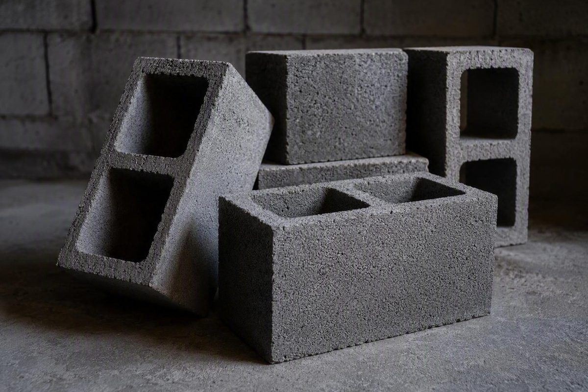
The most frequently encountered full-size concrete masonry unit in U.S. construction is nominally 8 × 8 × 16 inches. That designation does not mean the block itself should measure exactly 8 inches wide, 8 inches high, and 16 inches long. A corresponding precision CMU typically has specified dimensions of 7 5/8 × 7 5/8 × 15 5/8 inches. Dimensions are conventionally written as width or depth × height × length. A published CMU dimensional guide documents this common nominal and specified-size relationship.
The difference is easiest to understand in the unit’s face dimensions. A 7 5/8-inch specified height plus a typical 3/8-inch bed joint produces an 8-inch nominal course; a 15 5/8-inch specified length plus a typical 3/8-inch head joint produces a 16-inch horizontal module. Width follows the corresponding nominal-versus-specified thickness convention, but that does not mean there is a literal mortar joint running across the wall thickness.
That distinction is central to reading any CMU size chart:
- Nominal dimensions coordinate the masonry layout.
- Specified dimensions define the dimensions designated for manufacturing, construction, and design.
- Actual dimensions are measurements taken from an individual unit.
Standard CMU dimensions at a glance
CMU dimensions are conventionally written in this order:
width or depth × height × length
Accordingly, an 8 × 8 × 16-inch unit is nominally 8 inches wide, 8 inches high, and 16 inches long. The width is also commonly used to identify the unit and its wall-thickness module: an “8-inch CMU” generally means a unit with a nominal width of 8 inches.
For standard precision units, the following table is a useful preliminary reference. It uses specified size, rather than “actual size,” because an individual manufactured unit can vary from the specified dimensions within the applicable tolerance.
| Nominal size, W × H × L | Typical specified size, W × H × L |
|---|---|
| 4 × 8 × 16 in. | 3 5/8 × 7 5/8 × 15 5/8 in. |
| 6 × 8 × 16 in. | 5 5/8 × 7 5/8 × 15 5/8 in. |
| 8 × 8 × 16 in. | 7 5/8 × 7 5/8 × 15 5/8 in. |
| 10 × 8 × 16 in. | 9 5/8 × 7 5/8 × 15 5/8 in. |
| 12 × 8 × 16 in. | 11 5/8 × 7 5/8 × 15 5/8 in. |
These nominal and specified dimensions are documented in Angelus Block’s precision-unit dimensional table.
The width changes across the table, but the usual full-unit face remains nominally 8 inches high by 16 inches long. That common face module lets walls of different nominal widths follow the same general coursing system.
The 8 × 8 × 16-inch CMU is common, but it is neither the only recognized size nor a universal product for every wall. Industry guidance identifies typical nominal face dimensions of 8 by 16 inches and nominal widths of 4, 6, 8, 10, 12, 14, and 16 inches. It also cautions that configurations and regional availability vary, so recognition of a dimension does not guarantee that a local supplier stocks it. CMHA summarizes these common dimensions and availability qualifications.
Several practical consequences follow:
- A request for “standard block” is incomplete unless the width is stated.
- Nominal width does not establish core arrangement, solid content, weight classification, finish, or structural suitability.
- A specialty unit can occupy the same nominal envelope as a regular unit while having different webs, cores, ends, or faces.
- Fourteen- and 16-inch nominal widths may be recognized without being routinely stocked in a particular market.
- Architectural or manufacturer-specific products may use other heights, lengths, proportions, and profiles.
For preliminary drawings, estimates, and modular studies, the table is a sound starting point. For final specifications or ordering, use current product data from the selected manufacturer and plant.
Nominal, specified, and actual dimensions are not interchangeable
The three principal dimensional terms answer different questions.
Nominal dimensions describe the coordinated masonry module. For unit height and length, they generally combine the specified unit dimension with the intended bed- or head-joint allowance. Nominal dimensions are useful for setting out courses, wall lengths, openings, piers, and other elements on a modular grid. Nominal width identifies the coordinated wall-thickness category rather than the finished thickness of the complete wall assembly.
Specified dimensions are the dimensions designated for manufacturing the units or constructing the masonry. They are used for technical product requirements and design calculations. For the familiar precision CMU, 7 5/8 × 7 5/8 × 15 5/8 inches is the typical specified size corresponding to an 8 × 8 × 16-inch nominal module.
Actual dimensions are measured dimensions taken from an individual manufactured unit. An actual measurement may equal the specified dimension, but the two terms do not mean the same thing. Manufacturing tolerances mean a compliant unit need not measure exactly the catalog’s specified value. This distinction among nominal, specified, and actual dimensions is set out in manufacturer technical guidance.
The terminology explains an apparent disagreement among CMU references. Many general-purpose charts label 7 5/8 × 7 5/8 × 15 5/8 inches as the “actual size” of an 8 × 8 × 16-inch block. That shorthand contrasts the physical block with the nominal space coordinated for the unit and its joints. More precise technical usage labels the tabulated value as the specified dimension and reserves actual dimension for a measurement of an individual unit.
For drawings and specifications, the more precise terminology is safer:
| Term | What it describes | Typical use |
|---|---|---|
| Nominal dimension | Coordinated masonry module or nominal wall-thickness category | Plans, elevations, coursing, overall layout |
| Specified dimension | Designated manufacturing or construction dimension | Product requirements, technical details, calculations |
| Actual dimension | Measurement of an individual unit | Field checks, inspection, existing-condition surveys |
Dimension order matters just as much as terminology. CMU dimensions are stated as width × height × length, not according to whichever face appears most prominent in a drawing.
Consider these two designations:
- 8 × 4 × 16 inches: 8 inches nominally wide, 4 inches high, and 16 inches long.
- 4 × 8 × 16 inches: 4 inches nominally wide, 8 inches high, and 16 inches long.
The first describes a wider, half-height unit. The second describes a narrower unit with the usual nominal course height. Reversing width and height therefore identifies a different product.
Clear notation is especially important in schedules, details, and purchasing documents. A useful unit designation may identify:
- nominal width, height, and length;
- specified dimensions where they govern a detail;
- unit configuration or shape;
- finish and face treatment;
- weight classification, if relevant;
- applicable product standard;
- manufacturer and product reference, when selected.
Avoid placing a table of nominal dimensions beside a detail drawn to specified dimensions without labeling both. A reader should not have to infer whether “8 inches” describes the wall module, the unfinished unit width, or the finished assembly.
How the 3/8-inch mortar joint creates the CMU module
Common U.S. modular CMU sizing typically assumes a 3/8-inch mortar joint. The most direct relationships occur vertically at bed joints and horizontally at head joints.
Vertically:
7 5/8-in. specified unit height + 3/8-in. bed joint = 8-in. nominal course
Horizontally:
15 5/8-in. specified unit length + 3/8-in. head joint = 16-in. nominal length
These calculations reflect the standard relationship between common CMU dimensions and a typical 3/8-inch joint. Archtoolbox documents the same unit sizes and joint basis.
Width requires more careful wording. A nominal 8-inch precision unit is typically specified as 7 5/8 inches wide before coatings, furring, insulation, cladding, or other finishes are added. The nominal 8-inch designation is the coordinated wall-thickness category. It should not be read as proof that a 3/8-inch mortar joint physically completes the width of every wall.
Diagram: physical CMU, joints, and nominal box
VERTICAL MODULE

      top of nominal 8-in. course
      ┌─────────────────────────────┐
      │  Bed joint: 3/8 in.         │
      ├─────────────────────────────┤
      │                             │
      │  Precision CMU              │
      │  specified height: 7 5/8 in.│
      │                             │
      └─────────────────────────────┘

      7 5/8 in. + 3/8 in. = 8 in. nominal


HORIZONTAL MODULE

      ┌───────────────────────────┬─────────┐
      │ Precision CMU             │ Head    │
      │ specified length:         │ joint:  │
      │ 15 5/8 in.                │ 3/8 in. │
      └───────────────────────────┴─────────┘

      15 5/8 in. + 3/8 in. = 16 in. nominal


WALL-THICKNESS CONVENTION

      Nominal width: 8 in.
      Typical specified unit width: 7 5/8 in.

      This is a thickness convention, not a diagram
      of a mortar joint across the wall width.
The diagram explains modular spacing rather than depicting mortar distributed around every surface of an isolated unit. A wall contains repeated bed and head joints; the module assigns the joint allowance to the coordinated spacing between successive units and courses.
Do not overextend the subtraction rule. Saying that a precision CMU is typically specified 3/8 inch smaller than its nominal dimensions is a coordination convention. It is not a promise that every block removed from a pallet will measure exactly 3/8 inch less than nominal in every direction. Actual manufactured dimensions can vary within the applicable tolerance, and textured surfaces can receive different dimensional treatment.
The standard arithmetic also should not be applied automatically when a project uses a different joint thickness. If the intended bed joint is not 3/8 inch, calculate the course height directly:
specified unit height + intended bed-joint thickness
Likewise, calculate horizontal spacing as:
specified unit length + intended head-joint thickness
Changing the joint without changing the unit can cause accumulated wall height or length to drift away from the usual 8- or 16-inch grid. The resulting layout should be calculated from the selected product and project details, with field tolerances and base conditions considered separately.
Full blocks, half blocks, half-height units, and specialty shapes
A full rectangular CMU is only one member of a larger unit family.
A standard half block is nominally 8 inches long rather than 16 inches long. Its typical specified length is 7 5/8 inches.
| Nominal half-block size, W × H × L | Typical specified size, W × H × L |
|---|---|
| 4 × 8 × 8 in. | 3 5/8 × 7 5/8 × 7 5/8 in. |
| 6 × 8 × 8 in. | 5 5/8 × 7 5/8 × 7 5/8 in. |
| 8 × 8 × 8 in. | 7 5/8 × 7 5/8 × 7 5/8 in. |
| 10 × 8 × 8 in. | 9 5/8 × 7 5/8 × 7 5/8 in. |
| 12 × 8 × 8 in. | 11 5/8 × 7 5/8 × 7 5/8 in. |
These representative half-block dimensions appear in Jandris Block’s CMU product table. They do not establish that every supplier stocks every listed width.
A half-height unit is commonly nominally 4 inches high. Product ranges may include nominal configurations such as:
- 6 × 4 × 16 inches;
- 8 × 4 × 16 inches;
- 12 × 4 × 16 inches.
With the conventional modular relationship, the specified height of a nominal 4-inch-high precision unit is typically 3 5/8 inches. Half-height units can resolve a 4-inch vertical module, but availability depends on width, configuration, finish, and local manufacturing.
Recurring specialty categories include:
- bond-beam units;
- knockout bond beams;
- lintel units;
- open-end and double-open-end units;
- sash units;
- corner units;
- cap units;
- pilaster and column units;
- bullnose units;
- starter units;
- solid or partially solid units.
The nominal outer envelope does not tell the complete story. An 8 × 8 × 16-inch bond-beam unit may occupy the same nominal module as a regular 8 × 8 × 16-inch unit while having different webs or knockouts. An open-end unit changes access to the cell. A bullnose unit changes the profile of an exposed edge. A corner unit can have a finished end.
Manufacturer catalogs illustrate why “specialty shape” does not necessarily mean “different overall size.” Standard, bond-beam, open-end, corner, bullnose, half-length, and half-height products can appear within related nominal size families, while not every combination is stocked. RCP’s precision-block catalog lists such families and warns that special ordering may be required.
Conversely, not every specialty unit fits a simple width × height × length comparison. An L-shaped corner can require another leg dimension. Some lintel configurations use proportions or orientations unlike a conventional full unit. Pilaster and column units may have footprints intended for a specific assembly rather than a straight wall. Profiles, faces, and end conditions can matter as much as the nominal envelope.
Generic schedules should therefore establish design intent rather than invent a local product range. Before completing details, obtain manufacturer drawings for each specialty unit and confirm:
- dimensional order;
- specified overall dimensions;
- core and web geometry;
- open or closed ends;
- bearing surfaces;
- finish locations;
- compatible companion units;
- current production and local availability.
ASTM C90 dimensions, tolerances, and textured-unit exceptions
ASTM C90 is the commonly encountered U.S. specification for load-bearing dry-cast concrete masonry units. It addresses product requirements and permissible dimensional variation, but it should not be described as mandating one universal nominal block size. CMUs are manufactured in multiple widths, configurations, and finishes.
CMHA’s summary of ASTM C90 reports that the actual overall width, height, and length of a standard precision unit may generally vary by ±1/8 inch from its specified dimensions, subject to exceptions for certain architectural surfaces. CMHA also emphasizes that the edition referenced by the applicable code or project specification matters because requirements can change between editions. The association’s technical overview provides this standards context and tolerance summary.
That tolerance reinforces the difference among the dimensional terms. For a nominal 8 × 8 × 16-inch unit:
- 8 × 8 × 16 inches is the nominal module.
- 7 5/8 × 7 5/8 × 15 5/8 inches is the typical specified size of a corresponding precision unit.
- The actual size is whatever the individual unit measures, subject to the applicable specification, tolerance, and surface exceptions.
A dimension taken from one unit should not automatically be treated as the dimension of the full production run. Nor should an estimator assume that every permitted variation will accumulate in the same direction. Masonry construction accommodates normal product variation through joint control, coursing, and workmanship, but the drawings still need a coherent modular basis.
Precision units provide the cleanest basis for a standard CMU size chart because their formed surfaces are comparatively regular. Architectural textures complicate measurement.
For split-face units, Angelus Block states that the reported ±1/8-inch limit applies to non-split overall dimensions rather than requiring the irregular split surface to behave like a precision surface.
For Angelus Block’s Slumpstone products, the manufacturer states that the reported ±1/8-inch tolerance applies only to height. These are manufacturer-published explanations of textured-unit treatment, not universal rules for every textured CMU made by every producer.
These exceptions have practical consequences. If a finish face must align with adjacent materials, a nominal envelope alone may not define the visible plane closely enough. Field measurements should be taken from the surfaces to which the applicable tolerance applies.
When specifying CMU, identify the standard edition required by the project rather than relying solely on an undated phrase such as “conform to ASTM C90.” Check the applicable code, contract documents, and current manufacturer data together. A summary chart cannot reproduce every definition, test method, exception, and finish provision in the complete standard.
Using the 8-inch module to lay out walls and openings
Standard concrete masonry modules are typically 8 inches vertically and horizontally, while 4-inch modules are also used in some applications. Full units coordinate naturally with 16-inch horizontal increments, and half units coordinate with 8-inch increments. This grid turns a catalog size into a practical layout system.
A simple vertical example shows the principle:
10 nominal courses × 8 inches per course = 80 inches
The 80-inch result is a coordination dimension, not a guarantee that construction can proceed without control. The first course must respond to the supporting surface, and masons must manage joint thickness, level, unit variation, and the required final elevation. Nevertheless, the module gives drawings, openings, estimates, and masonry work a common basis. CMHA’s modular-layout guidance documents the 8-inch module and the role of modular coordination.
Horizontally:
- one full nominal unit occupies a 16-inch module;
- one half nominal unit occupies an 8-inch module;
- two half-unit modules equal one full-unit module;
- wall lengths in 8-inch increments can generally be studied using combinations of full and half units.
Modular planning can reduce field cutting and dependence on nonstandard units. It also helps coordinate several related conditions.
Wall lengths. Dimensioning to full- or half-unit increments can allow a wall to terminate with standard units rather than narrow cuts.
Piers. A pier width should be checked against the unit arrangement and bond pattern, not merely rounded to a convenient architectural dimension.
Openings. Jamb locations and opening widths affect unit lengths on both sides. An opening can be modular in width yet still produce awkward masonry if its centerline or the adjacent wall segments are not coordinated.
Corners and intersections. Running bond can require alternating arrangements at corners. Required corner units, full units, and half units should be studied course by course.
Jambs and terminations. Open-end, sash, corner, or half units may simplify a condition, but their availability must be confirmed before the detail depends on them.
Control joints. Joint locations should be coordinated with the bond pattern and unit layout rather than inserted after an elevation is complete.
Bond beams and reinforced cells. Horizontal and vertical features need compatible cell and web arrangements. A seemingly minor cut can interfere with the intended alignment.
Nonmodular layouts can interrupt bond patterns and cell alignment. In reinforced or grouted construction, those disruptions can complicate reinforcement placement, grout consolidation, and control-joint construction. Those consequences are reasons to coordinate dimensions early, not instructions for project-specific structural design.
Modular planning does not mean every building dimension must be a multiple of 8 inches. Openings, structure, finishes, accessibility requirements, equipment, and other systems impose independent constraints. The goal is to identify departures from the masonry module early enough to resolve them deliberately.
A useful coordination workflow is:
- Establish the nominal wall module.
- Lay out major corners, intersections, and openings.
- Test alternating courses where running bond is intended.
- Identify required full, half, corner, open-end, and bond-beam units.
- Check cell alignment at reinforced or grouted locations.
- Confirm specialty-unit availability.
- Locate unavoidable cuts where they can be detailed and built rationally.
- Coordinate finished dimensions separately from nominal masonry dimensions.
This is dimensional coordination, not structural design. The module can help position openings, cells, and bond beams, but it cannot establish required reinforcement, grout, bearing, lintel design, or structural capacity.
Metric CMUs are a separate modular system
A commonly cited metric concrete-masonry module is 200 × 200 × 400 mm nominal, with corresponding unit dimensions of 190 × 190 × 390 mm. The 10 mm difference provides the modular allowance for mortar joints.
| Metric description | Width × height × length |
|---|---|
| Nominal metric module | 200 × 200 × 400 mm |
| Corresponding unit dimensions | 190 × 190 × 390 mm |
| Typical modular joint allowance | 10 mm |
CMHA’s modular guidance provides these metric dimensions and notes that inch-pound units are approximately 2% larger than their metric counterparts. The metric module is therefore a counterpart to the U.S. inch-based module, not an exact mathematical conversion of it. CMHA documents the complete nominal and unit dimensions for the metric module.
In Canadian metric practice, a 190 mm-high block plus a typical 10 mm mortar joint creates a 200 mm nominal course. The Canada Masonry Design Centre discusses this relationship in its Canadian masonry-coursing guidance.
Keep the two systems separate in schedules and details:
U.S. inch-based reference Nominal: 8 × 8 × 16 in. Typical specified precision unit: 7 5/8 × 7 5/8 × 15 5/8 in. Typical bed- and head-joint basis: 3/8 in.
Metric modular reference Nominal: 200 × 200 × 400 mm Corresponding unit: 190 × 190 × 390 mm Typical joint basis: 10 mm
Do not place the metric dimensions in parentheses after the inch dimensions as though one were an exact conversion of the other. If a project is designed around a metric masonry system, use the metric module consistently and verify the applicable Canadian, regional, or project-specific standards. These values are a limited modular reference, not a comprehensive international CMU size table.
What to verify before drawing, specifying, or ordering CMU
A generic chart is useful for preliminary coordination, but it is not a product submittal or purchase order. Before incorporating a unit into final construction documents—or placing an order—verify the following.
Dimensional checklist
- Nominal width: Which wall-thickness module governs?
- Nominal height and length: Is the unit full-height, half-height, full-length, half-length, or another module?
- Specified dimensions: What dimensions does the selected producer designate for manufacture and design?
- Dimension order: Are the values clearly written as width × height × length?
- Applicable tolerance: Which dimensions and surfaces are subject to the stated tolerance?
- Finished assembly thickness: Have coatings, furring, insulation, cladding, and other layers been added separately from the CMU width?
Product checklist
- Unit configuration: Regular, solid, bond beam, knockout, lintel, open-end, sash, corner, cap, pilaster, column, bullnose, starter, or another shape?
- Core and web geometry: Does it support the intended detailing, grouting, and reinforcement arrangement?
- Finish or texture: Precision, split-face, slump-textured, ground-face, or another architectural finish?
- Faces and ends: Which surfaces are finished, split, bullnosed, open, or closed?
- Weight classification: Has the relevant classification been identified where it affects the specification or assembly?
- Companion units: Are half units, corners, bond beams, and other required shapes compatible and available?
Standards and procurement checklist
- Referenced standard and edition: Does it match the applicable code and project specification?
- Manufacturer: Has a suitable product line been identified?
- Plant or region: Are the required products manufactured or distributed locally?
- Current product data: Are the dimensions and configurations current?
- Quantity: Does the takeoff distinguish regular units from specialty units and allow appropriately for cuts, waste, and field conditions?
- Lead time: Are nonstock sizes, colors, textures, or shapes being treated as special orders?
- Submittals and samples: Are they required to confirm appearance, geometry, and compatibility?
The common nominal widths shown in the main chart are widely documented. Wider, specialty, and architectural products can be more market-dependent. Even within a familiar width, a supplier may not stock every half unit, finish, corner, open-end, or bond-beam configuration.
Finish selection also affects detailing. Slump textures do not behave dimensionally like precision faces. Bullnose edges alter profiles at openings and corners. Open-end units change placement and access. Solid content, cores, and webs can differ even where nominal envelopes appear identical.
Most importantly, dimensional selection is not structural selection. General CMU references likewise caution that dimensions alone do not determine structural suitability. A CMU size reference expressly recommends selection according to structural requirements and applicable codes.
The practical rule is straightforward:
- Use nominal dimensions for modular coordination.
- Use specified dimensions for technical detailing and product requirements.
- Use measured actual dimensions for field verification.
For the common 8-inch CMU, coordinate around the 8 × 8 × 16-inch nominal module, detail the corresponding precision product around its typical 7 5/8 × 7 5/8 × 15 5/8-inch specified size, and measure actual units where field conditions or tolerances matter. Confirm the selected shape, finish, tolerance, standard edition, and availability before construction or ordering.
Frequently asked questions
What is the standard size of a concrete masonry unit?
The most frequently encountered U.S. full-size CMU is nominally 8 × 8 × 16 inches, written as width × height × length. A corresponding precision unit typically has specified dimensions of 7 5/8 × 7 5/8 × 15 5/8 inches. A manufacturer’s dimensional overview identifies the same common nominal and physical-size relationship.
That is the common size, not the only recognized configuration. Other nominal widths are available, and local manufacturer offerings vary.
What are the actual dimensions of an 8 × 8 × 16-inch CMU?
The dimensions often called the “actual size” in general-reference charts are 7 5/8 × 7 5/8 × 15 5/8 inches. In more precise technical usage, those are the typical specified dimensions of a nominal 8 × 8 × 16-inch precision CMU. The actual dimensions are the measurements taken from an individual manufactured unit and may vary within the applicable tolerance. This nominal-size relationship and the unfinished 7 5/8-inch wall thickness are summarized in a CMU dimensional guide.
Does a CMU’s nominal size include the mortar joint?
Generally, nominal height and length represent the coordinated unit-and-joint module. With a typical 3/8-inch joint, a 7 5/8-inch specified unit height plus a bed joint coordinates to an 8-inch course, while a 15 5/8-inch specified unit length plus a head joint coordinates to a 16-inch horizontal module. CMHA-based construction guidance describes this common nominal relationship.
Nominal width is better understood as the wall-thickness category. A nominal 8-inch unit is typically specified as 7 5/8 inches wide, but that difference should not be interpreted as a literal mortar joint across the wall width.
If a project uses a different bed- or head-joint thickness, calculate the layout from the selected unit and intended joint instead of applying the standard arithmetic automatically.
What size is a standard half block or half-height CMU?
A standard half block is nominally 8 inches long, with a typical specified length of 7 5/8 inches. An 8-inch-wide example is nominally 8 × 8 × 8 inches and typically specified as 7 5/8 × 7 5/8 × 7 5/8 inches. Representative half-block dimensions are listed in Jandris Block’s product table.
A half-height CMU is commonly nominally 4 inches high. Product lines may include nominal configurations such as 6 × 4 × 16, 8 × 4 × 16, and 12 × 4 × 16 inches. Widths, configurations, finishes, and local stock must be confirmed with the selected supplier.
Are CMU sizes and tolerances the same for every manufacturer and finish?
No. Precision units provide the clearest basis for standard dimensional tables, but available sizes, specialty shapes, core arrangements, and finishes differ among manufacturers and regions. Split-face and slump-textured products can also receive different dimensional treatment from regular precision units.
Confirm the nominal and specified dimensions, applicable tolerance, controlled measurement surfaces, finish, configuration, referenced standard edition, and current availability for the selected product. Manufacturer catalogs themselves warn that listed dimensions may be nominal and that some shapes require special ordering.
A generic CMU chart is a coordination aid—not a substitute for current manufacturer data, project specifications, applicable codes, or project engineering.