
How Steel and Concrete Work Together—and Where the Details Matter
Concrete containing reinforcing bars is reinforced concrete: a composite material in which concrete, steel, and the bond between them work together. Concrete…
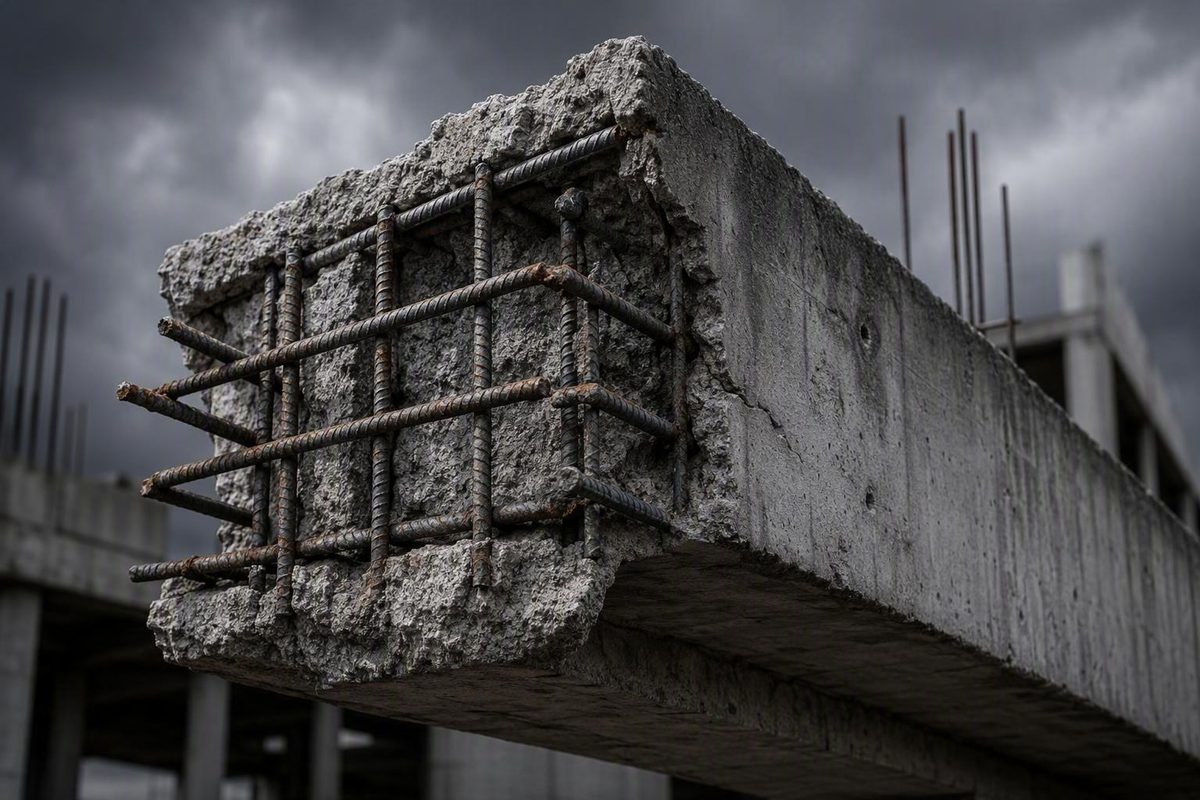
Concrete containing reinforcing bars is reinforced concrete: a composite material in which concrete, steel, and the bond between them work together. Concrete performs well in compression but is comparatively weak in tension. Correctly designed reinforcement carries tensile forces and may also contribute to shear resistance, crack control, and ductility.
The principle is simple; the execution is not. A bar contributes as intended only when its size, grade, position, anchorage, cover, and continuity match the structural design—and when it remains in that position through concrete placement.
This guide explains how reinforced concrete works, how to read reinforcement information, what to inspect before and during a pour, how common reinforcement options differ, and how to perform a slab takeoff without confusing quantity estimation with structural design.
Critical distinction: A calculator can estimate steel quantities. It cannot determine whether a slab, wall, footing, beam, column, or other member is safe. Approved drawings, applicable requirements, equipment instructions, and project-specific engineering govern.
What concrete with rebar is—and why the pairing works
Concrete containing embedded reinforcing bars is commonly called reinforced concrete. “Rebar” is short for reinforcing bar or reinforcement bar.
The two materials perform complementary roles:
- Concrete carries compressive forces effectively.
- Rebar is positioned to carry tensile forces that plain concrete handles comparatively poorly.
- The composite member uses both materials, acting together, to resist its intended loads.
Longitudinal reinforcement is therefore commonly placed near the lower face—but still embedded within the concrete—so that it crosses expected cracks and carries tension.
The pattern is not universal. Reinforcement must therefore follow the calculated force path rather than a customary top, middle, or bottom position.
Properly designed steel may also contribute to shear resistance and ductile behavior. The exact arrangement depends on the member, loading, geometry, and governing design.
A composite system, not steel scattered through concrete
Reinforced concrete is not ordinary concrete with extra strength distributed wherever bars happen to fit. The components must act together.
That composite action requires:
- A force path from the loaded concrete into the reinforcement.
- Adequate interaction and anchorage between the concrete and steel.
- Reinforcement positioned where the design requires it.
- Continuity through embedment, laps, hooks, couplers, or adjoining members as detailed.
- Sufficient surrounding concrete for the specified position, placement, and environmental protection.
- Concrete that is properly placed, consolidated, jointed, and cured.
Steel and concrete also have similar thermal-expansion behavior, which limits differential movement between them as temperatures change. Deformations on a typical bar improve its mechanical interaction with the surrounding concrete. These features help the materials act as a composite system rather than as independent components. A general summary appears in this overview of reinforcing bar behavior.
Reinforcement manages cracks; it does not promise crack-free concrete
Rebar does not eliminate every cracking mechanism.
Depending on the design, reinforcement may:
- Carry tension after concrete cracks.
- Distribute movement among multiple cracks.
- Limit crack widths.
- Maintain continuity across cracks.
- Contribute to ductile behavior.
Conversely, an apparently uncracked surface does not prove that reinforcement, support conditions, or load capacity are adequate. Crack location, width, pattern, activity, exposure, and structural context all matter.
Primary and secondary reinforcement
Two broad functional categories are useful:
- Primary reinforcement helps carry calculated structural loads.
- Secondary reinforcement mainly addresses shrinkage- and temperature-related stresses.
The distinction matters when considering substitutions. A material accepted for distributed shrinkage control is not automatically suitable for replacing bars that resist beam flexure, column forces, cantilever action, or another primary demand. The Fiber Reinforced Concrete Association’s guidance similarly distinguishes primary reinforcement from shrinkage-and-temperature reinforcement.
How forces reach the steel: bond, anchorage, laps, and bar position
A bar does not become useful merely because concrete surrounds it. Force must transfer between the hardened concrete and the reinforcement, and the bar must be anchored or continued so it can develop the force required by the design.
Bond and bar deformations
Most conventional reinforcing bars have ribs or other surface deformations. These features improve mechanical interaction with concrete and reduce slippage compared with a smooth surface.
Deformations alone do not establish a complete force path. The reinforcement must also have adequate embedment and termination, while the surrounding concrete must be placed and consolidated around it. Misplaced steel, inadequate anchorage, or severe congestion can prevent the installed assembly from behaving as intended.
Development, embedment, and hooks
Development is the process by which interaction between a bar and the surrounding concrete enables the reinforcement to reach the force required by the design.
A design may use:
- Straight embedment beyond a critical region.
- Hooks or bends.
- Mechanical anchorage or couplers.
- Continuation into an adjoining member.
- Surrounding reinforcement or confinement.
- A combination of these measures.
There is no universal development length or hook detail suitable for every project. Requirements depend on the bar, concrete, coating, spacing, cover, confinement, member geometry, loading, and applicable design provisions.
A visually substantial embedment is not necessarily adequate. Anchorage is a calculated part of the load path, not a judgment made by appearance.
Lap splices continue force between bars
When one bar cannot provide the required continuous run, a design may use a lap splice.
Drawings may require splices to be staggered, placed outside particular regions, or replaced with mechanical couplers. Concentrating many splices in one area can also create placement congestion.
Do not infer lap length from a generic multiple of bar diameter. Bar size, coating, concrete, confinement, member type, and stress conditions can all affect the required detail.
Position follows the force path
Reinforcement is deliberately placed in regions where the design expects it to work:
- Bottom steel may resist positive bending in a simply supported span.
- Top steel may resist negative bending over supports.
- Vertical bars may carry axial and bending effects in walls or columns.
- Transverse reinforcement may contribute to shear resistance or confinement.
- Bars around openings may redirect interrupted force paths.
- Dowels may transfer force across a joint or into another member.
- Additional edge or corner bars may address localized geometry and restraint.
A grid lying on the subgrade is not equivalent to the same grid supported at its specified elevation. Nor can reinforcement near the middle of a section automatically perform a role assigned to top or bottom steel. Acceptable positioning and tolerances must come from the controlling documents.
An illustrative section detail
A useful section drawing should show both the concrete geometry and the intended reinforcement position. The following sketch is conceptual only; it contains no project-ready dimensions.
             Illustrative downward load
                      ↓  ↓  ↓

        ┌────────────────────────────────┐
        │       Compression region       │
        │                                │
        │       Bar mark T1  ─────┐      │
        │                         └─ hook│
        │                                │
        │   B1 ════════════              │
        │          ════════════ B1       │  ← lap between bars
        │      △       △       △         │  ← chairs/spacers
        │   Tension region under the     │
        │   stated loading assumption    │
        └────────────────────────────────┘
          ↑                            ↑
        concrete face              concrete face

        Clear cover is measured from a concrete face
        to the nearest outer surface of the bar.
The tension region shown applies only to the stated illustrative loading. Support conditions, continuity, uplift, lateral loads, and construction stages can produce a different force pattern.
Reading a rebar schedule: size, grade, spacing, and cover
A reinforcement callout combines several independent requirements. Size, grade, spacing, cover, and elevation are not interchangeable inputs.
Bar size
In customary U.S. notation, commonly encountered bar numbers generally correspond to nominal diameter in eighths of an inch:
| Bar designation | Nominal diameter |
|---|---|
| #3 | 3/8 in. |
| #4 | 1/2 in. |
| #5 | 5/8 in. |
| #8 | 1 in. |
These are identification facts, not recommendations for a particular member. The U.S. size relationships are also listed in the Raken rebar reference, which cautions that final requirements need engineering input.
Bar size affects steel area, weight, bend geometry, congestion, and anchorage. Replacing several smaller bars with fewer larger bars—or the reverse—is not a field equivalency unless the responsible designer approves it.
Grade
A bar’s grade denotes its minimum yield strength. For example, Grade 60 denotes a minimum yield strength of 60,000 psi. Size and grade are separate properties: two bars may have the same nominal diameter but different grades. The relationship between grade and minimum yield strength is summarized in this rebar grade and size guide.
A higher grade is not automatically an acceptable substitute. The reinforcement design, material specification, bends, anchorage, and splice requirements may be tied to the stated grade. Check bar markings and documentation where the project requires verification.
Spacing, clearance, cover, and elevation
These terms describe different aspects of reinforcement geometry:
- Spacing is the specified distance between bars, commonly measured on center.
- Clear spacing is the open distance between adjacent bar surfaces.
- Edge clearance is a layout or estimating offset from an edge; drawings or calculator instructions must define exactly what it measures.
- Concrete cover is the distance from a bar’s outer surface to the concrete surface.
- Centerline offset is the distance from a concrete edge to the centerline of a bar.
- Bar elevation locates a bar or mat vertically within the member.
- Layer separation is the clear distance between reinforcement layers.
If a drawing gives clear cover, c, and the bar diameter is d_b, the corresponding centerline offset is:
e = c + d_b ÷ 2
That geometric conversion matters because many calculators request an edge offset without clearly distinguishing a bar centerline from the bar surface.
Concrete edge │<---- centerline offset e ---->● bar center
              │<--- clear cover c --->(bar surface)
                                       <d_b>
Cover helps separate steel from environmental exposure and places the bar within the intended section. Changing cover also changes reinforcement position, so adding extra cover is not automatically a harmless durability improvement.
Required cover varies with the member, bar, exposure, casting condition, and governing requirements. Supplier examples should not be copied into project details as universal values.
Use the approved documents: Bar size, grade, spacing, cover, laps, hooks, bends, and layout must come from approved plans, applicable requirements, and project-specific engineering. Request clarification when the drawings conflict or omit a necessary dimension.
A practical schedule-reading format
A reinforcement schedule may use columns such as:
| Bar mark | Size | Grade | Spacing or quantity | Location or function | Drawing reference |
|---|---|---|---|---|---|
| Project-defined mark | Specified size | Specified grade | Specified centers or count | Member, face, layer, or zone | Plan, section, or detail |
Other columns may identify coating, shape, cut length, lap designation, or coupler type. Do not invent a missing entry. Trace each bar mark from the schedule to the relevant plan, section, and detail so that it represents a physical bar in a defined location.
From drawings to pour: placing and inspecting reinforcement
Correct installation is a controlled sequence. It should not be improvised as concrete arrives.
1. Review the construction documents
Before cutting or distributing steel, identify:
- The current drawing revision.
- Applicable general notes and specifications.
- Bar marks, sizes, grades, coatings, and quantities.
- Plan dimensions, sections, and details.
- Required layers and elevations.
- Laps, hooks, bends, dowels, couplers, and terminations.
- Openings, sleeves, embeds, anchors, and joints.
- Inspection hold points.
- Conflicts with other building systems.
Resolve discrepancies through the project’s formal process rather than selecting the easiest detail to build.
2. Prepare the base, forms, and reference lines
Verify the concrete geometry before locating the steel. Check forms, blockouts, base conditions, specified elevations, openings, and reference lines. Where included in the project documents, coordinate vapor-retarder arrangements and other work below the slab.
Reinforcement cannot compensate for an incorrectly sized form, misplaced opening, or unsuitable supporting condition.
3. Verify the delivered reinforcement
Compare bundle tags and bar markings with the schedule. Check:
- Size and grade.
- Coating or material.
- Length and shape.
- Quantity.
- Bar marks.
Set aside unidentified or nonconforming material. Visual diameter alone does not verify grade or coating requirements.
4. Cut and bend as detailed
Use equipment suited to the specified reinforcement and fabrication operation. Do not alter bar shapes or make undocumented substitutions simply to resolve a field conflict.
Basic installation equipment and safety provisions commonly include suitable cutting and bending tools, tie wire and tying tools, measuring equipment, specified chairs or spacers, gloves, eye protection, protective footwear, and current drawings. Cutting and handling reinforcing steel can create sharp edges, flying debris, pinch points, and handling hazards, so work must follow the project safety plan and tool instructions. These general precautions are reflected in the installation and safety workflow from Bracing Systems.
5. Arrange, tie, and support the bars
Place reinforcement in a sequence that permits the remaining work to be installed without unnecessary cutting or displacement.
Chairs, bolsters, and spacers maintain bar elevation and cover. Supports must suit the form, base, reinforcement arrangement, and project requirements. Bars should not rest directly on soil, and workers should not rely on pulling a grid upward by hand while concrete is being discharged.
6. Inspect before concrete placement
A disciplined pre-pour inspection should cover the following categories.
Documents and identification
- Correct drawing revision is available.
- Bar marks correspond to the schedule.
- Size, grade, material, coating, and shape are verified.
- Approved changes are documented.
Geometry
- Member and form dimensions are correct.
- Bar count and spacing match the drawings.
- Top, bottom, inside, and outside layers are correctly oriented.
- Cover, edge offsets, and layer separation are maintained.
- Supports are stable and located as required.
- Reinforcement does not sag out of position.
Continuity and anchorage
- Required laps are present and correctly located.
- Hooks and bends face the intended direction.
- Dowels and starters have the specified projection and position.
- Corner and intersection details are complete.
- Specified couplers are installed as detailed.
Coordination
- Openings, sleeves, embeds, anchors, and blockouts are accounted for.
- Reinforcement has not been cut to accommodate uncoordinated work.
- Sufficient access remains for concrete placement and consolidation.
- Congested regions have a workable placement sequence.
- Future drilling and anchoring zones are coordinated where relevant.
Condition and safety
- Coated bars have been inspected for handling damage.
- Loose wire, offcuts, and debris have been removed.
- Exposed ends are managed under the project safety plan.
- Access does not require workers to rely on unstable reinforcement.
The cited installation guide follows the same broad progression—layout, cutting, bending, tying, support, inspection, and monitoring—but any sample dimensions in a commercial guide remain examples rather than universal project requirements.
7. Monitor reinforcement during the pour
A successful pre-pour inspection does not guarantee that the reinforcement will remain in place. During concrete placement, watch for:
- Foot traffic depressing a mat.
- Hoses dragging reinforcement sideways.
- Concrete discharge shifting a grid or cage.
- Supports overturning or sinking into the base.
- Top bars sagging or moving.
- Lapped bars separating.
- Placement or consolidation activity disturbing reinforcement.
- Congested areas failing to fill adequately.
Provide planned access where required. Correct visible displacement before the affected reinforcement is buried.
Frequent installation errors
Recurring problems include:
- Incorrect bar spacing or count.
- Inadequate or excessive cover relative to the detail.
- Reversed reinforcement layers.
- Missing corner bars, dowels, hooks, or laps.
- Steel cut around an uncoordinated penetration.
- Damaged coatings.
- Missing, misplaced, or unstable supports.
- Congestion that obstructs concrete placement.
- Movement caused by workers, hoses, discharge, or consolidation.
- Unapproved substitutions.
Photographs and inspection records are useful documentation, but they do not make nonconforming work acceptable. Reinforcement is most accessible—and generally easiest to correct—before concrete covers it.
Cracking, corrosion, and why cover is a durability detail
Cracking and failure are not synonymous. Concrete cracks for many reasons, and the importance of a crack depends on its cause, location, pattern, width, activity, exposure, and the function of the member.
Similar-looking symptoms can have different causes and consequences.
How corrosion can lead to spalling
Embedded carbon steel is ordinarily protected by its concrete environment. That protection may deteriorate when moisture and aggressive agents reach the reinforcement or when carbonation changes conditions around the steel.
A simplified deterioration sequence is:
- Moisture, chlorides, carbonation, or a combination reaches inadequately protected steel.
- Corrosion develops.
- Corrosion products occupy more volume than the original steel.
- Expansion applies tensile pressure to the surrounding concrete.
- Cracks form along or above the reinforcement.
- Concrete may delaminate and spall.
- Continued deterioration may reduce the steel section and impair the composite system.
Saltwater and deicing-salt exposure heighten concern because chlorides can promote reinforcement corrosion. This expansion, cracking, and spalling sequence is described in the general rebar corrosion overview.
Cover is necessary but not sufficient
Specified cover is one part of a broader durability system that also includes:
- Concrete mixture and permeability.
- Consolidation around the reinforcement.
- Crack-control and joint design.
- Drainage and wetting conditions.
- Curing.
- Exposure severity.
- Reinforcement material or coating.
- Construction quality and maintenance.
Correct cover does not guarantee corrosion resistance or a particular service life. Poorly placed or poorly consolidated concrete may still provide a path for moisture or aggressive agents. Conversely, increasing cover without design review can alter reinforcement position and crack behavior.
Coated reinforcement requires controlled handling
Epoxy-coated steel is intended to add a protective barrier, but handling can damage that barrier. Transport, storage, cutting, bending, tying, and concrete placement should follow the project requirements for inspection and acceptable repair.
Galvanized, stainless-steel, and nonmetallic reinforcement behave differently from conventional carbon steel, but no material should be selected from one attribute alone. The entire reinforcement system—including design properties, anchorage, connection details, availability, and governing requirements—must be considered.
Warning signs warrant assessment
Possible corrosion-related warning signs include:
- Rust staining.
- Cracks tracing reinforcement.
- Delaminated or hollow-sounding concrete.
- Spalling.
- Exposed bars.
- Visible section loss.
- Loose reinforcement.
- Repeated failure of surface patches.
Carbon steel, coated bars, stainless steel, GFRP, mesh, and fibers
Reinforcement should be compared by the function it must perform, not by a claim that one material is universally best.
Function-first comparison
| Reinforcement | Form and placement | Potential role | Corrosion consideration | Substitution limit |
|---|---|---|---|---|
| Carbon-steel rebar | Discrete bars positioned before placement | Primary or secondary reinforcement, as designed | Can corrode if its protection breaks down | Must match the required size, grade, position, and anchorage |
| Epoxy-coated rebar | Coated steel bars | Project-specific structural or secondary role | Coating adds a barrier but can be damaged | Handling and detailing remain specification-dependent |
| Galvanized rebar | Zinc-coated steel bars | Project-specific reinforcement | Uses a different protective system from bare steel | Not an automatic replacement for another steel system |
| Stainless-steel rebar | Stainless bars | Project-specific reinforcement, including demanding exposures | Greater corrosion resistance than conventional carbon steel | Material and detailing still require design |
| GFRP bars | Nonmetallic composite bars | Project-specific primary or secondary reinforcement | Does not rust like carbon steel | A different reinforcement system, not a diameter-for-diameter field substitution |
| Welded-wire reinforcement | Factory-welded sheets or rolls | Distributed reinforcement where detailed | Depends on material and exposure | Position, support, and laps remain essential |
| Microfibers | Small fibers dispersed through the mixture | Primarily early plastic-shrinkage control at low volume | Depends on fiber material | Generally not a structural replacement for bars |
| Macrofibers | Larger fibers dispersed through the mixture | Post-crack behavior and selected secondary roles | Depends on fiber material | Requires tested performance, dosage, specification, and approval |
| Steel fibers | Discrete steel fibers in the mixture | Engineered post-crack capacity | Steel remains an exposure consideration | Not a universal replacement for conventional bars |
Carbon steel as the baseline
Carbon-steel rebar is the common reference system: discrete, identifiable bars positioned and anchored to carry force. It offers controlled placement and established detailing practice. Installation can involve significant labor and congestion, while inadequate environmental protection can lead to corrosion.
Coated, galvanized, or stainless reinforcement may be considered for particular exposures. Material selection does not replace the need for suitable concrete, cover, drainage, joints, and workmanship.
GFRP is a different reinforcement system
Glass-fiber-reinforced polymer bars are nonmetallic and do not corrode in the same way as carbon steel. That does not make them steel bars with a different material label.
GFRP reinforcement has its own properties, detailing requirements, and applicable design provisions. Matching nominal diameter or area alone does not establish equivalence. A proposed substitution requires explicit project approval and, where necessary, redesign.
Welded-wire reinforcement is not simply “rebar in a roll”
It can provide distributed reinforcement when selected, lapped, supported, and positioned as detailed.
Its effectiveness still depends on elevation. Material left on the subgrade and inconsistently lifted during placement is not reliably positioned.
Microfibers, macrofibers, and steel fibers differ
“Fiber” is too broad to function as a design specification by itself.
Low-volume microfibers primarily address plastic-shrinkage cracking at an early age. They generally provide little hardened-concrete structural capacity and should not be treated as casual substitutes for load-carrying bars.
Macrofibers and steel fibers may provide post-crack capacity. In selected applications, they may replace some conventional secondary reinforcement—but only when testing, dosage, specifications, engineering, and applicable requirements support the substitution. Fiber material, geometry, bond, distribution, and dosage affect performance.
Industry guidance states that macrofibers may replace conventional steel in some secondary-reinforcement applications but generally are not direct substitutes for structural steel in girders, columns, suspended deck systems, or cantilevers. Fiber-reinforced systems should be based on relevant performance testing rather than assumed one-for-one replacement.
When bars and fibers are combined
An engineered design may use both:
- Bars for defined force paths or concentrated structural tension.
- Fibers for distributed crack control or post-crack behavior.
The combination can be appropriate, but it is not universally necessary. Fibers do not excuse misplaced bars, inadequate joints, poor curing, or unstable support conditions. Bars likewise do not guarantee control of every early-age surface crack. Each reinforcement component should have a stated purpose.
Does this project need rebar? Start with the member and its loads
There is no evidence-grounded rule that every concrete placement requires conventional rebar. There is also no sound rule that reinforcement can be omitted because a nearby slab appears to perform without it.
Begin by defining the member and what it must do.
Application matrix
| Application | Questions controlling reinforcement |
|---|---|
| Patio | Is it nonstructural and ground-supported? What soil, base, drainage, exposure, geometry, joints, and local requirements apply? Will it support walls, roofs, or concentrated loads? |
| Driveway | What vehicles and turning actions are expected? What are the subgrade, base, edges, drainage, exposure, joints, and transitions? |
| General slab-on-ground | Is it only a wearing surface, or part of a structural or load-transfer system? Are there equipment, racks, partitions, wheels, anchors, or point loads? |
| Footing | What loads are transferred? What geometry, soil, settlement, eccentricity, frost, uplift, and seismic conditions apply? |
| Wall | Does it carry gravity or lateral load, retain soil or water, or span between supports? What openings and restraint conditions occur? |
| Beam or girder | What spans, supports, bending, shear, continuity, deflection, and seismic demands apply? This is structural design work. |
| Column | What axial load, bending, slenderness, confinement, and connection demands apply? This is structural design work. |
| Suspended slab | What spans, supports, openings, deflection, vibration, continuity, and construction-stage loads apply? This is structural design work. |
| Retaining condition | What soil, water, surcharge, sliding, overturning, bearing, drainage, and durability conditions apply? |
| Vehicle-lift pad or slab | Which lift, post arrangement, reactions, anchors, drilling zones, slab geometry, concrete properties, subgrade, and local requirements apply? |
A conclusion drawn from a residential driveway cannot safely be extended to a beam, column, suspended floor, foundation, or retaining wall. Their force paths and consequences differ.
Questions to answer before choosing reinforcement
-
Is the member structural or nonstructural? A decorative ground-supported panel and a suspended slab may look similar from above while behaving very differently.
-
What loads act on it? Consider distributed loads, wheels, posts, racks, walls, anchors, impact, uplift, soil pressure, water pressure, and construction loads.
-
How is it supported? Soil variability, fill, base preparation, frost, settlement, voids, and nearby foundations can influence behavior.
-
What is its geometry? Thickness, span, openings, re-entrant corners, steps, thickened edges, and other discontinuities affect stress patterns.
-
What exposure applies? Dry interior service, weather, salts, seawater, chemicals, freeze-thaw conditions, and persistent moisture require different durability decisions.
-
How will movement be managed? Joints, restraint, curing, shrinkage, temperature change, and connections influence cracking.
-
What later work must be coordinated? Anchors, saw cuts, cores, sleeves, trenching, and drilling can conflict with reinforcement.
-
What governs? Approved drawings, project specifications, adopted requirements, local rules, and equipment instructions take precedence over generic guidance.
Vehicle lifts: select the equipment first
Vehicle lifts show why “garage slab reinforcement” is too broad a question. Anchor locations may also conflict with reinforcement or other embedded systems.
Select the lift before finalizing the slab, then coordinate:
- Manufacturer-stated slab and concrete requirements.
- Post loads and footprint.
- Anchor type, depth, edge distance, and drilling pattern.
- Reinforcement and other embedded-system locations.
- Slab geometry and any thickened zones.
- Concrete properties.
- Subgrade and base conditions.
- Existing joints and cracks.
- Seismic and local requirements.
Anecdotes about another garage or lift do not establish suitability for the selected equipment.
When qualified review is especially important
Seek project-specific professional review for:
- Beams, columns, suspended slabs, and other structural members.
- Foundations and retaining conditions.
- Concentrated equipment, lift, rack, or post loads.
- Unusual or poorly documented soils.
- Significant openings or altered load paths.
- Seismic requirements.
- Severe environmental exposure.
- Existing distress or uncertain construction.
- Proposed substitutions involving bar size, grade, layout, coating, GFRP, welded wire, or fibers.
The useful question is not merely, “Does this need rebar?” It is, “What reinforcement, if any, enables this member to perform its defined role under its loads and exposure?”
Estimating rebar for a slab without pretending to design it
A material takeoff calculates quantities from an established layout. It does not select or validate that layout.
The following method assumes that bar marks, size, grade, spacing, offsets, elevation, laps, and special reinforcement have already been specified by the controlling documents.
Inputs required
Collect:
- Slab length, L.
- Slab width, W.
- Bar spacing in each direction.
- Centerline offsets at each edge—or enough information to derive them from specified cover.
- Bar size and grade.
- Available stock-bar length.
- Required lap length and permitted splice locations.
- A stated waste allowance.
- Openings and excluded areas.
- Separate details for edges, beams, dowels, and other reinforcement.
Confirm whether every dimension refers to a concrete face, bar surface, or bar centerline.
Step 1: Determine run lengths
Let:
- eL₁ and eL₂ be the centerline offsets at the two ends of a bar running parallel to slab length L.
- eW₁ and eW₂ be the corresponding offsets for a bar running parallel to width W.
Then:
R_L = L - eL₁ - eL₂
R_W = W - eW₁ - eW₂
These expressions apply to straight runs without hooks, bends, steps, or other additions.
Step 2: Count grid lines
For bars running parallel to L, count their locations across the usable width. For bars running parallel to W, count their locations across the usable length.
If D is the centerline distance between the first and last bar and s is the maximum permitted spacing, a conceptual count is:
N = ⌈ D ÷ s ⌉ + 1
The added one converts the number of spaces into the number of bar lines. Verify the result by sketching the first bar, last bar, and intervening spaces.
Dividing slab area by spacing is not an adequate substitute. It can confuse spaces with bar lines, omit edge bars, and hide differences between directions.
Step 3: Keep directions separate
Calculate total net run length in each direction:
T_L = N_L R_L
T_W = N_W R_W
Then combine them:
T_net = T_L + T_W
Keeping the directions separate makes it easier to plan cuts and identify differences in spacing, bar size, or splice requirements.
Step 4: Add actual laps
Where an approved run requires a splice:
R_installed = R_net + n_splicesl_lap
where l_lap is the specified lap length.
Lap allowance and waste are not the same:
- Lap allowance is required installed bar length.
- Waste allowance accounts for offcuts, damage, and procurement uncertainty.
Do not replace identified laps with an arbitrary overlap percentage, and do not move a splice solely to simplify purchasing.
Step 5: Prepare a cut plan
List each piece by:
- Bar mark.
- Size and grade.
- Shape.
- Cut length.
- Quantity.
- Source stock length.
- Reusable offcut.
Optimize compatible pieces across the project where permitted. An offcut is reusable only when its size, grade, material, coating, and required length match another scheduled item.
Step 6: Add waste once and round up
After including actual lap lengths, apply the documented waste allowance once. Divide the resulting demand by stock length and round up to whole purchasable bars.
Avoid rounding intermediate quantities down. Also avoid adding waste both in a calculator and again in the purchase schedule unless those allowances intentionally cover different things.
Exact-spacing and equal-spacing methods
Some geometric calculators provide two layout methods:
- Exact spacing holds the entered spacing from opposing ends and uses a smaller residual space where necessary.
- Equal spacing redistributes all spaces evenly so each remains at or below the entered maximum.
The Blocklayer slab-rebar calculator illustrates both methods and can estimate quantities, weight, and concrete volume. Its outputs are geometric rather than structural.
The chosen method must match the drawings. Evenly redistributing bars may be inappropriate when exact centers are specified.
Worked arithmetic example—not a design recommendation
The following fictional example demonstrates takeoff arithmetic only. Its bar size, spacing, offsets, lap, and waste factor are assumed to have come from an approved drawing; they are not recommendations.
Assume the drawing states:
- Slab: 14 ft × 10 ft.
- Bar mark S1: #4 Grade 60.
- Maximum spacing: 2 ft in both directions.
- Bar centerline offset: 0.5 ft at every edge.
- Stock-bar length: 12 ft.
- Approved lap: 2 ft.
- Waste allowance: 5%.
- No openings, beams, hooks, or additional bars.
Bars parallel to the 14-ft length
Usable layout distance across the width:
D_W = 10 - 0.5 - 0.5 = 9 ft
Number of bar lines:
N_L = ⌈ 9 ÷ 2 ⌉ + 1 = 5 + 1 = 6
Net length of each run:
R_L = 14 - 0.5 - 0.5 = 13 ft
Because a 13-ft net run exceeds the assumed 12-ft stock length, each run needs one approved splice. With a 2-ft lap, each assembled run consumes:
13 + 2 = 15 ft of bar
For six runs:
T_L = 6 × 15 = 90 ft
A possible cut arrangement is six 12-ft pieces plus six 3-ft pieces. Each 12+3 pair produces a 13-ft net run after the 2-ft overlap.
Bars parallel to the 10-ft width
Usable layout distance across the length:
D_L = 14 - 0.5 - 0.5 = 13 ft
Number of bar lines:
N_W = ⌈ 13 ÷ 2 ⌉ + 1 = 7 + 1 = 8
Net length of each run:
R_W = 10 - 0.5 - 0.5 = 9 ft
These runs fit within the assumed 12-ft stock length, so no lap is added:
T_W = 8 × 9 = 72 ft
Combined installed demand
T_installed = 90 + 72 = 162 ft
An efficient preliminary cut plan could pair six 9-ft pieces with the six 3-ft lap pieces:
| Stock use | Quantity of 12-ft bars | Pieces produced |
|---|---|---|
| Full-length splice pieces | 6 | Six 12-ft pieces |
| Combined cuts | 6 | Six 9-ft pieces and six 3-ft pieces |
| Remaining transverse bars | 2 | Two 9-ft pieces, leaving two 3-ft offcuts |
| Total before waste review | 14 | 168 ft purchased |
Applying the stated 5% waste allowance to installed demand:
162 × 1.05 = 170.1 ft
Dividing by the 12-ft stock length:
170.1 ÷ 12 = 14.175
Round up to 15 stock bars.
This example applies waste once, after adding actual laps. A real takeoff would also verify whether the drawing permits those splice locations and whether reusable offcuts suit other scheduled bars.
Weight and concrete volume
Once total bar length and the selected bar size are known, approximate steel weight can be calculated from the verified unit weight for that bar. Concrete volume can be estimated from the slab geometry, with separate calculations for thickened portions.
These quantities assist procurement and logistics. They do not verify load capacity, deflection, crack control, anchorage, punching shear, bearing, or soil performance.
Common takeoff exclusions
A simple two-way grid may omit:
- Thickened slab edges.
- Internal beams or grade beams.
- Footings and column pads.
- Openings and trimming bars.
- Dowels into adjoining work.
- Wall and column starters.
- Hooks and bends.
- Corner and re-entrant-corner reinforcement.
- Joint reinforcement.
- Equipment pads and anchor-zone details.
- Multiple mats or localized top steel.
- Chairs, ties, couplers, and supports.
- Fabrication or testing allowances.
List exclusions explicitly. A takeoff is easier to audit when omitted categories are visible.
A geometrically accurate quantity can still describe a structurally inadequate layout. The takeoff counts what the design specifies; it does not prove that the design is adequate.
Frequently Asked Questions
What is concrete with rebar called?
Concrete containing embedded reinforcing bars is called reinforced concrete. Concrete and reinforcement act as a composite system: concrete primarily carries compression, while correctly positioned and anchored reinforcement carries tension and performs other roles assigned by the design.
Does rebar stop concrete from cracking?
No. Rebar does not guarantee crack-free concrete. It commonly carries tension after cracking and helps control crack width or distribution. Concrete mixture, joints, curing, support conditions, restraint, geometry, exposure, and workmanship also affect cracking.
Can fiber-reinforced concrete replace rebar?
Sometimes fibers can replace selected secondary reinforcement when testing, specifications, engineering, and applicable requirements permit.
Low-volume microfibers primarily address early plastic-shrinkage cracking and generally are not structural substitutes. Macrofibers and steel fibers may provide post-crack capacity, but they are not automatically one-for-one replacements for structural bars in beams, columns, girders, cantilevers, or suspended systems.
How do I know what rebar size, spacing, grade, and cover to use?
Use the approved structural drawings, project specifications, applicable requirements, equipment instructions, and project engineer’s details. The correct values depend on the member, loads, concrete, exposure, reinforcement material, anchorage, geometry, support conditions, and local rules.
Generic dimensions from supplier guides or calculators are not universal design values.
Can a rebar calculator tell me whether a slab design is safe?
No. A calculator can count grid lines and estimate bar length, stock pieces, laps, waste, weight, or concrete volume from entered information. It cannot determine whether the selected slab thickness, reinforcement, position, anchorage, concrete, joints, or supporting conditions are adequate.
Reinforced concrete works as a complete system
Reinforced concrete succeeds because the concrete, reinforcement, bond, anchorage, cover, and placement act together as one designed system. Adding steel is not enough; the correct reinforcement must be in the correct location, properly continued or anchored, and kept there while concrete is placed.
Use a consistent decision sequence:
- Identify the member and its loads.
- Obtain the controlling drawings and requirements.
- Verify the reinforcement before the pour.
- Keep it supported and in position during placement.
- Use calculators only to quantify what has already been specified.
Generic dimensions cannot replace project-specific design, particularly for structural members, concentrated loads, retaining conditions, unusual soils or exposure, seismic demands, vehicle lifts, or proposed reinforcement substitutions.