
Rebar Stirrups: What the Shape and Spacing Tell You
Understand rebar stirrup roles, hooks, cover and drawing callouts—and why spacing and substitutions must follow the structural engineer’s design.
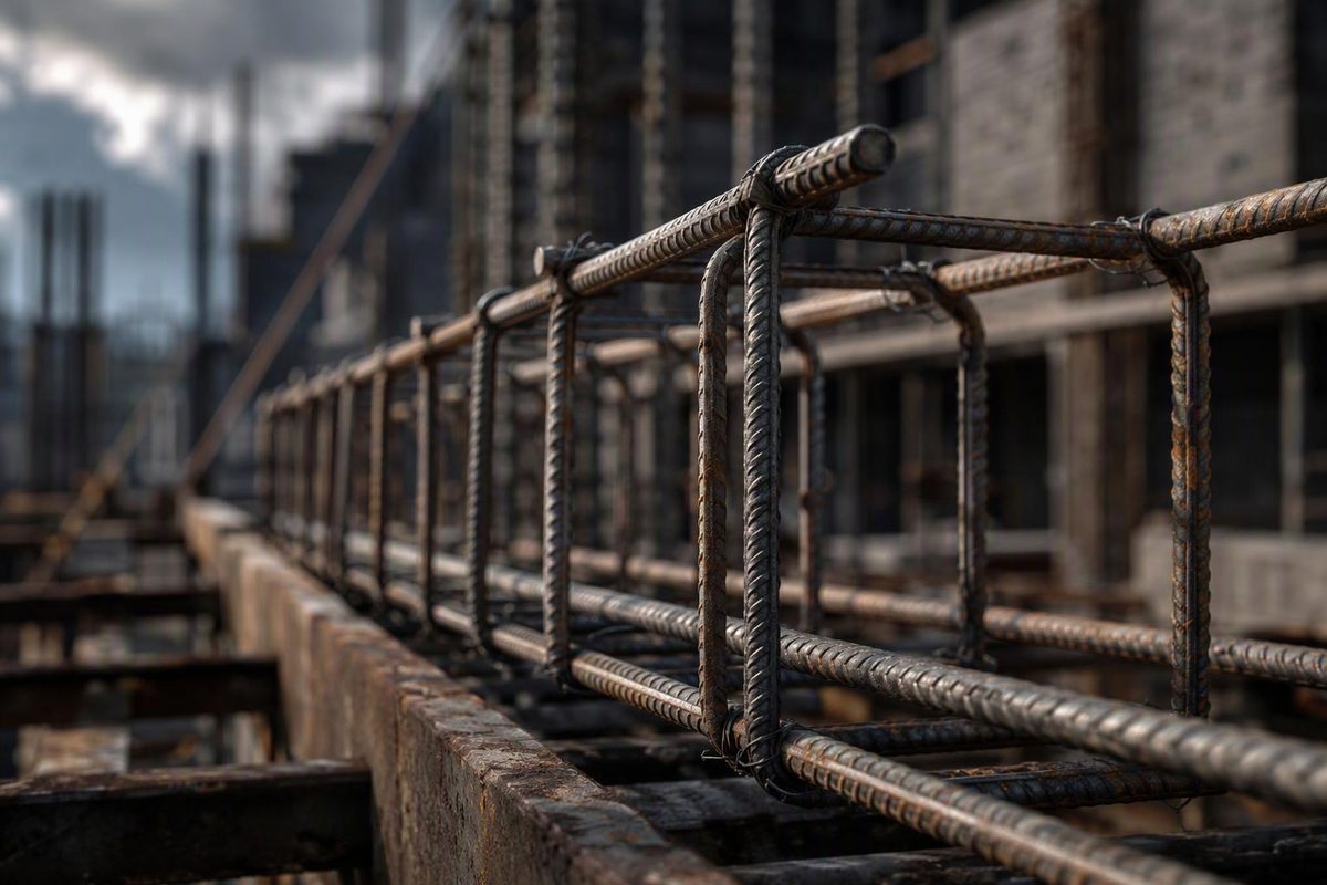
Rebar stirrups are reinforcing bars bent to run across a concrete beam’s longitudinal reinforcement, commonly as repeated U-shaped or rectangular units. They are structural reinforcement, not simply brackets holding a cage together. Their shape, anchorage and spacing determine how they contribute to shear resistance and, where designed for it, torsion resistance or confinement.
The American Concrete Institute’s terminology defines a stirrup by its orientation across, or at an acute angle to, the longitudinal reinforcement in a flexural member. Similar loops around a column’s longitudinal bars are generally called ties. The distinction helps when reading details: similar-looking steel can have different design requirements.
What stirrups do inside concrete
Longitudinal bars run along the beam and provide reinforcement for bending. Stirrup legs cross the beam’s depth. In a simplified shear-resisting model, concrete carries diagonal compression while transverse steel carries tension. This division of roles appears in the truss models discussed in Oregon DOT’s reinforced-concrete shear research. Stirrups provide shear reinforcement; they do not make the beam crack-proof.
Closed transverse reinforcement can do additional work. In earthquake-resistant frame regions, hoops confine the concrete core, restrain longitudinal bars against buckling and resist shear. These functions become important when loading reverses and reinforcement yields. NIST’s 2016 guide to reinforced-concrete special moment frames explains these mechanisms; its numerical provisions reference ACI 318-14, so it is not a substitute for the code governing a current project.
Torsion—twisting about the member’s length—requires a different load path from ordinary beam shear. Where torsion reinforcement is required, closed transverse reinforcement works with longitudinal reinforcement distributed around the perimeter. A U-shaped stirrup cannot simply replace a specified torsion loop. A 2007 technical article by Portland Cement Association engineers explains why closure and anchorage matter, including the loss of effectiveness of some details when concrete cover spalls. Its code calculations are historical, not current-project design guidance.
Tie wire has a separate purpose: keeping reinforcement in position during assembly and concrete placement. It does not replace designed stirrups or their anchorage. CRSI’s placing guidance distinguishes bar placement, supports and wire tying.
Shapes are not interchangeable
| Detail | What to recognize | What to verify |
|---|---|---|
| Open or U-shaped stirrup | Two legs joined across one side of the section, with specified end anchorage | Hook location and whether the design requires a closing component |
| Closed rectangular stirrup or hoop | Reinforcement enclosing the section | Closure, hook geometry and which longitudinal bars it engages |
| Multi-piece hoop | A designed assembly of stirrups and crossties or multiple hoops | Every component, its orientation and its anchorage |
| Multiple-leg arrangement | Additional transverse legs across the member width | Leg count and positions, not just the outside loop |
A hoop need not be a single uninterrupted piece. NIST illustrates engineered assemblies using stirrups and crossties, which can allow top longitudinal bars to be installed before the closing pieces. That is a specific detailed assembly, not permission to close any U-bar with wire or an improvised overlap. See the guide’s beam transverse-reinforcement details.
Hooks are part of anchorage. Check the bend diameter, angle, straight extension and orientation shown in the detail. Do not assume a 90° hook and a 135° hook are equivalent, or that every stirrup requires the same hook. In the seismic details discussed by NIST, a 135° hook remains anchored in the core when cover spalls, whereas a 90° hook can bend outward and lose effectiveness.
Read the section, elevation and schedule together
A beam section shows what surrounds the longitudinal bars. The elevation shows where each transverse unit goes along the beam. The bar schedule identifies the fabricated pieces. Read them together rather than treating one view as the complete instruction.
For example, an illustrative callout S1 @ 150 mm c/c means the unit identified as S1 repeats at 150 mm center-to-center in the indicated zone. S1 is a mark to resolve against the schedule, not necessarily a bar diameter. The number here demonstrates notation only; it is not a recommended spacing.
Before ordering or placing stirrups, reconcile:
- Member identification: beam mark, section dimensions and detail references.
- Bar specification: size, grade and any specified coating.
- Shape: dimensions, leg count, bends, hooks and separate closing pieces.
- Placement: first-unit offset, spacing-zone boundaries and special details at joints or splices.
- Cover and fit: clearance to forms, adjacent reinforcement and embeds.
Center-to-center spacing is not the clear gap between bars. Likewise, concrete cover is the clear distance from the concrete surface to the outer surface of the outermost reinforcement—usually the stirrup where it surrounds the main bars—not to the longitudinal-bar centerline. These distinctions are explained in Caltrans’ June 2025 reinforcement manual. Its contract-specific minimum dimensions should not be transferred to unrelated buildings.
Spacing is a design output, not a DIY rule
Spacing reflects shear demand, member geometry, reinforcement strength and applicable detailing requirements. Confinement or torsion may govern even where an ordinary shear check would suggest otherwise. A tighter zone near a support cannot be extended, shortened or averaged across the span without checking the design.
For architects, the coordination question is whether the required cage fits and leaves room to place and consolidate concrete. Hooks, overlapping reinforcement, couplers and embeds can crowd a narrow beam or joint. NIST’s constructability guidance emphasizes coordinating reinforcement fit and concrete placement, rather than discovering conflicts during installation.
If a duct, sleeve or bar clash interrupts a stirrup, obtain the structural engineer’s revised detail before cutting, relocating or substituting it. Coordinate the complete rebar cage, not just its outer dimensions—and verify stirrup marks, counts, spacing zones, hooks and cover while the reinforcement remains accessible for inspection.