
How Reinforcement Cages Work—from the Bar Schedule to the Concrete Pour
It must provide the reinforcement required by the design, remain stable during handling and leave enough room for concrete to surround the steel.
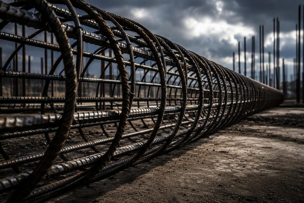
A rebar cage has to solve three connected problems. It must provide the reinforcement required by the structural design, remain stable during fabrication and handling, and leave enough room for concrete to pass through the assembly and surround the steel.
Satisfying one objective does not guarantee the others. A cage can contain the scheduled steel yet distort when lifted. It can arrive with the correct shape but the wrong bar grade or splice arrangement. It can satisfy structural calculations while being too congested for reliable concrete placement.
The cage should therefore be treated as an integrated assembly. Permanent reinforcement, temporary bracing, concrete-placement method, splices, accessories, supports, lifting provisions, inspection criteria, and delivery sequence must be coordinated. This article is a nonprescriptive overview, not a design, lifting, welding, or acceptance procedure. Project requirements must come from current drawings, specifications, responsible professionals, qualified lifting and safety personnel, and the applicable governing documents.
What a rebar cage is—and where it is used
A typical cylindrical rebar cage consists of longitudinal reinforcing bars distributed around a perimeter and connected by transverse reinforcement. Depending on the design, that transverse steel may consist of individual ties, closed hoops, a continuous spiral, clamps, or appropriately specified welded connections.
Cages are used in drilled shafts, piers, columns, caissons, foundations, footings, and concrete form-tube applications. The same term can therefore describe very different assemblies: a compact cage handled around a small project is not equivalent to a long drilled-shaft cage requiring transport planning, engineered lifting provisions, substantial stiffening, and a crane.
The longitudinal and transverse reinforcement form the structural core, but a cage may also include:
- Sizing hoops that establish diameter or shape
- Centering guides or centralizers that help maintain position and cover
- Stiffeners or bracing rings that preserve geometry during fabrication and handling
- Pickup devices or lifting provisions
- Supports or spacers that maintain elevation and clearance
- Crosshole sonic logging pipes, where the project requires them
- Splices, couplers, embeds, and connection bars
- Identification tags that coordinate fabrication and placement
Technical material attributed to an FHWA drilled-shaft manual describes a typical cage as longitudinal bars around a cylinder, with transverse steel connected by ties, clamps, or, in special cases, welds. It also identifies sizing hoops, centering guides, stiffeners, and pickup devices as possible components. Pile Buck reproduces the drilled-shaft chapter containing this description.
Textual anatomy key
A cage drawing or fabrication model should make the following elements distinguishable:
- Longitudinal bars
- Ties, hoops, or spiral reinforcement
- Lap or mechanical splices
- Sizing hoops or internal rings
- Centralizers or guides
- Temporary stiffeners
- Approved pickup points or lifting attachments
- Optional logging pipes
- Intended concrete cover
- The smallest usable concrete-flow opening
The drawing should also distinguish permanent structural reinforcement from parts provided primarily for fabrication, alignment, handling, or testing.
Stock cage versus engineered drilled-shaft cage
A stock cage uses a recurring layout selected by a supplier for common commercial demand. One seller, for example, lists a cage with a 12-inch diameter, 5-foot height, four #4 longitudinal bars, and six #3 ties at 12 inches on center. Those figures describe that specific retail product; they are not a recommended detail for a pier, shaft, foundation, or form tube. The Bolsinger Rebar product listing provides the dimensions, reinforcement, grade, configurations, and storefront price.
A large drilled-shaft cage may instead be fabricated for a single shaft designation. It can require several bar sizes, variable transverse spacing, staggered splices, mechanical connectors, tremie access, logging pipes, centralizers, lifting hardware, and temporary bracing.
Labels such as “pier cage” or “drilled-shaft cage” do not establish suitability. Cage diameter, length, reinforcement, cover, anchorage, and splices can depend on:
- Structural loads and load combinations
- Soil, rock, groundwater, and foundation conditions
- Element geometry
- Development and anchorage requirements
- Concrete properties and maximum aggregate size
- Dry, pumped, dropped, or tremie placement
- Exposure and corrosion-protection requirements
- Confinement or ductility demands
- Construction tolerances
- Approved drawings, specifications, and governing requirements
A catalog product may be useful when it matches an engineered schedule. Its product name and physical fit are not enough to demonstrate that match.
The structural roles of longitudinal and transverse reinforcement
The two principal reinforcement directions perform different functions.
Longitudinal reinforcement runs generally parallel to the cage axis. In a drilled shaft, it principally resists bending and the associated tensile stresses. Its area, grade, bar size, distribution, length, development, and connections are structural design decisions.
Transverse reinforcement wraps around or crosses the longitudinal bars. Depending on the structural system and detail, it can:
- Hold longitudinal bars in their required positions
- Contribute to shear resistance
- Confine the concrete core
- Support compressive or flexural behavior
- Restrain longitudinal bars
- Contribute to post-yield ductility
- Help preserve geometry before the concrete hardens
Even distribution of longitudinal bars commonly produces a more symmetrical cylindrical cage than concentrating bars on one side. That may be useful where bending direction can vary, but even spacing is not a substitute for structural calculation. The number and arrangement of bars must follow the approved design.
Tie wire is not the transverse reinforcement
Tie wire at bar intersections generally serves a construction function: it keeps the designed reinforcement in position while the cage is assembled, moved, and surrounded by concrete. The wire is not ordinarily the primary designed reinforcement.
The phrase “tied cage” can consequently refer to two different things:
- The structural ties, hoops, or spiral shown in the bar schedule
- The smaller wire connections fastening those members to the longitudinal bars
Additional tie wire does not compensate for missing structural ties. Conversely, a complete set of structural hoops does not automatically make a cage suitable for handling if its connections and temporary bracing cannot withstand the planned movement.
The necessary tying pattern depends on cage orientation, weight, handling sequence, and project requirements. A horizontal mat that receives limited handling does not face the same demands as a long cage that will be rolled, transported, raised from horizontal, and lowered into an excavation. The approved fabrication and handling procedures should determine the connection pattern rather than a universal instruction to tie every intersection or every other intersection.
Confinement and concrete flow can conflict
Closer transverse spacing can be structurally useful where greater confinement or ductility is required. It also reduces the vertical opening through the cage. Reinforcement that improves confinement may therefore make it harder for concrete and aggregate to pass into the cover zone.
Splice regions create a similar conflict. Overlapping longitudinal bars can make one short portion of the cage much denser than the rest. Couplers, bundles, internal braces, logging pipes, and embeds further reduce available space.
These conflicts belong in design and detailing coordination. They should not be addressed by moving bars, cutting ties, changing splices, or altering the concrete mixture without documented authorization.
Permanent steel versus temporary handling elements
Longitudinal bars and scheduled transverse reinforcement remain embedded and perform the designed structural work. Stiffeners, temporary cross-bracing, lifting frames, spreader arrangements, and some pickup devices may exist principally for fabrication or handling.
Their purpose, connections, effect on concrete flow, and intended disposition should be documented. Calling an element temporary does not make its obstruction or load path unimportant.
How cage geometry is coordinated with concrete placement
A reinforcement layout is not constructible merely because every scheduled bar fits inside the concrete outline. Concrete must pass through the cage, move around splices and accessories, reach the space outside the longitudinal bars, and fill the cover zone without harmful blockage or segregation.
The controlling dimension is often not nominal cage diameter. It is the smallest usable opening after reinforcement, connectors, pipes, and temporary components are included.
Factors that reduce this opening include:
- Larger or more numerous longitudinal bars
- Tighter hoop or spiral pitch
- Lap zones with overlapping bars
- Couplers larger than the connected bars
- Bundled bars
- Multiple reinforcement layers
- Concentric cages
- Stiffeners or internal bracing
- Logging pipes, embeds, and conduits
- Limited space for a tremie or pump line
The approved concrete mixture also matters. An opening that appears generous relative to cement paste may still restrict coarse aggregate. Placement method changes the required flow path: concrete placed under assured dry conditions does not necessarily move through a cage in the same way as tremie-placed concrete.
Contextual spacing guidance—not a universal rule
The reproduced drilled-shaft guidance reports several aggregate-based approaches. It cites research suggesting clear spacing of approximately eight times the largest coarse-aggregate size for tremie-placed concrete. It also says many agencies use openings of at least 5 inches in both directions and at least ten times the largest aggregate size, while approximately five times the largest aggregate size may be considered for assured dry placement. These are reported practices and research findings, not universal code requirements. The drilled-shaft chapter explains the figures and their placement context.
Those values should not be transferred automatically to another structural element, concrete mixture, specification, or jurisdiction. The applicable project documents and responsible design and concrete-placement teams govern.
Tightly pitched spirals can be difficult because concrete may need to move laterally through them. Concentric cages introduce a second barrier and a narrow region between reinforcement layers. Concrete can enter the cage interior yet still fail to move uniformly through both layers toward the excavation wall, increasing the risk of incomplete filling or defective concrete.
Possible design responses to congestion
When a preliminary layout is too congested, the design team may evaluate alternatives such as:
- Bundling selected longitudinal bars
- Using higher-strength reinforcement where permitted
- Replacing lap splices with approved mechanical connectors
- Staggering or relocating splices
- Revising transverse-reinforcement details
- Enlarging the shaft or concrete element
- Reconsidering concentric reinforcement layers
- Coordinating logging-pipe and accessory locations
- Revising the mixture or placement plan within project requirements
Each alternative has consequences. Bundling affects development. Couplers introduce system-specific installation and inspection requirements. These are design alternatives, not field fixes.
An illustrative concrete-flow review
A non-design constructability review can ask:
- What is the placement method? Identify whether placement will occur under assured dry conditions, by pump, by drop, or by tremie.
- What is the approved maximum aggregate size? Use the accepted mixture rather than an early concept.
- Where are the smallest horizontal openings? Include bars, bundles, couplers, pipes, and accessories.
- Where are the smallest vertical openings? Include hoops, ties, spiral pitch, and local changes near cage ends.
- What happens at every splice? Model actual lap and connector dimensions.
- Can concrete reach the cover zone? Check the path outside the longitudinal reinforcement.
- Is placement access preserved? Where applicable, account for tremie or pump-line access and withdrawal.
- Are temporary components included? Do not assess permanent reinforcement while ignoring stiffeners and braces.
- Were conflicts resolved before fabrication? Record accepted changes in controlled drawings.
- Was the review repeated after substitutions? A different coupler, bar, pipe, or mixture can change the result.
Tied, welded, spiral, ring-braced, stock, custom, or kit: choosing a fabrication approach
Fabrication involves two separate questions: how the members will be connected and where the assembly will occur.
A cage can be field-tied or shop-tied. It can contain specified welds without being entirely shop-prefabricated. A supplier may deliver a complete cage, transport-sized sections, or a kit of cut and bent components. The term “prefabricated” should therefore be defined in each proposal.
Main fabrication and purchasing formats
Field-built cages are assembled at or near installation. Components travel compactly, and field assembly can accommodate restricted delivery routes. The tradeoffs include field labor, weather exposure, laydown demand, and the need to control geometry under site conditions.
Shop-prefabricated cages arrive substantially complete. Shop jigs and repeatable processes can support dimensional control, but complete cages occupy considerable transport volume and may require sequenced delivery, storage, and crane handling.
Cut-and-bent kits occupy the middle ground. The supplier cuts, bends, groups, and labels reinforcement for an assembly, while the contractor completes the cage. This can reduce field measuring and cutting without shipping a full three-dimensional cage. Vendor material distinguishes such kits from complete cages and describes stock products as established layouts and custom products as responses to nonstandard requirements. Bolsinger Rebar explains these purchasing formats in its prefabrication overview.
Stock cages use recurring dimensions and reinforcement arrangements. Their benefit is repeatability when the accepted design matches the product.
Custom cages follow project-specific dimensions, materials, reinforcement, and accessories. They can accommodate unusual geometry or repeated project details, but reliable fabrication depends on coordinated, sufficiently mature information.
Commercial catalogs list both circular and square prefabricated cages in steel and glass-fiber-reinforced polymer, or GFRP. That availability does not make the materials structurally interchangeable; each requires project-specific design and approval. The Rebar.Shop catalog illustrates the different listed shapes and materials.
Tied versus welded assemblies
Ties allow bars to be positioned and secured without creating a welded metallurgical connection. Tie type and frequency depend on orientation, bar weight, handling, and project requirements.
Welding can produce a rigid assembly, but “welded cage” is not automatically a higher-quality category. It raises questions about reinforcement specification, chemical composition, connection design, heat effects, procedures, qualifications, inspection, and repairs. A cage should not be tack-welded simply because wire ties are inconvenient.
Spirals and hoops are transverse-reinforcement arrangements rather than competing connection methods. A spiral is generally continuous; hoops or ties are discrete pieces placed at specified intervals. Either arrangement must be connected to the longitudinal steel as the approved details require.
Engineered rings may locate longitudinal bars, support geometry, or incorporate positions for logging pipes. Claims that proprietary systems guarantee exact roundness, extremely fine alignment, or safe lifting remain vendor assertions unless supported by applicable capacities, tests, connection details, and project acceptance documentation.
Qualitative fabrication-format comparison
The following table shows planning tendencies, not guaranteed labor, schedule, or performance outcomes.
| Format | Field labor tendency | Shop lead-time tendency | Repetition | Transport size | Crane implications | Dimensional control | Welding | Customization |
|---|---|---|---|---|---|---|---|---|
| Field-tied complete cage | Higher | Lower to moderate | Moderate | Components arrive compactly | Depends on completed cage | Depends on jig, crew, and checks | Avoidable unless specified | High |
| Shop-prefabricated cage | Lower at site assembly | Moderate to higher | Strong potential | Bulky | Often significant | Can benefit from shop jigs | Detail-dependent | High |
| Prefabricated sections | Moderate | Moderate to higher | Good | More manageable than a full cage | Needed for sections and assembly | Depends on controlled interfaces | Project-dependent | High |
| Cut-and-bent kit | Moderate to higher | Moderate | Good | Compact relative to a cage | Depends on final assembly | Depends on field setup | Usually avoidable unless specified | High |
| Stock cage | Lower | Availability-dependent | Best for repeated accepted details | Fixed by product | Size-dependent | Based on recurring supplier layout | Product-dependent | Low |
| Custom cage | Lower to moderate on site | Usually higher than stock | Strong for repeated details | Project-specific | Often significant | Can be specified and checked | Project-dependent | Very high |
No format guarantees lower installed cost or faster completion. Results depend on repetition, design stability, supplier capacity, transport, site readiness, labor, lifting access, and change timing.
Jigs and alignment
A reusable jig can locate longitudinal bars at consistent intervals while transverse reinforcement is installed. It is a fabrication aid, not a reinforcement design.
Informal plastic-pipe jigs may demonstrate the value of a repeatable template, but they do not establish cage diameter, cover, reinforcement, or tolerances. Welded wire mesh should likewise not replace scheduled hoops, ties, or spirals based on a do-it-yourself example. Substitutions require engineering review and documented approval.
Steel grade, welding, coatings, and material selection
Material identity should be confirmed before bars are incorporated into the cage. Visual similarity does not establish grade, weldability, coating, or compliance with the bar schedule.
The reproduced drilled-shaft guidance discusses reinforcement conforming to AASHTO M 31, corresponding to ASTM A615, in Grades 40 and 60. It also identifies ASTM A706 as an option that may be specified when welding is intended. These are standards-sensitive references from the supplied technical material, not a statement that every project accepts those specifications or grades. The cited drilled-shaft trade guide summarizes those material references.
Welding needs more than a weldable designation
A weldable reinforcement designation does not eliminate the need for:
- Approved connection details
- An appropriate welding procedure
- Qualified personnel
- Confirmation of material and chemical composition
- Supervision and quality control
- Required inspection and testing
- Repair and rejection criteria
- Coating protection or repair where applicable
CRSI recommends against routine field manual-arc welding and against connecting crossbars with small tack welds, which it associates with brittle failure of rebar assemblies. It also states that welded splices require engineering, inspection, supervision, and quality control beyond a generic instruction to follow a welding code. CRSI’s bar-splicing guidance describes these cautions.
A proposal to weld a cage merely “for rigidity” should therefore be referred to the responsible design and quality-control parties.
Bond, cleanliness, coatings, and alternative materials
Deformed bars promote mechanical bond with concrete. Before placement, reinforcement should be free of excessive rust, soil, oil, or other contaminants that could impair bond. Applicable project criteria should determine whether cleaning, repair, or rejection is required.
Galvanized or epoxy-coated reinforcement may be specified where exposure warrants it. Fabrication and handling can damage coatings, so the project documents should define permitted operations and the criteria for inspection and repair.
Its use requires its own project-specific design, specifications, fabrication approach, and handling requirements.
Material-confirmation checklist
Before fabrication, use the approved project documents to confirm:
- Bar size and quantity
- Material specification and grade
- Bar type
- Coating system, if any
- Weldability requirements
- Required material documentation
- Traceability requirements
- Approved welding details and procedures
- Coupler compatibility
- Permitted cutting and bending methods
- Coating-damage criteria
- Cleaning and acceptance requirements
- Approved substitutions
No material should be described categorically as the most durable, economical, or compliant option. Those judgments depend on design, exposure, supply, construction, inspection, and project criteria.
Splices and congestion in long cages
Long cages may exceed available bar lengths, practical transport dimensions, or lifting limits. They may therefore use lap splices, mechanical connectors, welded splices, or cage sections connected after the lower section has entered the borehole.
Splice locations and lap lengths are structural information. They should be shown by the architect or engineer on the structural or placing drawings.
Lap splices
A lap splice transfers force through overlapping bars and the surrounding concrete. Required length depends on concrete strength and type, reinforcement grade and size, bar spacing, cover, transverse reinforcement, and other design conditions.
Contact laps are often easier to wire and secure against movement than widely separated non-contact laps. That practical advantage does not establish the required lap length or mean every splice must be in contact.
The principal cage tradeoff is congestion. Every lap introduces additional steel, potentially reducing horizontal and vertical concrete-flow openings. Concentrating many laps at one elevation can make a short section substantially denser.
A drilled-shaft trade article states that, when staggering is required, no more than 50 percent of longitudinal splices should occur at one level. That is contextual secondary-source guidance, not a universal rule; the engineered splice schedule governs. Pile Buck’s drilled-shaft guide reports the 50 percent statement.
Mechanical connectors
Mechanical connectors can reduce the length of overlapping steel and relieve congestion. They may also require proprietary hardware, prepared bar ends, torque control, grout, hydraulic equipment, or other system-specific procedures.
Inspection must address the selected system rather than merely confirming that a coupler is present. Applicable drawings, manufacturer instructions, and project criteria should define the installation records and checks required.
The interfaces must be coordinated so connections can be completed without forcing the cage out of shape.
Welded and in-borehole splices
Welded splices require compatible steel, approved details, and substantially more quality-control attention than a generic welding note.
An in-borehole splice can address transport or lifting constraints by lowering one cage section and connecting another above it. The operational tradeoff is that work over an open shaft can delay concrete placement, restrict access, and increase alignment and inspection pressure. The installation plan should account for those effects.
Qualitative splice comparison
| Splice method | Congestion | Equipment | Inspection focus | Installation setting | Principal limitation |
|---|---|---|---|---|---|
| Contact lap | High in overlap zone | Tying tools | Length, location, security, bar position | Shop or field | Added steel can restrict concrete flow |
| Non-contact lap | High across a broader width | Tying and positioning tools | Length, separation, security, geometry | Shop or field | More difficult to secure; separation is design-dependent |
| Mechanical connector | Often less than a lap | System-specific tools | Preparation, engagement, and required system controls | Shop, field, or sectional assembly | Cost, proprietary procedures, and alignment |
| Welded splice | Potentially compact | Welding and inspection equipment | Compatibility, procedure, qualifications, weld quality | As approved for the project | Heat effects, access, records, and inspection burden |
| In-borehole sectional splice | Connection-dependent | Lifting equipment and splice tools | Alignment, completed connection, access, timing | Above or partly within the borehole | Can delay concreting and complicate quality control |
The appropriate splice must satisfy force transfer, concrete flow, fabrication, installation, and inspection requirements together.
Transporting, lifting, lowering, and supporting the cage
A cage that will be stable after concrete hardens may be flexible before placement. Permanent reinforcement is selected for the completed structural element and may not, by itself, resist the temporary bending, torsion, or concentrated loads created during transport and lifting.
Large or long cages may need sizing hoops, stiffeners, engineered bracing rings, pickup devices, or other strengthening to prevent unacceptable distortion.
Lifting and temporary stability should be treated as a separate coordination package prepared and executed by the qualified parties designated for the project. The following are coordination questions, not a rigging procedure:
- Are cage and section weights, dimensions, and relevant balance information established?
- Have transport restrictions and the delivery route been reviewed?
- Are site access, laydown conditions, and delivery sequence compatible with the cage?
- Has crane access and the proposed lifting operation been evaluated by the responsible qualified personnel?
- Are pickup points, lifting attachments, spreaders, and temporary bracing defined where required?
- Is the intended movement—such as lifting vertically, raising from horizontal, or assembling sections—clearly described?
- Have stiffeners and bracing been checked before movement?
- Is there a plan to protect reinforcement and coatings from dragging and impact?
- Can alignment and cover be maintained during lowering?
- Is the intended disposition of temporary bracing documented?
- Can the installed cage be maintained in its accepted position during concrete placement?
These questions do not replace the project lift plan, applicable safety requirements, equipment instructions, or the authority of qualified lifting and safety personnel.
Treat performance claims cautiously
Proprietary rings and bracing systems may locate bars, maintain shape, or coordinate logging pipes. Supplier claims about exact roundness, alignment measured in thousandths of an inch, safe lifting, or superior handling should not be treated as verified project performance without applicable design limits, connections, test evidence, tolerances, and acceptance documentation.
Dimensional control and lifting capacity are separate questions. A ring may position bars accurately without being adequate for the loads imposed by a particular cage weight, pickup arrangement, or orientation.
The logistical cost of prefabrication
Shop prefabrication shifts some work away from the site but does not eliminate it. It may add:
- Shop-drawing and release coordination
- Fabrication lead time
- Bulky freight
- Delivery appointments
- Storage and protection
- Handling equipment
- Crane picks
- Site-access planning
- Change-management exposure
A complete cage may suit repetitive work with stable drawings and suitable lifting access. A kit or sectional cage may be more practical where transport, storage, or site constraints make a complete assembly difficult.
Inspection and procurement: what to verify before the pour
Inspection is easier to manage in stages. The following lists are coordination prompts; actual acceptance criteria, tolerances, hold points, and inspector authority must come from the project documents and governing requirements.
Fabrication inspection
Compare the assembly with the current approved documents, including:
- Overall length, diameter, shape, and section dimensions
- Longitudinal bar size, quantity, grade, and spacing
- Tie, hoop, or spiral size and spacing
- Reinforcement orientation and termination
- Splice type, location, staggering, and required length
- Mechanical-connector identification and installation
- Alignment and specified fabrication tolerances
- Tie integrity and required connection pattern
- Specified weld locations and required records
- Coating type and visible damage
- Sizing hoops, stiffeners, and accessories
- Required logging pipes, guides, centralizers, embeds, and supports
- Identification tags and placement sequence
- Material documentation
- Approved revisions and substitutions
Dimensional conformity alone does not establish structural acceptance. A cage can be straight and round while containing the wrong grade, bar size, splice, or coating.
Pre-lift inspection
Before movement, the responsible project parties should confirm the items assigned by the approved lifting and safety documentation, which may include:
- Cage or section weight
- Required stiffeners and bracing
- Designated pickup points
- Loose, missing, bent, or damaged reinforcement
- Condition of ties, clamps, and specified welds
- Coating damage and required repairs
- Approved lifting arrangement and equipment
- Planned travel and receiving conditions
- Readiness of the excavation or placement area
This review should occur early enough for deficiencies to be resolved before scheduled lifting operations begin.
Final pre-pour inspection
Once the cage is in place, check the project-defined requirements for:
- Horizontal position and elevation
- Verticality where applicable
- Concrete cover
- Centralizers, chairs, spacers, and supports
- Stability against movement during placement
- Reinforcement cleanliness
- Clear concrete-flow openings
- Tremie or pump-line access where applicable
- Completed and accepted splices
- Embeds, dowels, anchors, and connections
- Logging pipes where required
- Disposition of temporary bracing
- Form, excavation, or borehole readiness
- Approved concrete mixture and placement sequence
- Resolution of inspection comments and nonconformances
Tie wire and supports have different functions: ties connect bars to one another, while chairs, centralizers, and related supports maintain position relative to the concrete boundary. Both must remain effective through placement as required by the project.
Supplier request-for-quote checklist
A request for quote should define what the supplier is pricing:
- Approved or clearly identified bid drawings
- Cage marks and quantities
- Overall dimensions
- Bar schedule
- Material specification and grade
- Coating requirements
- Tie, hoop, or spiral details
- Splice system
- Welding requirements
- Fabrication tolerances
- Accessories, pipes, and embeds
- Cage and section weights where required
- Temporary bracing and lifting provisions
- Responsibility for lifting-attachment design
- Labeling and tagging
- Required submittals and shop drawings
- Material, weld, coating, and coupler records
- Inspection hold points
- Delivery sequence and packaging
- Freight, unloading, taxes, and storage assumptions
- Lead time and release dates
- Exclusions
- Revision and change-management process
Design responsibility should be explicit. A supplier’s statement that a cage is “built to customer specifications” does not establish that the supplier engineered the reinforcement or lifting system.
Compare installed cost, not unit price
A unit price excludes many costs that affect the procurement decision:
- Shop fabrication and field assembly
- Freight, unloading, and taxes
- Storage and protection
- Lifting equipment and crane time
- Supports and centralizers
- Couplers and installation tools
- Temporary bracing
- Engineering and shop drawings
- Inspection and documentation
- Coating repairs
- Rework and rejected material
- Schedule and change exposure
In storefront information reviewed on August 20, 2026, Bolsinger Rebar listed its 12-inch-diameter, 5-foot steel cage at $59.99 excluding shipping. Rebar.Shop listed differently configured 5-foot by 12-inch circular steel and GFRP cages at $126 and $176. These volatile listings do not establish equivalent reinforcement, materials, availability, location, freight, taxes, or included services, so they cannot support a like-for-like value conclusion. The Rebar.Shop catalog displays the referenced configurations and storefront prices.
The useful comparison is the cost of delivering an accepted cage to its required final position, ready for concrete—not merely the advertised price at the supplier’s door.
Discrepancies, damage, unapproved substitutions, missing records, and out-of-tolerance conditions should be referred to the parties identified by the project’s quality process. Cutting bars, moving ties, adding tack welds, substituting couplers, or forcing a distorted cage into place can change reinforcement position, concrete flow, cover, and acceptance. Work affecting the cage should not proceed until the required documented resolution has been obtained.
Frequently asked questions
Can I use a stock rebar cage for a pier or sonotube?
Only when the stock cage matches the engineered project requirements and is accepted through the required review process. Similar diameter or a seller’s application label does not establish suitability.
Check length, bar size and quantity, transverse reinforcement, material grade, coating, cover, anchorage, splices, loads, exposure, concrete mixture, placement method, and foundation conditions against the current drawings and specifications.
Is a welded rebar cage better than a tied cage?
Not universally. Tied construction permits positioning without welded connections, while a properly designed welded assembly may provide fabrication rigidity. The appropriate approach depends on reinforcement specification, connection details, handling, fabrication conditions, inspection resources, and project requirements.
A weldable bar designation does not make arbitrary field welding acceptable. Welding still requires approved details, compatible material, procedures, qualified work, supervision, quality control, and inspection.
How much clear spacing does a rebar cage need for concrete to pass through?
There is no single multiplier for every cage. Required openings depend on aggregate size, concrete properties, placement method, reinforcement, couplers, splices, accessories, and project specifications.
A drilled-shaft trade source reports contextual guidance of approximately five times the largest aggregate size for assured dry placement, eight times for tremie placement in cited research, and ten times plus a 5-inch minimum opening in practices attributed to many agencies. These are secondary-source recommendations rather than universal requirements. Evaluate the smallest actual horizontal and vertical openings under the current project criteria.
When does a prefabricated rebar cage make sense?
Prefabrication is most promising where layouts repeat, drawings can be released in time, supplier capacity is suitable, and transport and lifting access are practical. It can shift assembly away from the site and allow fabrication to proceed while other work continues.
Its value decreases when designs are changing, cages are difficult to transport, storage is limited, site access is poor, or delivery sequencing is uncertain. Kits or cage sections may provide a middle option. Compare installed cost and schedule exposure rather than assuming prefabrication is automatically faster or cheaper.
What should be checked before concrete is placed around a rebar cage?
Verify the cage against the current approved drawings and project criteria. Typical coordination subjects include final position, elevation, verticality where applicable, cover, supports, centralizers, reinforcement spacing, completed splices, cleanliness, accessories, embeds, and stability.
Also review the concrete path through the assembly, including the smallest openings, splice congestion, placement-line access, temporary components, and the cover region outside the longitudinal bars. Damage, undocumented changes, missing records, or nonconforming conditions should be resolved through the project’s approved quality process before placement.
A successful rebar cage is not simply a bundle of correctly sized bars. Permanent reinforcement, temporary handling stability, concrete-flow openings, splices, supports, lifting provisions, and installation sequence must function as a coordinated system. Use these anatomy notes, comparisons, and checklists to frame the right questions, while relying on current project documents and responsible professionals for every design, safety, material, and acceptance decision.