
ICF Walls: What Changes on the Drawings
How ICF walls combine reinforced concrete and continuous foam—and how to detail thickness, openings, attachments, waterproofing and placement.
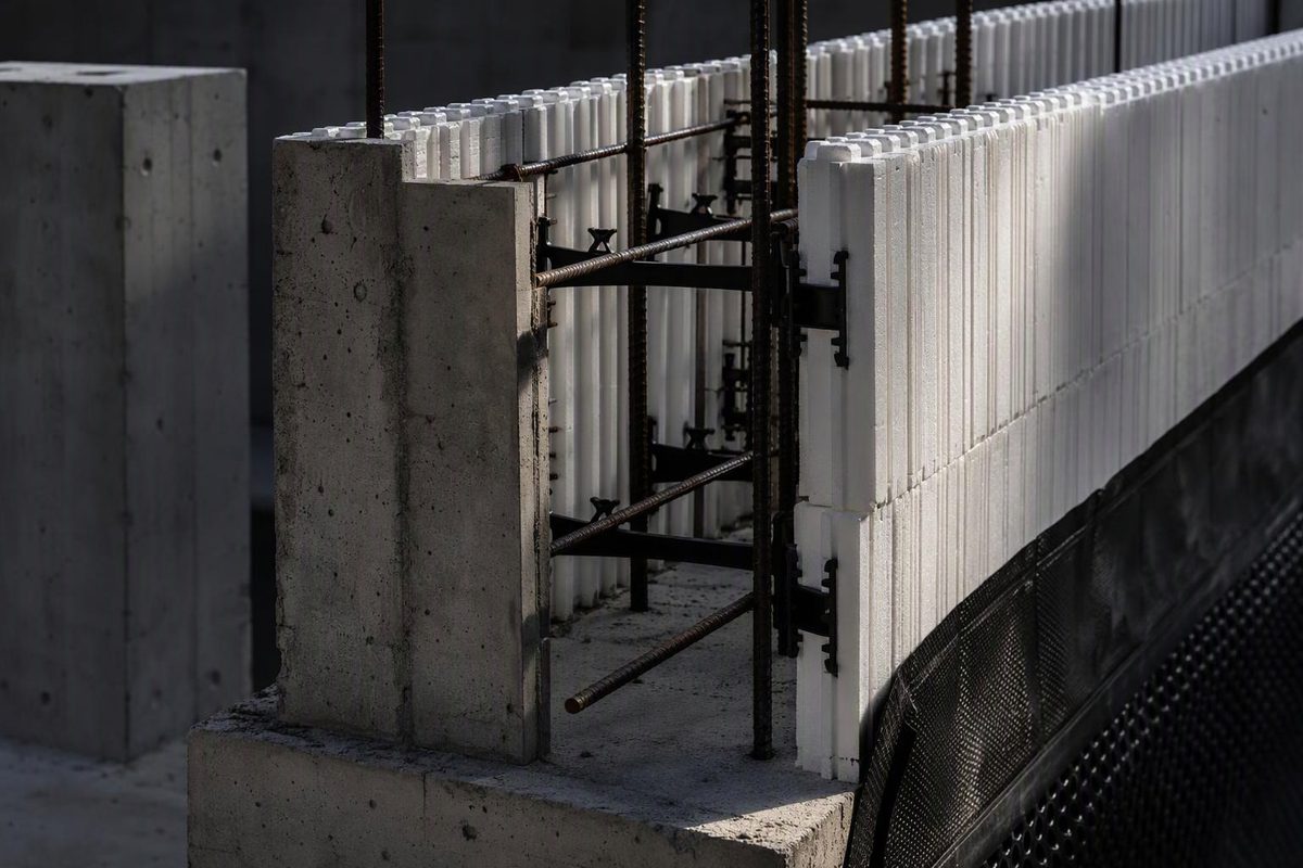
ICF walls combine permanent insulating formwork with reinforced concrete. The foam blocks or panels establish the wall geometry and remain after the pour; reinforcing steel and the concrete core carry the structural loads. Ties or webs connect the form faces and, in many systems, provide fastening flanges for finishes.
“Insulated concrete forms” is common usage, but codes and technical standards generally call them insulating concrete forms (ICFs). ACI describes the common wall form as two low-absorptive foam layers held together by cross-ties, with reinforcement and concrete placed in the cavity. It also emphasizes that ICF systems are proprietary and generally not interchangeable (ACI PRC-560-22).
What is inside an ICF wall?
From exterior to interior, a typical above-grade flat-wall assembly is:
- Exterior cladding or coating
- Drainage, flashing and water-control components required by that cladding
- Outer expanded-polystyrene (EPS) form face
- Plastic or metal cross-ties spanning the form
- Cast-in-place reinforced-concrete core
- Inner EPS form face
- A code-compliant thermal barrier and interior finish
The webs often hold horizontal reinforcing bars during construction and provide fastening flanges near each face. Their capacities and spacing are product-specific. The 2024 IRC requires rigid foam stay-in-place forms to be protected on the interior and exterior; where gypsum board protects the interior foam, it must be mechanically fastened, although adhesive may supplement the fasteners (2024 IRC Section R608).
Typical dimensions are not standard dimensions
ICF dimensions are proprietary. Flat-wall systems commonly accommodate 4-, 6-, 8-, 10- or 12-inch concrete cores, while foam faces often range from about 2⅜ to 2¾ inches per side, according to guidance from California’s Division of the State Architect (DSA IR 19-6). Block height, length, tie spacing and corner geometry vary by manufacturer.
That variability matters on drawings. One current product, for example, uses two 2½-inch foam faces with selectable 4- to 12-inch cores. A wall using its 6-inch core is therefore 11 inches thick before finishes, not 6 inches (LiteForm product data). Never dimension an ICF wall from its core designation alone.
| Drawing decision | What must be identified |
|---|---|
| Structural wall | Concrete-core thickness, strength, reinforcement and lap or development requirements |
| Overall wall | Both foam faces, coatings or cavities, cladding and interior finish |
| Openings | Rough-opening dimensions, buck material, lintel reinforcement and sill drainage |
| Attachments | Flange locations and approved fasteners, or anchors extending into concrete |
| Below grade | Compatible dampproofing or waterproofing, drainage and protection course |
| Transitions | Continuity of water, air, thermal and fire-control layers |
Core thickness is a structural decision
Within the same form family, changing from a 6-inch to an 8-inch core generally adds concrete without changing the foam-face thickness. It changes wall weight, structural capacity, reinforcement space, opening details and overall building dimensions; it should not be treated as a way to increase insulation R-value.
For residential work within its limits, the 2024 IRC provides prescriptive provisions for flat, waffle-grid and screen-grid concrete walls. Table R608.3 lists nominal flat-wall core thicknesses of 4, 6, 8 and 10 inches, and flat ICF forms must comply with ASTM E2634. The prescriptive route is limited by building dimensions, height, spans, loads, wind exposure and seismic design category; work outside those limits must follow an approved engineered route such as ACI 318 (2024 IRC Section R608). The locally adopted code and amendments govern the project.
ICF does not eliminate reinforced-concrete design. Bars must fit within the core with the specified cover and enough room for concrete to flow around laps, hooks, lintels and embedded hardware. This is the same composite action discussed in how concrete and rebar work together, but permanent opaque forms make placement and consolidation harder to inspect afterward.
Openings and attachments need early coordination
A window or door interrupts the concrete wall, foam, web pattern and reinforcement at once. The documents should show:
- buck type, dimensions and anchorage;
- jamb, sill and lintel reinforcement;
- concrete-placement access around congested lintels and corners;
- sill pan or other required sill drainage;
- exterior flashing tied into the wall’s water-control layer;
- an interior air seal between the frame or buck and the wall; and
- finish returns that protect exposed foam.
Select the attachment strategy before specifying finishes. Gypsum board and some cladding systems may fasten to the ICF flanges where the product evaluation report and finish requirements permit. Ledgers, canopies, guards and other concentrated or structural loads generally need designed anchorage to the concrete core or to blocking attached to it.
DSA guidance illustrates the coordination issue, although it applies specifically to California public-school construction: it requires finish-fastener locations and edge distances to be documented, and components weighing more than 20 pounds to be anchored to concrete or blocking attached directly to concrete (DSA IR 19-6). That 20-pound threshold should not be exported to other jurisdictions as a general code rule.
For brick, do not assume an ICF flange is equivalent to conventional framing or sheathing. Detail the support, cavity, flashing, weeps and ties as an anchored veneer system; see the brick veneer detailing guide. Verify each tie and anchor against the selected ICF evaluation report and applicable masonry code.
Thermal mass is not extra R-value
Continuous foam reduces the repeating thermal bridges associated with stud framing. The concrete core adds thermal mass, which moderates temperature changes by storing and releasing heat. The benefit of that mass depends on climate, solar exposure, occupancy and HVAC operation; it is not additional steady-state R-value.
The U.S. Department of Energy notes that properly installed ICF can form a continuous thermal and air boundary (DOE Building Science Education). On the drawings, specify the tested or listed thermal resistance of the selected form and demonstrate compliance with the locally adopted energy code. Then resolve the weak points:
- footing-to-wall and wall-to-slab insulation continuity;
- rim, floor-ledger or concrete-floor connections;
- window and door bucks;
- the top-of-wall to roof air-barrier transition;
- penetrations and service entries; and
- exposed foam at grade.
Do not rely on EPS alone as the rain-control layer for every cladding. Show the required flashing, drainage space or coating, terminations and compatible sealants. Air-barrier continuity should likewise be traceable through joints, penetrations and adjoining assemblies.
Below-grade ICF still needs water management
Continuous foam does not replace foundation drainage or a compatible membrane. Under the 2024 IRC, earth-retaining foundation walls enclosing below-grade interior space require dampproofing, or waterproofing where a high water table or other severe soil-water conditions exist. The code prohibits organic-solvent-based products that can attack EPS form material (2024 IRC Section R406).
A complete section should show the footing drain and discharge, membrane, sealed penetrations, protection or drainage board, grade termination and transition to above-grade wall protection. Coordinate termite inspection gaps or treatment where required locally.
Concrete placement is the critical operation
Before placement, the forms must be aligned and braced, and damaged or cut webs identified. Reinforcement, bucks, sleeves, hold-downs and embeds should be installed and inspected while the cavity remains visible.
The 2024 IRC requires concrete placed in stay-in-place forms to have a slump greater than 6 inches. It limits nominal aggregate size according to the narrowest form dimension and reinforcing clearances, and requires internal vibration unless an approved self-consolidating mixture with a slump of at least 8 inches is used (2024 IRC Section R608.5). The project specification and manufacturer instructions should also establish the placement sequence, rate, consolidation method and repair procedure.
The practical risk is a hidden void at a congested jamb, lintel, corner or splice. Conventional forms are stripped, exposing much of the concrete surface; ICF foam remains. Inspection ports, mockups or another approved verification method may therefore be appropriate for engineered or high-consequence work. DSA requires mockups and viewports in its public-school program for this reason, but its prescribed frequencies do not apply automatically elsewhere.
Specify the complete wall, not just “ICF”
ICF can suit projects that benefit from reinforced concrete and continuous insulation in one wall, including basements carried into above-grade construction and envelopes designed for demanding wind, sound or air-leakage performance. The physical trade-offs are equally important: thick walls affect floor area and recessed openings; late penetrations are difficult; attachment details are system-specific; and defects can be concealed by the permanent forms.
The specification should identify the selected system or performance criteria, concrete-core geometry, structural design path, evaluation report, reinforcement, concrete mixture and placement requirements, finish attachments, enclosure layers and inspection plan. Those decisions turn a generic foam-form concept into a wall that can be drawn, priced, placed and inspected.