
Using Insulated Concrete Forms: Detail the Wall Before the Pour
How to coordinate ICF core size, reinforcement, openings, embeds, concrete placement, waterproofing, finishes and trade work.
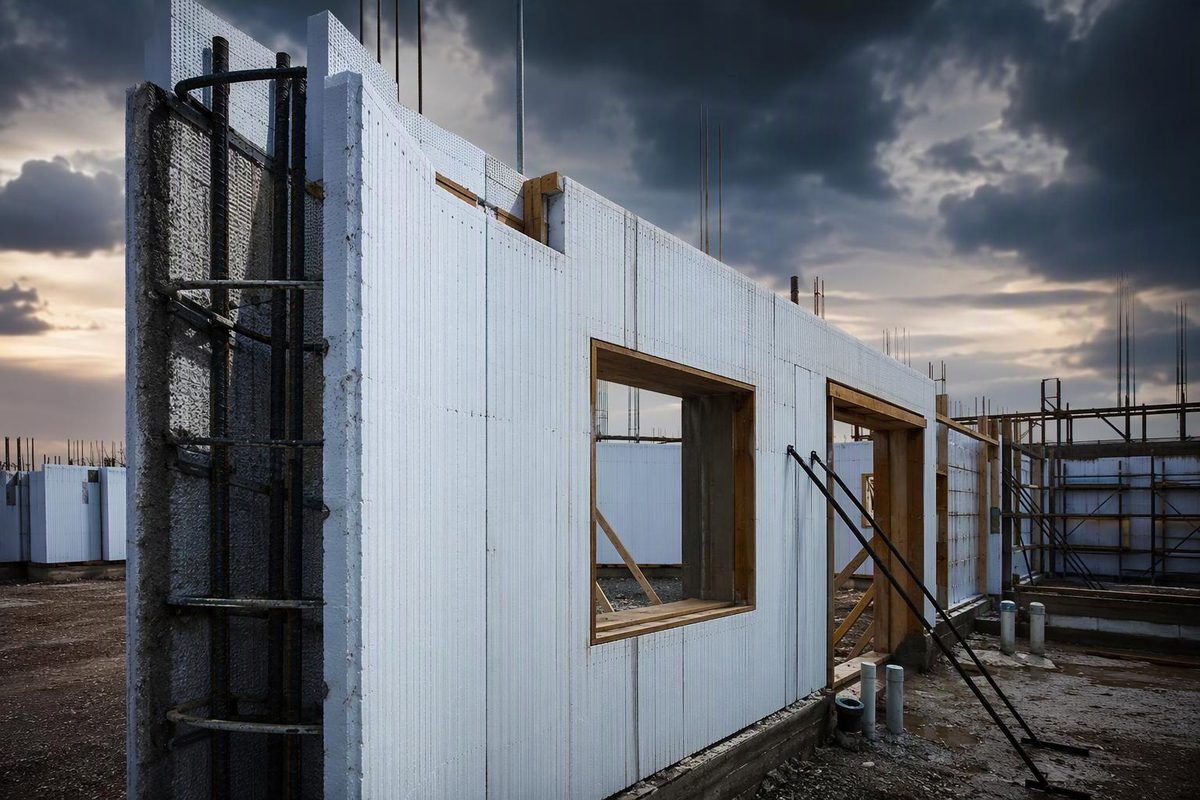
Using insulated concrete forms (ICFs) means designing a reinforced concrete wall, not simply substituting foam blocks for wood framing. The forms establish the wall geometry, hold reinforcing steel and wet concrete, remain as insulation, and usually provide strips for attaching finishes.
A typical flat-wall ICF has two expanded-polystyrene (EPS) faces connected by plastic ties. Concrete fills the continuous cavity between them. Waffle, screen-grid and post-and-beam systems produce different concrete geometries, so products are not interchangeable without revisiting the structural design. ACI identifies flat-wall ICFs as the most common type and notes that each proprietary system has specific characteristics and limitations (ACI PRC-560-22).
Select the system before completing the drawings
Obtain the current installation manual and evaluation report for the selected product, then coordinate:
- concrete-core and overall wall thicknesses;
- form height, length and cutting module;
- reinforcing supports and clear space within the core;
- fastening-strip location and tested capacity;
- corner, taper-top and brick-ledge units;
- rough-opening bucks and sill depth;
- floor, roof and stair connections;
- service penetrations and embedded plates;
- compatible water-control, air-barrier and finish systems.
The drawings must distinguish concrete-core thickness from total form thickness. For example, Nudura’s 4-, 6-, 8-, 10- and 12-inch concrete cores produce forms 9¼, 11¼, 13¼, 15¼ and 17¼ inches wide before finishes. Its fastening strips are spaced 8 inches on center and recessed ⅝ inch behind the foam face (ICC-ES ESR-2092). These dimensions are product-specific, but they show why “8-inch ICF” is an ambiguous note.
The engineer should design the concrete and reinforcement for applicable gravity, wind, seismic and soil loads. The IRC contains prescriptive provisions for flat-wall ICF construction within stated limits; construction outside those limits requires another recognized design route or engineering. Confirm that the product report addresses the adopted code edition and intended use.
Treat the core as reinforced concrete: bars require the specified size, spacing, lap, development, cover and position. Congested lintels, narrow piers and intersecting walls also need enough clear space for concrete to flow around the steel. ACI advises considering form geometry and reinforcement placement when proportioning the mix for flow and consolidation.
Coordinate everything that must cross the core
Changes after the pour can require cutting concrete. Before stacking begins, prepare a coordinated penetration and embed plan showing:
- sleeves for plumbing, electrical, communications and ventilation work;
- beam pockets and bearing elevations;
- ledger bolts, anchor bolts, straps and hold-downs;
- mounting plates for canopies, rails and heavy equipment;
- roof-to-wall and floor-to-wall connections;
- openings and their additional reinforcement.
Cast-in anchors transfer load to concrete; foam does not. Finish fasteners must engage the molded webs or another designed substrate. Fox Blocks states that its EPS has no fastener holding capacity, while its plastic webs do (Fox Blocks technical FAQ). Use capacities for the selected form, fastener and load rather than treating the strips as ordinary studs.
Window and door bucks restrain fresh concrete and may later receive the unit or its anchors. Draw the buck material, attachment, rough-opening allowance and reinforcement—not just an opening rectangle. The sill also needs a drainage path. A typical drained-opening sequence uses a sloped sill, pan or formable flashing connected to the wall’s water-control layer, followed by jamb and head flashing. PNNL’s generic drained-window detail illustrates that relationship and places the interior perimeter air seal after the window is set and shimmed; adapt the sequence to the ICF, cladding and window manufacturers’ instructions (PNNL window-detail guidance).
Stack, reinforce and brace as one operation
A level footing or slab simplifies every course above it. Lay out both wall faces, corners, openings and dowels before setting forms. Complete each course around the perimeter, stagger vertical joints, and place horizontal reinforcement as stacking proceeds. Install vertical bars, bucks, sleeves and embeds in the sequence required by the selected system.
Bracing is both an alignment system and temporary works. It must keep the forms straight and plumb under fresh-concrete pressure, support safe access, and permit adjustment during and immediately after placement. Brace corners, wall runs and openings according to the manufacturer’s instructions. Do not copy spacing from another brand: form height, tie geometry and allowable placement pressure vary.
Before ordering concrete, establish a hold point to verify:
- wall location, height, line, level and plumb;
- reinforcement, laps, lintels and dowels;
- opening dimensions and cross-bracing;
- sleeves, embeds, ledgers and anchors;
- cut forms, joints and locally weak areas;
- bracing, access and pump position;
- approved mix, delivery sequence and consolidation equipment.
A current manufacturer guide specification likewise calls for coordinated shop drawings of walls, openings, penetrations and structural embeds, followed by documented pre- and post-pour checks (Nudura ICF guide specification).
Control concrete placement
Concrete strength comes from the structural documents; workability must also suit the cavity, reinforcement and pumping method. Do not address poor flow by casually adding water on site. Confirm aggregate size, slump, admixtures and placement rate with the engineer, concrete producer and ICF supplier.
Place concrete in controlled horizontal lifts and make repeated passes around the structure. Alternate placement on opposite sides of bucks so fresh-concrete pressure does not displace them. Consolidate below sills and around lintels, pockets and dense reinforcement without damaging the forms or over-vibrating.
Exact limits are system-specific. BuildBlock’s 2026 pocket guide, for example, calls for a steady flow in 4-foot lifts and says a typical 8- to 10-foot wall can be filled in two or three passes, followed by final alignment before the concrete sets (BuildBlock installation guide). These figures are not universal specifications; the selected manufacturer’s instructions should govern the placement plan.
Assign people to the hose, consolidation, wall observation and alignment. Keep repair materials ready, but inspect first: unsupported cuts, damaged foam, excessive placement pressure and over-consolidation can contribute to blowouts.
Complete the enclosure
ICF insulation is continuous across most of the wall, reducing framing-related thermal bridges. Concrete adds thermal mass, which delays heat flow, but mass is not a substitute for the product’s tested R-value. Building America cites comparative testing in which the studied ICF houses had a 9% better whole-wall R-value and were 10% more airtight than otherwise identical stick-framed houses; those study results are not performance guarantees for every ICF building (PNNL ICF guide). Seal seams and transitions as required by the selected system.
Do not assume the exposed foam face alone completes water control. Above grade, use the flashing, drainage-plane and cladding details required for the evaluated assembly. Where an adhered membrane is specified, verify its adhesion and chemical compatibility with the EPS and adjacent sealants. Below grade, specify compatible dampproofing or waterproofing and drainage for the site conditions. The cited ICC-ES report requires compatible below-grade materials and prohibits backfilling until the supporting floor system is installed unless the wall was designed to stand free.
Cover interior foam with the approved thermal barrier—commonly gypsum board—using the evaluated fastening schedule. Size exterior fasteners for the cladding gravity and wind loads using the product report. For brick veneer, coordinate the support, cavity, flashing, weeps and ties as a complete brick-veneer assembly, rather than relying on a molded ledge alone.
The pour makes incomplete coordination permanent. Resolve the core and reinforcement, openings and connections, placement procedure, and continuity of the water, air, thermal and fire-control layers before concrete arrives.