
Sonotube Concrete Forms: Choose the Tube, Then Detail the Pier
Choose Sonotube concrete forms by height, finish and placement method. Calculate concrete volume and coordinate footing, reinforcement and anchor details.
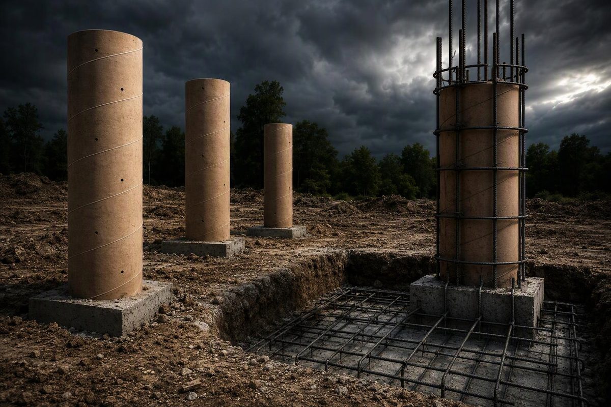
Sonotube concrete forms are single-use fiber tubes that hold fresh concrete in a round shape while it sets. The tube forms the surface; it does not establish the load capacity of the finished pier or column. Diameter, footing area, reinforcement and connections still need a design. Sonoco’s technical guidance distinguishes the form from the structural support and identifies loads, soil characteristics and local codes as design considerations.
Sonotube is a brand, not a specification for every cardboard concrete-forming tube. Even within the brand, below-grade Builder’s Tube forms and commercial column forms have different height, consolidation and stripping instructions.
Choose the product by exposure, height and finish
Three product distinctions change the work:
| Product | Intended role | Important coordination point |
|---|---|---|
| Builder’s Tube | Primarily below-grade round supports | Manufacturer permits placement up to 3 feet above grade; support is required when projection exceeds 2 feet |
| Commercial | Demanding column-forming applications | Rated for full liquid-head pressure up to 20 feet; still needs positioning and bracing |
| Finish Free | Columns where the exposed surface matters | Interior coating eliminates the tube’s spiral seam and vertical markings; protect that coating during handling and placement |
These distinctions come from Sonoco’s Builder’s Tube, Commercial and Finish Free product information. A long retail tube is not automatically suitable for a freestanding column of the same height.
“Full liquid head” describes the pressure fresh concrete exerts against the form before setting, not the finished column’s capacity. For exposed architectural concrete, specify the required surface rather than simply calling for “Sonotube.” A coated form addresses seam markings, but handling and concrete placement remain part of achieving the finish.
Separate pier diameter from footing size
A foundation section should show three separate dimensions:
- Pier diameter: the round concrete shaft formed by the tube.
- Footing dimensions: the bearing base, which may be wider than the shaft.
- Founding depth: the elevation at which the footing bears on suitable soil, with the required frost protection.
Do not choose a tube merely because a post base fits on top. That checks one connection detail, not soil bearing, uplift or lateral resistance.
For U.S. residential decks within its scope, the American Wood Council’s DCA 6 guide, based on the 2015 IRC, relates footing size to framing spans and stated load and soil assumptions. It also calls for field verification of bearing conditions and confirmation of frost depth with the local authority. Its tables are not a universal foundation design or a substitute for the locally adopted code. See the guide’s footing requirements and limitations.
Coordinate the tube-to-footing junction explicitly: base width and thickness, shaft position, reinforcement continuity and whether the concrete is placed together or across a specified construction joint. The same distinction between bearing area and member size applies when detailing a concrete foundation for a wall.
Calculate concrete from the inside diameter
Tube sizes can be nominal. Sonoco’s Builder’s Tube instructions say to measure when diameter is critical. Use the measured inside diameter, not the outside diameter, for concrete quantities and clearance checks.
For a cylindrical shaft:
Volume in cubic feet = π × (D ÷ 24)² × H
Here, D is inside diameter in inches and H is concrete height in feet. Divide cubic feet by 27 for cubic yards.
| Assumed inside diameter | Concrete per foot of height | Concrete for a 4-foot shaft |
|---|---|---|
| 8 inches | 0.349 ft³ | 1.396 ft³ |
| 10 inches | 0.545 ft³ | 2.182 ft³ |
| 12 inches | 0.785 ft³ | 3.142 ft³ |
| 16 inches | 1.396 ft³ | 5.585 ft³ |
These are calculated cylinder volumes, excluding enlarged footings and waste. For bagged concrete, divide the total volume by the selected mix’s stated yield per bag and round up. A 16-inch shaft takes about 78% more concrete than a 12-inch shaft of equal height: volume changes with diameter squared.
Coordinate setup and concrete placement
Before pouring, check centerlines, top elevations, roundness and plumb. Secure the base and brace the tube for the selected product and placement conditions. Support and secure the reinforcement at its specified cover; coordinate cage size and anchor embedment before ordering the tube. See rebar cage clearances and constraints.
Keep stored forms dry and supported. Sonoco rates Commercial forms for up to 72 hours of moisture exposure, but its field-use brochure specifically excludes standing water. Rain resistance is not permission to install a tube in a flooded excavation.
Consolidation instructions are product-specific. Sonoco’s Builder’s Tube instructions prohibit mechanical vibration. Its Commercial brochure requires vibration during placement. The Finish Free instructions call for an internal vibrating needle kept clear of the coating and prohibit vibration from outside. These field-use brochures are dated 2016; confirm the instructions supplied for the actual form and coordinate the placement method with the concrete specification.
Plan stripping and curing separately
Builder’s Tube is designed to remain in place, rather than produce a stripped architectural surface. The Commercial and Finish Free brochures recommend stripping after the concrete has set, typically 24–48 hours after placement for easier removal. Finish Free instructions also say not to leave the form on the column for more than five days. These are form-removal recommendations—not permission to load the column. Follow the project specification and required concrete strength for subsequent work.
Continue the specified curing after stripping, including moisture and temperature protection on newly exposed surfaces. The National Ready Mixed Concrete Association’s curing guidance explains that cold conditions slow strength gain and can delay form removal and subsequent construction.