
When Synthetic Fiber Can Replace Slab Reinforcement
Learn when macro-synthetic fiber can replace distributed slab steel, which bars must stay, and how to compare project quotes per square foot.
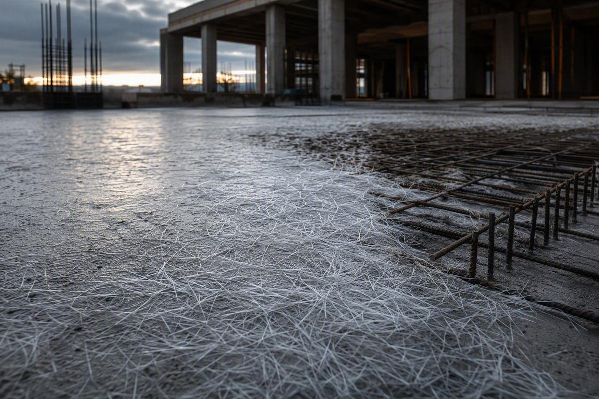
Yes—but only when the specified steel serves as distributed secondary reinforcement and an engineered macro-synthetic fiber system delivers the required post-crack performance. Synthetic fiber is not a one-for-one substitute for rebar carrying primary flexure, continuity, anchorage, thrust, joint transfer, or concentrated forces. Removing any specified steel requires project-specific calculations and written approval from the engineer of record.
Select the slab conditions, then enter comparable contractor quotes to screen the reinforcement choice and calculate installed cost per square foot.
This screening tool separates distributed crack-control reinforcement from steel in a structural load path. It does not replace the engineer of record’s calculations or approval.
The reinforcement function and proposed system have not yet been established.
Written project-specific approval is required before any reinforcement is removed.
| Condition | Fiber-Alone Screening | Likely Direction | Steel That Commonly Remains |
|---|---|---|---|
| Secondary crack-control steel; macrofiber performance verified | Candidate | Engineered macro-synthetic replacement may be evaluated | Any separately detailed local reinforcement |
| Primary flexural or continuity reinforcement | Not a generic substitution | Retain rebar or provide a separately engineered alternative | Load-path reinforcement |
| Dowels, tie bars, hairpins, thrust, anchorage, or connections | No | Hybrid system or retained conventional reinforcement | All steel required for the defined force transfer |
| Forklifts, trucks, racks, or machinery | Full design required | Macrofiber or hybrid only after load, support, edge, and joint analysis | Local steel at concentrated or vulnerable locations as designed |
| Low-dose monofilament microfiber only | Usually no | Use for plastic-shrinkage control, not presumed hardened-concrete equivalence | Specified rebar or welded-wire reinforcement |
Source basis: ACI 544.4 design topics and the ASTM C1116/C1609 roles summarized in the article. Cost results use only figures entered by the reader; no market prices or structural equivalence are assumed.
The phrase “slab on grade” describes how the concrete is supported, not why steel appears on the drawings. The first task is to identify the reinforcement’s function. Shrinkage-and-temperature reinforcement distributes cracking and limits crack widths. Primary flexural reinforcement resists calculated tension from bending. Bars may also anchor structural elements, transfer thrust, tie joints, or strengthen concentrated-load locations.
Industry guidance recognizes macrofibers as an option where conventional steel serves as secondary reinforcement, while distinguishing that use from primary reinforcement in a defined load path (Fiber Reinforced Concrete Association). A hybrid design is often the practical answer: macro-synthetic fibers reinforce the general floor area while bars, dowels, tie bars, hairpins, and local reinforcement remain at critical details.
Microfibers Do Not Perform the Same Job as Macrofibers
Synthetic fibers differ in dimensions, geometry, material, bond, dosage, and tested behavior. Industry guidance divides them by equivalent diameter:
- Microfibers: less than 0.3 mm
- Macrofibers: at least 0.3 mm
Low-dose monofilament micro-synthetic fibers are used primarily to reduce plastic-shrinkage cracking while concrete is young. They can interrupt small cracks before the concrete develops its hardened properties, but that does not make them equivalent to reinforcing bars or welded-wire reinforcement acting after cracking.
Fibrillated microfibers are a limited exception. Some have historically replaced the lightest welded-wire reinforcement used only for temperature-and-shrinkage control in selected slabs on ground. That is a product- and application-specific use. It does not support replacing bars responsible for primary flexure, anchorage, continuity, or concentrated forces.
Structural macro-synthetic fibers are the relevant class when the design requires residual capacity after the concrete matrix cracks. Fibers distributed through the mixture bridge cracks that intersect them and contribute post-crack residual flexural performance.
Rebar works differently. It is sized, spaced, oriented, positioned at a selected depth, and developed through a defined force path. Macrofiber performance must therefore be evaluated through testing of the proposed fiber-reinforced concrete system, not by converting fiber weight directly into steel weight.
Manufacturer guidance likewise separates microfibers used primarily for plastic-shrinkage control from macrofibers intended to provide residual post-crack performance. It also states that slab dosage depends on loading, thickness, and concrete grade (Sika). A familiar dosage or the term “fiber mesh” is not an engineering basis for deleting steel.
A complete proposal identifies the manufacturer, exact product, constituent material, geometry, dimensions, bond characteristics, dosage, mixing requirements, and product-specific residual-flexural results.
Replacement Depends on What the Steel Does
Distributed Crack-Control Steel May Be Replaceable
When bars or welded-wire reinforcement serve only shrinkage-and-temperature crack control, engineered macro-synthetic replacement may be considered. The proposed product and dosage must provide the residual performance required by the slab design.
A light bar size or wide spacing does not prove that the steel is secondary. Structural notes, slab schedules, details, calculations, and design criteria must establish its purpose. Apparently light reinforcement may connect to another force-resisting detail.
Steel in a Defined Load Path Usually Stays
A generic fiber substitution is inadequate when reinforcement carries primary flexure, continuity forces, anchorage, thrust, joint transfer, or concentrated loads. Common locations requiring retained steel or a separately designed system include:
- Bars developed into foundations or thickened slabs
- Hairpins connected to columns or building frames
- Reinforcement receiving wall or frame thrust
- Bars around pits, trenches, sumps, and major openings
- Reinforcement at columns, rack posts, and machinery supports
- Edge and corner reinforcement
- Dowels and tie bars at joints
- Bars connecting the slab to structural elements
Distributed fibers may complement these details. They do not automatically replace them.
Ground Support Does Not Eliminate Structural Demands
In many ground-supported slabs, thickness and subgrade support carry the principal loads while distributed reinforcement controls crack width. That arrangement can make macrofiber replacement plausible, but the calculation still must consider slab thickness, concrete properties, support stiffness, panel dimensions, load position, edges, joints, and expected cracking.
Forklifts and trucks do not create an automatic answer for or against fiber. The design needs wheel loads and spacing, contact area, travel paths, impact assumptions where relevant, joint condition, edge loading, slab properties, and subgrade support. Rack posts, equipment legs, columns, and building-frame forces must be evaluated separately from general floor traffic.
Hybrid Reinforcement Often Matches the Actual Risk
A hybrid floor can use macro-synthetic fibers as distributed reinforcement in ordinary panels while retaining steel where forces are directional or concentrated. Typical retained elements include dowels at construction joints, tie bars, reinforcement around columns and rack-post foundations, edge bars, hairpins, thrust reinforcement, and bars at pits or openings.
This is not a failed substitution. It separates broad crack-control needs from details that require deliberately positioned and developed steel. ACI’s fiber-reinforced-concrete design guide covers slabs on ground, hybrid reinforcement, flexural design, crack-width control, joints, and reinforcement-replacement analysis (American Concrete Institute).
ASTM And ACI References Answer Different Questions
Listing ASTM C1116, ASTM C1609, and ACI 544.4 on a submittal does not by itself approve a substitution.
| Reference | Principal Role | What It Does Not Establish by Itself |
|---|---|---|
| ASTM C1116/C1116M | Classification and supply of uniformly mixed fiber-reinforced concrete | Structural equivalence to a bar grid |
| ASTM C1609/C1609M | Testing of post-crack flexural behavior | The project’s required performance or approval |
| ACI 544.4 | Design guidance using characterized fiber-reinforced-concrete performance | Universal permission or a fixed fiber-for-steel conversion |
ASTM C1116/C1116M classifies synthetic fiber-reinforced concrete as Type III and addresses batching or continuous mixing, tolerances, workability, air content, acceptance, and fiber balls. It does not cover field placement, consolidation, curing, or protection. Nor does it establish that a mixture is structurally equivalent to specified structural rebar. The ASTM page cited here identifies a historical edition and points to a newer active version, so the contract edition must be confirmed (ASTM International).
ASTM C1609/C1609M beam testing characterizes flexural behavior after cracking. The useful evidence is the measured result for the proposed product, dosage, and concrete system. A report for one fiber or dosage does not establish the performance of another. Saying a product “meets ASTM C1609” identifies a test method, not the residual strength required by the project.
ACI 544.4 provides the design pathway connecting characterized fiber performance to slab requirements. It does not create a universal conversion between pounds of fiber and an area or weight of steel. Final design must use the applicable standards, adopted code provisions, contract documents, and any stricter owner or authority requirements.
The Design Requires Slab, Load, Support, And Joint Data
A credible macrofiber design starts with required performance rather than a standard sales-sheet dosage. Its loading inputs may include wheel loads, wheel spacing, contact areas, travel paths, rack-post loads, equipment legs, line loads, impact effects, edge and corner positions, structural connections, and construction-stage loading.
The slab information should include nominal and permitted minimum thickness, concrete compressive and flexural properties, panel dimensions, reinforcement being replaced, openings, pits, embedded items, transitions, edge conditions, continuity assumptions, crack-control criteria, and tolerances that could reduce effective thickness.
Support assumptions also matter. The calculation should identify the subgrade or base stiffness, compaction requirements, base material and thickness, drainage, moisture sensitivity, settlement risk, utility trenches, disturbed soil, and possible loss of support. Fiber cannot compensate indiscriminately for disappearing or poorly characterized support.
The joint plan must define layout and spacing, saw-cut timing and depth, construction and isolation joints, dowels or plates, tie bars, edge protection, and load-transfer assumptions. Fiber should not be assumed to repair an inadequate joint system or justify wider spacing unless that change is separately designed and approved.
The fiber-system portion must name the product, manufacturer, material, length, equivalent diameter, geometry, bond characteristics, dosage, associated concrete mixture, and product-specific ASTM C1609 results. Supplier software can assist a qualified designer, but unexplained output does not replace transparent assumptions and independent review.
Application Type Changes the Level of Scrutiny
| Application | Screening Verdict | Conditions |
|---|---|---|
| Light residential flatwork | Possibly suitable | Existing steel must serve only crack control; verify support, joints, product, dosage, specifications, and approval |
| Commercial floors | Often worth evaluating | Requires residual-performance data, loads, joint design, support assumptions, and local detailing |
| Industrial or heavy-traffic slabs | Possible as an engineered design | Calculate wheels, racks, equipment, edges, joints, impact, thickness, support, and concentrated forces |
| Slabs tied into structural systems | Distributed replacement may be limited | Retain or redesign anchorage, thrust, continuity, hairpins, and structural connections |
A residential slab can be a candidate when its steel serves only temperature-and-shrinkage control. Monofilament microfiber may still be useful for early plastic-shrinkage control, but it should not be represented as a structural macrofiber system.
Commercial floors require attention to partitions, shelving, equipment, entrances, penetrations, columns, and construction joints. The label “commercial slab” is not a design criterion.
Warehouse, distribution, manufacturing, forklift, truck, and rack-supported floors require full calculations. A macrofiber system may reinforce the general floor while conventional steel remains around rack posts, columns, machinery bases, pits, dock details, or vulnerable edges.
The strongest warning applies where the slab participates in a building load path. Hairpins, anchor forces, structural continuity, tied foundations, and thrust reinforcement require a defined means of transferring force. None of these slab-on-grade conclusions should be extended automatically to suspended slabs, beams, columns, decks, balconies, or cantilevers.
Published Cost Data Does Not Support a Universal 2026 Rate
No verified material-and-labor figures in the available sources support a defensible nationwide cost per square foot for macrofiber, welded-wire reinforcement, rebar, or a hybrid system. The supplied Chicago Construction News page concerning tariff and labor comparisons is currently unavailable, so it cannot substantiate a project cost conclusion (Chicago Construction News).
The calculator above therefore uses contractor or supplier quotes entered by the reader rather than fabricated market rates. Each quote should cover the same slab area and clearly separate material and labor. A valid comparison also includes mixture adjustments, batching controls, pumping and finishing effects, retained local steel, testing, submittal preparation, and engineering review.
Lower steel-placement labor does not prove structural equivalence. Synthetic fibers do not rust, and removing a distributed grid may reduce handling and support work, but corrosion resistance and schedule savings do not establish residual capacity, crack-width control, anchorage, or continuity.
Construction Controls Remain Part of the Design
Macrofibers can alter workability and how concrete moves through pumps, chutes, and placement equipment. The effect depends on the exact product, dosage, mixture, equipment, and crew. Adding unapproved water to recover workability is not an acceptable default response. The producer, supplier, contractor, and design team must resolve placement through approved mixture proportioning and suitable admixtures.
A trial placement may be appropriate where dosage, pumping, appearance, specialized finishing, or tight tolerances create execution risk. Quality control should verify the product and dosage, addition sequence, mixing time, dispersion, absence of fiber balls, batch records, delivery workability, air content where specified, temperature limits, sampling, and treatment of nonconforming loads.
ASTM C1116 addresses supplied-material controls, but its scope ends before placement, consolidation, curing, and protection. Project specifications must cover those operations. Fibers may reduce certain cracks, control crack width, or provide residual behavior; they do not guarantee a crack-free floor.
Written Approval Must Identify What Leaves And What Stays
A complete substitution package should establish the original reinforcement’s purpose and provide drawings, slab schedules, load criteria, bar or wire size and spacing, crack-control requirements, and applicable code provisions. Calculations should show loads, slab properties, panel dimensions, discontinuities, support assumptions, joint behavior, design method, required post-crack performance, and comparison with the reinforcement proposed for removal.
Revised drawings should identify every retained dowel, tie bar, hairpin, edge bar, thrust bar, connection, opening detail, equipment detail, and concentrated-load strengthening element. “Local reinforcement to remain” is not a substitute for coordinated plans and details.
Final authorization should name the approved fiber product and dosage, slab areas covered, steel permitted to be removed, steel required to remain, revised details, quality-control requirements, and limitations. Manufacturer calculations can support the package, but the engineer of record must approve the project-specific change in writing.
The decision rule is direct: no identified reinforcement function, no verified residual performance, or no written engineering approval means no substitution.