
When Fiberglass Reinforcement Makes Sense—and What Changes When You Use It
Cured GFRP bars generally should not be bent on site. Required hooks, stirrups, ties and other shapes should be factory-fabricated from an approved schedule.
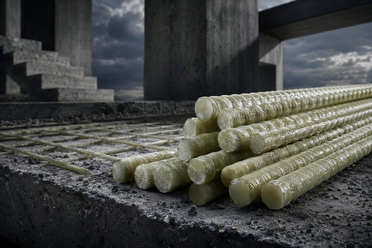
When fiberglass reinforcement makes sense—and what changes when you use it
Glass fiber reinforced polymer rebar can address problems that conventional carbon-steel reinforcement cannot solve as cleanly. It does not participate in the chloride-driven electrochemical corrosion mechanism that attacks carbon steel. It is also lightweight, electrically nonconductive, and nonmagnetic. Those qualities can be valuable in selected coastal structures, bridge elements, wastewater facilities, electrical installations, and magnetically sensitive rooms.
But GFRP rebar is not steel rebar made from a different material. Its lower stiffness, linear-elastic rupture behavior, product-specific bond, factory-fabrication requirements, and temperature-sensitive polymer matrix change how a concrete member is designed, detailed, approved, purchased, and built.
The useful question is therefore not simply, “Is GFRP stronger than steel?” It is: Does a qualified GFRP system solve a defined project problem, within the governing code scope, while meeting strength, serviceability, durability, fire, seismic, fabrication, and construction requirements?
This article is an evidence-limited overview, not a substitute for the current primary standards, locally adopted code, product evaluation report, project specifications, or structural engineering. Detailed code statements below are identified as provisions reported by the available secondary sources; editions, amendments, and legal applicability must be verified directly before design or procurement.
What GFRP rebar is—and what it is not
Glass fiber reinforced polymer, or GFRP, rebar is a composite reinforcing bar made from continuous glass fibers embedded in a cured polymer-resin matrix. Its constituents perform different functions:
- Glass fibers primarily carry tensile load.
- Resin binds and protects the fibers, transfers stress among them, and gives the bar its consolidated form.
- The surface configuration develops interaction with the surrounding concrete.
GFRP is one branch of the broader fiber-reinforced polymer, or FRP, category. FRP reinforcement may instead use carbon, basalt, or aramid fibers. Those materials are not interchangeable.
The same warning applies within the GFRP category. A property published for one product cannot automatically be assigned to another. Reported fiber and resin proportions also differ among sources and products, so a universal composition ratio is not useful for specification. The selected bar’s qualified, product-specific properties matter more than a generic range.
How a GFRP bar is made
Pultrusion is a commonly described manufacturing process for GFRP reinforcement. At a high level:
- Continuous glass fibers are fed from reels.
- The fibers are impregnated with polymer resin.
- The wet bundle is shaped and consolidated.
- It passes through a heated die, where the resin cures.
- The cured profile is pulled continuously through the production line.
- The bar is cut to length.
- A bond-producing surface is formed or applied.
Manufacturers may use sand coating, helical wrapping, molded deformation, or another surface configuration to engage the concrete. These surfaces serve a purpose comparable to steel-bar deformations, but they do not necessarily produce the same behavior. These constituent roles and manufacturing steps are summarized in manufacturer technical material, which should be treated as background rather than project qualification evidence (GFRP definition and manufacturing overview).
This composite construction is also why “fiberglass rebar” is not merely a glass rod. Resin chemistry, cure, fiber alignment, surface construction, and manufacturing quality are integral to the finished bar.
GFRP versus steel: compare behavior, not headline strength
Single-number comparisons hide the differences that matter most. A useful evaluation compares complete reinforcement systems.
| Issue | GFRP rebar | Carbon-steel rebar | Project implication |
|---|---|---|---|
| Corrosion mechanism | Nonmetallic; not susceptible to chloride-driven electrochemical corrosion | Can corrode when protective conditions are lost and moisture, oxygen, and chlorides reach the steel | GFRP can be attractive where corrosion drives maintenance or service-life concerns |
| Handling weight | Substantially lighter | Heavier | Freight, lifting, and manual handling may favor GFRP, but installed quantities can differ |
| Tensile behavior | Can have high tensile strength; properties vary by product and bar size | Familiar grades and established design properties | Tensile strength alone cannot determine substitution |
| Elastic modulus | Generally well below steel | Much higher stiffness | GFRP members may require more reinforcement or different geometry for crack and deflection control |
| Ductility | Generally linear elastic until rupture, without a yield plateau | Yields and can develop substantial post-yield deformation | Failure-mode selection, analysis, and resistance factors differ |
| Electrical behavior | Low conductivity | Conductive | GFRP can support electrical-isolation objectives |
| Magnetic behavior | Nonmagnetic | Magnetic | GFRP may be useful around MRI equipment and other sensitive installations |
| Thermal response | Polymer matrix is temperature-sensitive | Established design framework, although steel also loses strength when heated | Ambient bar strength does not establish fire resistance |
| Bond | Depends on surface, diameter, cover, confinement, casting position, and anchorage | Rib geometry and design rules are highly standardized | Steel development and splice practices cannot simply be copied |
| Fabrication | Cured bars generally cannot be bent or welded in the field | Commonly field-cut and, where permitted, field-fabricated | GFRP bend schedules require earlier coordination |
| Availability | Product, size, shape, and lead time vary by supplier | Broadly available through established supply chains | Procurement risk requires early confirmation |
| Cost | Material and installed costs are project-specific | Familiar pricing and labor assumptions | Initial and lifecycle costs must be compared transparently |
Corrosion resistance is a mechanism-specific advantage
Because GFRP is nonmetallic, it does not undergo that same chloride-driven mechanism. This is its clearest distinction in marine, coastal, deicing-salt, wastewater, and certain chemical exposures.
That does not mean every GFRP product is immune to every form of degradation. “Does not rust like steel” is supportable; “universally corrosion-proof” is not.
Low weight helps construction, but ratios can mislead
GFRP bars are substantially lighter than steel bars of a similar nominal size. That can reduce handling effort and alter shipping, crane, and staging requirements.
A universal project-level weight ratio is nevertheless misleading. Product densities vary, and an equivalent design may require a different number, size, spacing, or arrangement of bars. Weight should be compared twice: first per unit length of the selected products, then for the complete engineered reinforcement package.
Tensile strength and stiffness are different questions
A bar can have high tensile strength while stretching much more than steel under a comparable stress. Published product-oriented data consistently describe GFRP’s elastic modulus as substantially lower than steel’s, but the exact design value must come from the selected product’s qualified documentation.
That distinction drives member behavior. Lower stiffness can increase curvature, deflection, and crack width. The required reinforcement may therefore be governed by serviceability rather than nominal tensile capacity.
A claim that GFRP is “stronger than steel” is incomplete unless it identifies:
- the steel and GFRP products being compared;
- whether strength means mean, nominal, guaranteed, or design tensile strength;
- the bar size and test method;
- applicable environmental and time-dependent reductions;
- and whether member capacity, deflection, cracking, bond, shear, or fire governs.
High tensile strength does not automatically permit fewer bars. Crack control, deflection, development, shear behavior, sustained-load limits, fire requirements, and governing design provisions may control first.
GFRP does not yield like steel
Conventional reinforcing steel has a yield region that permits substantial post-yield deformation. GFRP generally remains linear elastic until rupture and does not provide the same yield plateau.
That difference affects desired failure mode, resistance factors, redundancy, analysis methods, and detailing. It also means a GFRP design cannot be established by replacing the steel area in an existing schedule with the same area of fiberglass reinforcement.
Designers should not assume that a GFRP member will reproduce steel-reinforced behavior such as yielding, plastic rotation, or inelastic redistribution. Those behaviors must be addressed through the applicable GFRP design method and the overall structural system.
Cost must be assembled, not assumed
Quoted bar prices do not represent installed system cost. A useful estimate separates:
- bar material;
- freight and available shipping lengths;
- unloading and handling;
- factory bends and special shapes;
- chairs, spacers, and ties;
- engineering and submittal effort;
- installation labor;
- inspection and quality documentation;
- expected repair and maintenance costs;
- service-life assumptions;
- and uncertainty.
GFRP may create lifecycle value when it avoids a credible corrosion problem. It may not create the same value in a dry interior element where carbon steel is inexpensive, familiar, available, and adequately durable. The result depends on project conditions rather than a fixed material premium or an unverified service-life promise.
GFRP and steel are different reinforcement systems, not interchangeable commodities.
Why serviceability, bond, and failure mode can control the design
Concrete reinforcement does more than resist ultimate tensile force. It affects how a member cracks, deforms, anchors forces, redistributes load, and approaches failure.
Lower modulus changes cracking and deflection
Because GFRP is less stiff than steel, a GFRP-reinforced member can develop greater reinforcement strain at a comparable stress. Wider cracks and greater deflection may result unless reinforcement area, spacing, member depth, loading, and other design variables are adjusted.
A 2023 professional summary of ACI CODE 440.11-22 reports that deflection must be calculated for GFRP flexural members and that additional reinforcement may be needed to limit crack widths. It also describes GFRP-specific resistance factors and detailing requirements (professional summary of GFRP code provisions).
Early member sizing should therefore consider:
- immediate deflection;
- applicable long-term deformation;
- crack-width criteria;
- reinforcement spacing;
- member depth;
- bar stress under service loads;
- and the effect of cracking on effective stiffness.
A member that passes a nominal ultimate-strength check may still fail the project’s serviceability requirements.
Failure mode must be deliberately selected
Material-specific resistance factors and restrictions on analysis that depends on inelastic redistribution may also apply.
This affects reinforcement quantity, neutral-axis behavior, member proportions, continuity assumptions, and system redundancy. The issue is not merely whether a bar can carry a calculated tensile force. It is how the member behaves as it approaches its limit state and what deformation capacity exists before rupture.
Bond is not imported from a steel schedule
Bond transfers force between reinforcement and concrete. Relevant GFRP variables include:
- concrete compressive strength;
- embedment and development length;
- clear cover;
- bar diameter;
- surface configuration;
- casting position and depth;
- transverse confinement;
- bend radius;
- and tail length for hooked bars.
A peer-reviewed 1996 program tested 102 specimens under monotonic static loading: 48 beam specimens, 18 pull-out specimens, and 36 hooked-bar specimens. Reported endpoints included concrete splitting, bar pull-out, and bar fracture. Variables included concrete strength, embedment, cover, diameter, casting depth, bend radius, and tail length (University of Arizona record of the bond study).
That work helps explain why bond must be treated as a design problem. It does not provide universal values for present-day projects. The available abstract does not contain the material details, equations, or numerical results needed for design, and the research predates current products and codes.
A 1995 research program likewise compared flexural behavior in GFRP- and steel-reinforced beams. The supplied abstract describes three beam series and two GFRP bar types, establishing that comparative beam behavior has a substantial research history. It does not report the results needed to infer current capacity, durability, or code compliance (abstract of the 1995 GFRP beam study).
Without the governing code equations and selected product’s qualified properties, universal lap, development, hook, or splice dimensions would be misleading. Those values belong in engineered drawings and schedules.
Where GFRP can be a credible choice—and where caution rises
GFRP is most credible where one of its distinctive properties solves a documented project problem.
Strong candidate conditions
Corrosion exposure. Candidate applications include selected bridge elements, marine and coastal structures, seawalls, wastewater facilities, tanks, culverts, foundations, and concrete exposed to aggressive chemicals. The case is strongest when carbon-steel corrosion is a credible service-life or maintenance driver.
Magnetic neutrality. MRI rooms and other magnetically sensitive spaces may benefit from nonmagnetic reinforcement. The equipment and facility teams should define exactly where ferrous material is restricted; reinforcing bars are only one part of that zone.
Electrical isolation. Substations, rail-related work, and specialized industrial facilities may benefit from low-conductivity reinforcement. Grounding, bonding, fault-current, lightning, and electromagnetic requirements still require coordinated electrical engineering. Nonconductive reinforcement does not resolve the entire electrical system.
Weight or access constraints. Lightweight bars may simplify manual movement in restricted-access sites or reduce lifting demands. That benefit should be measured against support needs, factory fabrication, shipping lengths, and the final reinforcement quantity.
Government-derived bridge guidance uses deliberately qualified language: deformed or sand-coated GFRP bars may be suitable for selected normal-weight-concrete decks, slabs, beams, girders, piles, piers, footings, and railings, while directing designers to examine the limitations of the applicable guidance (DoD-derived GFRP bridge guidance). This is a candidate list, not blanket permission.
Early decision matrix
| Project condition | What favors GFRP | What raises caution | Required early check |
|---|---|---|---|
| Chloride exposure | Avoids steel’s chloride-driven electrochemical corrosion | Other durability mechanisms still require evaluation | Exposure definition, resin system, qualified durability data |
| Chemical exposure | Nonmetallic reinforcement may avoid steel corrosion | Compatibility varies with chemical, concentration, temperature, stress, and duration | Product-specific environmental evidence |
| Magnetic neutrality | Nonmagnetic reinforcement can address equipment constraints | Ferrous chairs, ties, embeds, and adjacent systems may defeat the objective | Equipment-vendor and MEP requirements |
| Electrical isolation | Low conductivity can support isolation goals | Complete electrical safety and grounding design still governs | Electrical-engineer review |
| Serviceability sensitivity | Can work with suitable member and reinforcement design | Lower modulus can increase cracking and deflection | Full service-load analysis |
| Significant seismic demand | Use may be possible only within narrow adopted provisions | Lack of yielding creates substantial restrictions | Seismic category, structural role, and governing text |
| Required fire rating | May be possible with accepted evidence | Temperature-sensitive matrix; ambient properties are insufficient | Assembly calculation or testing and official approval |
| Elevated operating temperature | Product may work below verified limits | Margin to glass-transition temperature may govern | Product Tg and maximum credible service temperature |
| Field-bending needs | Manageable if shapes are fully coordinated | Cured bars generally should not be field-bent | Approved bend schedule before procurement |
| Uncertain approval status | An evaluated product may offer an approval path | Generic “fiberglass rebar” is insufficient | Code edition, evaluation report, and conditions of use |
Applications requiring heightened caution
The available professional summary reports absent provisions or restrictions in areas including prestressing, lightweight concrete, diaphragms, shear friction, deep beams, two-way joists, precast connections, and some seismic uses. “No provision” does not prove that every conceivable application is physically impossible. It means the cited document does not provide a routine design path, potentially creating an alternative-method, testing, or specialist-review burden.
Broad commercial claims that GFRP is suitable for nearly every conventional application are not supported by the available code-oriented evidence. High-rise frames, heavily cyclic systems, fire-critical members, field-adjusted work, and details that depend on steel yielding warrant particular scrutiny.
Hybrid use may be rational—but must be designed
A project might use GFRP in a splash zone, bridge deck, MRI enclosure, or electrically sensitive area while retaining steel elsewhere. This can concentrate the material’s advantages where they matter most.
“Hybrid” is a strategy, not a standard detail. The engineer must resolve load paths, stiffness changes, crack behavior, continuity, development, transitions, constructability, and inspection. A note saying “GFRP where exposed” is not a complete design.
Codes, standards, and the product-approval path
Code compliance is a chain. It begins with the jurisdiction and ends with an approved product used within documented conditions. A manufacturer’s statement that a bar “meets ACI” does not establish that chain.
Because the supplied evidence does not include verified current primary code texts, the following is a screening workflow—not a legal determination or complete compliance procedure.
A practical compliance workflow
-
Identify the authority having jurisdiction. Determine which state, city, county, federal agency, transportation authority, or owner controls the work.
-
Confirm the legally adopted code edition and amendments. Do not assume the newest model code is effective. Check local amendments, administrative provisions, and referenced-standard editions.
-
Classify the project and structural role. Buildings, bridges, marine facilities, and federal projects may follow different documents. Distinguish primary structural reinforcement from shrinkage-and-temperature reinforcement.
-
Determine the applicable design document. Confirm whether the project relies on ACI CODE 440.11, an AASHTO guide specification, agency criteria, a product evaluation report, or an approved alternative-material procedure.
-
Verify the material specification. The available professional summary describes ACI CODE 440.11-22 as establishing minimum strength, stability, serviceability, durability, and integrity requirements for certain cast-in-place concrete reinforced with GFRP bars meeting ASTM D7957. ASTM D7957 is a material-specification framework; naming it does not prove that an unspecified bar complies.
-
Review product documentation. Match the manufacturer, product line, production location, bar sizes, surface types, shapes, and properties to certificates and reports.
-
Read every condition of use. Check concrete type, member type, exposure, seismic category, fire conditions, temperature, design procedure, and installation limitations.
-
Submit to the authority having jurisdiction. Resolve approval questions before procurement, particularly where acceptance depends on an evaluation report or alternative-method finding.
The 2023 professional article discussed references expected in the 2024 model codes. That forecast is not proof that a particular jurisdiction adopted those provisions by 2026. Current model-code text, state or local adoption, amendments, and effective dates must be checked directly.
Dedicated code provisions and alternative-material approval are different paths
The available secondary evidence describes ACI CODE 440.11-22 as covering a defined class of cast-in-place structural concrete reinforced with qualifying GFRP bars. Its existence does not make every GFRP product, concrete member, or application acceptable.
Historically, projects also used the IBC Section 104.11 alternative-material pathway. Under that route, the building official determines whether an alternative material, design, or construction method provides the required equivalence for its intended purpose.
An ICC technical article distinguishes two acceptance criteria:
- AC454 addressed specified structural uses of GFRP or BFRP reinforcement.
- AC521 addressed specified shrinkage-and-temperature reinforcement uses in listed plain-concrete applications.
Those criteria are not interchangeable. An evaluation for secondary crack-control reinforcement does not establish approval as primary structural reinforcement. The ICC article also describes testing, manufacturing quality controls, laboratory and certification requirements, and recurring inspections as parts of the evaluation process (ICC overview of FRP reinforcement approval).
That article reflects conditions in 2021. Its descriptions must be reconciled with current acceptance criteria, current evaluation reports, and the locally adopted code. Approval attaches to the evaluated product, report, application, and conditions of use—not to every bar marketed as fiberglass rebar.
Submittal checklist
Require enough information to connect the design assumptions to the delivered material:
- manufacturer and exact product identification;
- manufacturing location;
- bar size and surface configuration;
- applicable ASTM specification and edition;
- guaranteed design properties, not only nominal or mean values;
- tensile properties and elastic modulus;
- environmental and sustained-load reduction data required by the design method;
- glass-transition temperature;
- straight-bar and bent-bar identification;
- bend geometry, radius, and tail dimensions;
- approved bar schedule and fabrication tolerances;
- current evaluation report or agency approval, where applicable;
- stated conditions of use and limitations;
- manufacturing quality-control documentation;
- third-party certification or inspection records where required;
- lot and shipment traceability;
- storage, cutting, placement, and damage-assessment instructions;
- and procedures for substitutions or nonconforming material.
For bridge work, the reproduced government guidance identifies the AASHTO LRFD Bridge Design Guide Specifications for GFRP-Reinforced Concrete, ACI guidance on FRP characteristics and durability, ACI test methods, ACI construction specifications, and ACI CODE 440.11. The current primary documents—not a reproduced excerpt—should govern the project.
Fire, temperature, and seismic limits that cannot be treated as footnotes
Fire, elevated temperature, and seismic demand can turn a promising material option into a difficult design and approval problem. These questions belong in concept design, not in a late product submittal.
Fire performance is an assembly question
Ambient tensile properties do not establish fire resistance.
The 2023 professional summary reports that ACI CODE 440.11-22 does not permit GFRP-reinforced structural concrete in fire-rated construction unless resistance is demonstrated by calculation or testing and approved by the building official. This is a reported secondary-source description and must be checked against the governing code edition.
If a wall, floor, beam, column, or other member requires a fire rating, establish the evidence path before selecting GFRP:
- Does a recognized calculation method cover the assembly?
- Is representative fire-test evidence available?
- Does the evidence match the selected product and detailing?
- Are the required cover and anchorage practical?
- Will the authority having jurisdiction accept the evidence?
Glass-transition temperature constrains service temperature
It is a product property, not a universal GFRP constant.
The same professional summary reports that ACI CODE 440.11-22 requires service temperature to remain at least 27°F below the bar’s glass-transition temperature. That figure should be treated only as a historically reported requirement until it is confirmed in the governing edition and against the selected product’s documentation.
Do not generalize minimum, mean, or commercially reported Tg values across products. The submittal should identify the test method, reported statistic, guaranteed or minimum value, lot controls, and maximum credible service temperature.
Heat sources can include more than fire. Process equipment, steam, hot liquids, solar-heated enclosures, industrial exhaust, and abnormal operating conditions may matter.
Seismic permission is narrow and code-dependent
GFRP’s lack of yielding and steel-like post-yield deformation capacity underlies restrictions on seismic use and analysis based on inelastic behavior. A structural system that depends on plastic hinges, yielding, energy dissipation, or inelastic redistribution cannot assume that GFRP will reproduce steel behavior.
The 2023 summary describes the following scope under the provisions it reviewed:
- use across structural elements in Seismic Design Category A;
- limited use in elements outside the seismic-force-resisting system in Categories B and C; and
- no permission under those cited provisions for members in structures assigned to Categories D, E, or F.
The article also described proposed 2024 IBC language as limiting GFRP applications to Category A. That apparent difference is precisely why current permission cannot be inferred from an older summary. Verify the final model-code language, local adoption, amendments, structural role, and current ACI provisions directly (reported fire, temperature, and seismic provisions).
Early-screening rule: if the project has a required fire rating, elevated operating temperature, or significant seismic demand, resolve code scope and product evidence before design development. Waiting until shop drawings creates a substantial risk of redesign and procurement delay.
From delivery to concrete placement: what changes on site
The practices below are general manufacturer-authored guidance, not a complete installation or safety specification. Structural drawings, project specifications, the selected product’s instructions and safety information, the site-specific exposure assessment and safety plan, and governing regulations take precedence.
Receiving and storage
Inspect each delivery before bars are placed in a laydown area or cage. Look for:
- visible cracks;
- delamination;
- deep gouges;
- severe abrasion;
- exposed fibers;
- damaged surface treatment;
- distorted factory bends;
- incorrect tags, sizes, or shapes;
- and shipment damage.
Quarantine questionable material. Do not decide that damage is acceptable from appearance alone, and do not improvise a repair. Obtain documented disposition from the supplier and engineer through the project’s nonconformance procedure.
Store bars level, elevated off the ground, and adequately supported to prevent distortion. Follow the selected manufacturer’s requirements for prolonged outdoor storage and ultraviolet protection. Keep bundles identified by size, shape, placement mark, lot, and pour sequence.
Cutting and personal protection
Manufacturer guidance identifies saw-based tools such as diamond-blade and abrasive cutting equipment. Tool selection, dust controls, respiratory protection, protective clothing, training, and any fit-testing requirements must follow the selected product information and the site’s documented hazard assessment.
The available manufacturer guidance calls for eye protection, gloves, long sleeves, and suitable respiratory protection. It also warns against torch cutting, plasma cutting, welding, and other heat-based methods because heat can damage the polymer matrix (manufacturer’s GFRP installation guidance).
Provide a controlled cutting area and manage debris so it does not contaminate adjacent work. Treat or seal cut ends only when required by the approved product instructions.
No field bending of cured bars
Cured GFRP bars generally should not be bent on site. Hooks, stirrups, ties, and other shapes must be coordinated for factory production as part of the approved procurement package.
This changes the normal coordination sequence. Steel crews may sometimes resolve a late obstruction by bending or rebending a bar where permitted. That is not an acceptable default for cured GFRP. Penetrations, embeds, couplers, construction joints, blockouts, equipment bases, sleeves, and congested regions must be resolved earlier.
If site conditions conflict with the approved schedule, stop and obtain an engineered revision. Do not heat, notch, kink, or force a bar into position.
Supports, ties, cover, and laps
Follow the structural drawings and applicable design requirements for:
- concrete cover;
- clear spacing;
- reinforcement spacing;
- lap length;
- development and anchorage;
- chairs and spacers;
- ties;
- and construction-joint details.
Do not convert generalized manufacturer dimensions into project requirements. Support needs depend on bar stiffness, size, mat configuration, worker access, concrete placement, and permissible movement.
Plastic, composite, or other approved chairs may support a nonmetallic assembly. Metal tie wire may be acceptable on some projects. Where magnetic neutrality or electrical isolation is required, however, the entire support, tie, embed, and accessory system needs coordinated review.
Concrete placement and vibration
Before the pour:
- check supports and tie density;
- verify top-mat restraint;
- secure edges, corners, laps, and penetrations;
- plan pump-hose and bucket routes;
- provide walkways where required;
- and prevent workers from standing on unsupported reinforcement.
Control concrete discharge so it does not push reinforcement out of position. Insert vibrators carefully, avoid sustained contact with the bars, and monitor cover and elevation as placement proceeds. A pre-pour inspection is not sufficient if the reinforcement moves once the pour begins.
Coordination checklist
Architect and engineer
- Define where GFRP is required and why.
- Resolve fire, seismic, temperature, and code scope.
- Complete bends, laps, transitions, penetrations, and congestion details.
- State substitution and damage-disposition requirements.
Fabricator and supplier
- Confirm bar marks, cut lists, factory bends, tolerances, and shipping lengths.
- Identify lead times and delivery sequence.
- Provide product, lot, quality, and installation records.
- Define handling and damage criteria.
Contractor
- Prepare storage, cutting, dust-control, and waste-management plans.
- Coordinate penetrations and embeds before fabrication.
- Establish the support and restraint approach for concrete placement.
- Brief placing and concrete crews on prohibited practices.
Inspector
- Match delivered bars to approved documents.
- Record lots, tags, damage, and corrective dispositions.
- Verify shapes, spacing, cover, laps, supports, and cleanliness.
- Recheck reinforcement position during and after concrete placement where accessible.
A selection and specification checklist for project teams
A sound GFRP decision begins with the project problem, not a product brochure.
1. State the reason for considering GFRP
Document the primary driver:
- chloride or chemical exposure;
- magnetic neutrality;
- electrical isolation;
- low handling weight;
- constrained access;
- maintenance reduction;
- service-life objective;
- or another measurable requirement.
If the team cannot state the problem, it cannot judge whether the material’s added design, approval, and procurement requirements are justified.
2. Define the structural role
Determine whether the reinforcement is:
- primary flexural reinforcement;
- shear reinforcement;
- column or wall reinforcement;
- foundation reinforcement;
- secondary shrinkage-and-temperature reinforcement;
- or part of a specialized connection or system.
Do not use an approval for secondary reinforcement to justify primary structural use. Confirm that the member, concrete type, loading, and structural system fall within the governing document’s scope.
3. Resolve behavior and exposure
Before comparing products, establish:
- strength requirements;
- service-load deflection;
- crack-width criteria;
- desired failure mode;
- bond and anchorage strategy;
- sustained-load considerations;
- environmental reductions;
- seismic design category and structural role;
- required fire rating;
- maximum service temperature;
- and exposure conditions.
Also consider whether field changes are likely. A renovation with uncertain embeds and frequent field adjustments may be poorly matched to reinforcement that cannot be bent after curing.
4. Require guaranteed, product-specific design values
Do not accept generic web-page figures, cross-product averages, or “typical” values where design properties are required. Request the guaranteed properties used in the calculations and connect them to:
- bar size;
- surface configuration;
- manufacturing process and location;
- test standard;
- statistical basis;
- environmental reductions;
- and current quality controls.
Nominal tensile strength is not the same as guaranteed tensile strength, and neither is automatically the design stress permitted for a member.
5. Confirm fabrication and logistics
Verify:
- available bar sizes;
- surface types;
- maximum shipping lengths;
- factory bend shapes;
- bend radii and tail dimensions;
- fabrication tolerances;
- lead times;
- packaging and delivery sequence;
- site storage;
- approved cutting methods;
- dust controls;
- and damage-disposition procedures.
A structurally valid design can still fail as a procurement plan if factory shapes arrive late or available shipping lengths do not suit the site.
6. Check qualification and conditions of use
Request current ASTM compliance documentation, evaluation reports where applicable, certificates, manufacturing quality records, and lot traceability. Then read the limitations.
The right question is not, “Does this company sell ASTM D7957 bar?” It is, “Does the exact product, size, surface, shape, production source, and intended use comply with the applicable requirements and fall within the evaluation report’s conditions?”
7. Compare complete project costs
| Cost or risk category | GFRP option | Carbon-steel option | Other corrosion-resistant option |
|---|---|---|---|
| Initial material | |||
| Design and approval effort | |||
| Freight and shipping constraints | |||
| Lifting and handling | |||
| Chairs, supports, and ties | |||
| Factory fabrication | |||
| Installation labor | |||
| Inspection and documentation | |||
| Expected repairs | |||
| Assumed service life | |||
| Uncertainty allowance |
Carbon steel should remain in the comparison. Depending on exposure and project priorities, the team may also consider other corrosion-resistant reinforcement systems. The available evidence does not support a detailed technical ranking of stainless, galvanized, epoxy-coated, low-carbon chromium, or other alternatives; each requires its own performance, code, cost, and constructability review.
8. Establish hold points
Use explicit project controls:
- No specification before code-scope confirmation.
- No procurement before approval of bar schedules and factory shapes.
- No substitution without engineering review of properties, bond surface, qualification, and conditions of use.
- No pour before reinforcement inspection.
- No acceptance of damaged material without documented disposition.
Glass fiber reinforced polymer rebar deserves serious consideration when corrosion resistance, low weight, electrical isolation, or magnetic neutrality solves a defined problem. It becomes a poor shortcut when selected from tensile-strength headlines or treated as interchangeable steel.
Before specification, confirm locally adopted requirements, product qualification and guaranteed properties, serviceability and failure-mode design, fire and seismic limits, factory fabrication, installation controls, lifecycle assumptions, and approval by the authority having jurisdiction. The right conclusion is conditional: GFRP can be an effective reinforcement system in the right element, but only when the project is designed and delivered around how it actually behaves.
Frequently asked questions
Is GFRP rebar stronger than steel rebar?
It may have a higher tensile strength than a particular steel grade, but “stronger” is not a complete engineering comparison. GFRP generally has a much lower elastic modulus and remains linear elastic until rupture rather than yielding.
A member may therefore be controlled by deflection, crack width, bond, sustained-load limits, shear, fire, or the governing design provisions before the bar’s headline tensile strength is reached. Compare guaranteed product-specific properties and complete member behavior, not a universal strength ratio.
Can GFRP rebar replace steel rebar one-for-one?
No. Using the same number and size of bars does not establish equivalent capacity or performance. GFRP and steel differ in stiffness, post-yield behavior, bond, development, thermal response, fabrication, and applicable design provisions.
Replacement requires project-specific engineering that checks strength, serviceability, failure mode, anchorage, detailing, exposure, fire, seismic scope, and product qualification.
Can GFRP rebar be bent or cut on the job site?
Cured GFRP bars generally should not be bent on site. Required hooks, stirrups, ties, and other shapes should be factory-fabricated from an approved schedule.
Bars may be cut with product-approved saw-based tools, subject to the selected manufacturer’s instructions and a site-specific safety plan. Cutting controls should address glass-fiber and resin dust, eye and skin exposure, respiratory hazards, training, and protective equipment. Welding, torch cutting, plasma cutting, and other heat-based methods should not be used because heat can damage the polymer matrix (manufacturer installation guidance).
Is GFRP rebar permitted in fire-rated or seismic construction?
Permission depends on the adopted code, structural role, selected product, and project evidence. The available professional summary reports that fire-rated use under the provisions it reviewed requires demonstrated resistance by calculation or testing and approval by the building official.
That same historical summary describes broad use in Seismic Design Category A, limited uses outside the seismic-force-resisting system in Categories B and C, and no permission under the cited provisions for members in structures assigned to Categories D, E, or F. Because model-code language, ACI provisions, and local adoption can differ, these categories must not be treated as current project permission without checking the governing primary documents.
What codes and product documents should a specifier check?
Start with the jurisdiction’s adopted building code, amendments, administrative provisions, and referenced-standard editions. Depending on the project, review the current ACI CODE 440.11 provisions, ASTM D7957 material requirements, applicable AASHTO or agency criteria, and any product evaluation report under the relevant acceptance criteria.
For the selected product, obtain guaranteed design properties, elastic modulus, tensile data, glass-transition temperature, surface and bar-size identification, bend schedules, quality-control records, lot traceability, installation instructions, and every stated condition of use. Confirm acceptance with the authority having jurisdiction before procurement.