
How Thick Should a Concrete Slab Be for the Load It Will Carry?
A 4-inch patio assumes light use and suitable support. Driveways start thicker, while lifts, hot tubs and suspended slabs require different checks.
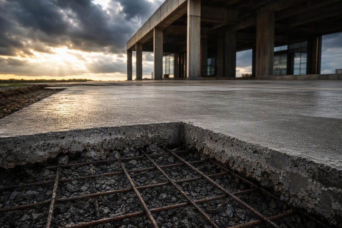
Quick-reference slab thicknesses by application
Scope and qualification: This is a general planning overview of published trade guidance, not a structural design standard. The figures below are preliminary rules of thumb—not universal minimums, structural calculations, equipment approvals, or evidence of code compliance. Local codes, permit requirements, equipment instructions, geotechnical findings, specifications, and structural drawings can override every range.
Slab thickness is the vertical depth of concrete from its finished top surface to the bottom of the concrete. It does not include the granular base, insulation, vapor retarder, topping, flooring, or supporting soil.
| Application | Preliminary thickness | Assumed loading | Escalate or obtain project-specific design when… |
|---|---|---|---|
| Patio, sidewalk, or walkway | About 4 in. | Foot traffic, ordinary furniture, and other light residential use | The slab will support a hot tub, masonry feature, outdoor kitchen, column, retaining element, vehicle, or another concentrated load |
| Residential driveway | Approximately 5–6 in. | Passenger cars and ordinary residential traffic on suitable support | Trucks, RVs, deliveries, repeated heavy traffic, weak edges, unstable soil, poor drainage, or severe exposure are expected |
| Ordinary garage floor | Approximately 4–5 in. | Parking passenger vehicles without unusual point loads | Vehicle lifts, machinery, jack stands, storage racks, heavy trucks, anchors, or workshop use are planned |
| RV, truck, workshop, or equipment area | Often begins around 6 in. | Heavier vehicles or more demanding use than an ordinary residential slab | Wheel, jack, post, anchor, machine, or dynamic loads are consequential; thickness alone does not establish vehicle-weight capacity |
| Commercial parking | Broadly 6–8 in. | General commercial traffic under assumed suitable support | Actual wheel and axle loads, traffic frequency, joints, support conditions, or edge loading have not been established |
| Industrial floor | No dependable universal range | Forklifts, racks, machinery, storage, and operational traffic | These floors should be analyzed from actual loads, support, joints, anchors, concrete properties, and serviceability requirements |
| Hot tub, vehicle lift, rack post, machinery, or structural anchor | Project-specific design or manufacturer criteria required | Concentrated, anchored, dynamic, or consequential loading | Always verify the footprint, anchorage, slab condition, concrete properties, support, edges, openings, joints, and reinforcement |
Published contractor guidance commonly puts light pedestrian slabs near 4 inches, residential driveways near 5–6 inches, and ordinary garage floors near 4–5 inches. These are examples of trade practice rather than validated design criteria; the cited guide itself says soil, subbase quality, loading, and reinforcement can change the result. See this contractor’s application-by-application thickness table.
Recommendations for driveways are not uniform. Some published guides use 4–5 inches, some identify 5 inches for light residential vehicle use, and others favor 5–6 inches. Guidance also often moves toward 6 inches for RVs, trucks, workshops, or repeated traffic. None of those figures proves that a slab can support a particular vehicle or machine.
Commercial numbers require still more caution. One commercial paving guide discusses 6–8 inches for parking lots and still broader ranges for industrial applications, while emphasizing traffic, soil bearing behavior, compaction, drainage, and expected loads as design inputs. Those figures are general recommendations, not a universal industrial specification or code rule (commercial concrete thickness guide).
Use the table by identifying the assumptions behind a provisional range and then looking for conditions that invalidate them. A 4-inch patio assumes light use and suitable support. A 5- or 6-inch driveway assumes more than nominal depth: it also depends on prepared support, drainage, suitable concrete, coordinated joints, and construction that achieves the specified thickness.
First identify the slab: ground-supported or suspended
Before choosing a thickness, identify how the slab carries load.
A slab on grade or slab on ground transfers loads into the soil and prepared materials beneath it. Patios, sidewalks, driveways, many garage floors, equipment pads, and many warehouse floors fall into this category. Their performance depends on the interaction of the concrete, support, joints, reinforcement, and loading.
A suspended slab spans between walls, beams, columns, or other structural supports. Elevated apartment floors, balconies, parking decks, and upper-level concrete floors are familiar examples. These slabs act as structural floors rather than surfaces continuously supported by the ground.
The familiar 4-, 5-, and 6-inch planning figures chiefly concern ordinary ground-supported work. They must not be transferred directly to an elevated floor. Preliminary sizing of a suspended slab may depend on:
- Slab system and load path
- Clear and effective span
- One-way or two-way action
- Support geometry and continuity
- Self-weight and other dead loads
- Occupancy, storage, vehicle, and other imposed loads
- Concentrated loads, openings, and penetrations
- Deflection and vibration limits
- Fire-resistance requirements
- Construction sequence and temporary support
- Reinforcement arrangement and cover
- Durability and environmental exposure
Increasing span generally increases the depth needed for stiffness and strength. Greater depth also adds self-weight, which becomes another load on the structure. One-way slabs, two-way slabs, and flat slabs can therefore require different depths at the same nominal span because their support arrangements and load paths differ.
One low-authority preliminary-sizing source illustrates this system dependence with 8-meter-span overall-depth ranges of 290–360 mm for its listed one-way slab, 210–275 mm for its two-way slab, and 250–400 mm for its flat slab. The same source omits the governing design code, material strengths, support geometry, and complete loading assumptions, and its tables contain internal inconsistencies. Its suspended-slab depth tables should therefore be read only as an illustration—not as a basis for drawings, pricing commitments, or construction.
It is also essential to distinguish effective depth from overall depth. Effective depth is a calculation dimension generally measured to reinforcement participating in resistance. Overall depth is the full concrete thickness and includes cover and other geometric allowances. A calculated effective depth cannot simply be relabeled as the overall slab depth.
For suspended work, the responsible question is not “Is 6 inches enough?” It is “What system, span, supports, loads, performance criteria, and governing requirements determine the necessary overall depth?”
The loads that actually control slab depth
Two objects with the same total weight can place very different demands on concrete.
A broadly distributed load spreads force over a relatively large area. A concentrated load applies force through a wheel, rack post, jack, column base, anchor group, or machine foot.
Total weight is only one input. A preliminary review should also consider:
- Contact area beneath each wheel, post, or plate
- Wheel, axle, post, and anchor spacing
- Static, moving, vibrating, or impact action
- Number and frequency of load applications
- Load duration and operating patterns
- Distance from an edge, corner, opening, penetration, or joint
- Nearby wheels or posts acting at the same time
- Load transfer across joints
- Concrete properties and existing condition
- Stiffness and continuity of ground support
Location can be decisive. An interior load surrounded by concrete does not behave like the same load at a free edge or corner. A wheel crossing a joint also creates a different condition from a stationary load near the center of a panel. Industrial guidance identifies load magnitude, dynamic behavior, traffic frequency, base-plate dimensions, soil conditions, and proximity to joints as relevant to slab-capacity analysis (industry overview of slab load capacity).
A single feature may therefore govern one part of an otherwise lightly loaded slab, including:
- A filled hot tub on a patio
- A masonry outdoor kitchen or fireplace
- A two-post vehicle lift in a garage
- A storage rack with small post plates
- A vibrating or impact-producing machine
- Stabilizer jacks on an RV or trailer
- A structural column or canopy post
- A heavily loaded anchor group
The solution is not necessarily to thicken the entire slab. Transitions, reinforcement, joints, and differential movement still require coordination.
Anchorage can independently control depth. A floor may be adequate for general traffic but too shallow for required anchor embedment, bottom clearance, edge distance, or reinforcement coordination. Lift and machinery planning should therefore begin with the equipment manufacturer’s criteria and continue with verification of the actual installation location.
For preliminary slab-on-grade analysis, assemble at least:
- Specified or measured concrete strength
- Proposed or measured slab thickness
- Magnitude of each concentrated load
- Wheel, post, or base-plate contact area
- Subgrade modulus or other support characterization
- Interior, edge, corner, opening, and joint locations
- Applicable factor of safety
- Joint layout and load-transfer assumptions
- Dowel information where relevant
- Temperature range and environmental effects
- Adjacent wheel or post loads
- Reinforcement assumptions
- Anchor geometry and clearances
A preliminary calculator may examine flexure, local bearing, punching shear, estimated crack width, shrinkage-and-temperature reinforcement, and joint-dowel bearing. The available slab-on-grade calculator for post or wheel loading explicitly limits itself to schematic understanding and depends on user-supplied assumptions. It cannot replace structural design.
What lies beneath the slab matters as much as its depth
A ground-supported slab does not act alone. Its performance depends on the continuity, stiffness, drainage, and stability of the material beneath it.
The subgrade is the natural or prepared soil at the bottom of the slab system. A subbase is a placed layer—often granular or treated—between the subgrade and the concrete. The terms are not interchangeable, and the appropriate materials and dimensions depend on the site and project design.
A thick slab over poorly compacted fill can still settle. Moisture-sensitive or expansive soils can change volume as water content changes.
Common support concerns include:
- Low or variable soil stiffness
- Inadequately compacted fill
- Organic or unsuitable material
- Expansive or moisture-sensitive soil
- Differential settlement
- Trenches and utility backfill
- Washout or erosion at edges
- Water trapped beneath or beside the slab
- Frost-related movement
- Abrupt transitions between natural soil and placed fill
Excavation, grading, compaction, drainage, and base preparation are parts of the slab system—not optional tasks added after thickness has been selected. The work should establish required elevations and falls, remove unsuitable material, compact specified layers, protect accepted subgrade from disturbance, and limit water accumulation.
Published contractor recommendations for granular-base depth vary and should not be treated as universal specifications. Base material, gradation, depth, compaction, and drainage should reflect the soil, excavation, loading, climate, and project documents. An arbitrary gravel layer cannot correct every weak-soil or groundwater problem.
Surface drainage, roof discharge, adjacent grades, groundwater, capillary moisture, and interior vapor-management needs may all affect the assembly.
Climate can also influence concrete properties and detailing. Freezing and thawing, deicing salts, wetting and drying, heat, and corrosive exposure may affect mixture requirements, protection, joints, cover, and maintenance. Added thickness alone does not make unsuitable concrete resistant to its environment.
Geotechnical input is prudent where soils are expansive, unstable, poorly documented, or prone to settlement; where uncontrolled fill or high groundwater is present; or where consequential loads depend on reliable support. Structural conclusions are only as dependable as the support assumptions behind them.
Reinforcement, joints, curling, and curing: what thickness cannot solve
Concrete can crack. Greater thickness does not guarantee a crack-free, settlement-free, or maintenance-free slab.
Available reinforcement categories include reinforcing bar, welded wire reinforcement or mesh, and fiber systems. Depending on the design, reinforcement may control crack widths, improve tensile behavior, maintain continuity across cracks, or help distribute forces. Its contribution depends on type, quantity, continuity, support, and vertical placement.
Reinforcement should not be treated as permission to reduce an otherwise necessary slab depth. It also cannot automatically compensate for deficient support, poor concrete, misplaced joints, inadequate anchorage, or faulty construction.
Joint terminology also matters:
These terms are not synonyms. Joint location, depth, timing, load transfer, sealing, and interaction with reinforcement should be coordinated for the actual slab. No universal spacing is appropriate for every concrete mixture, slab depth, panel geometry, reinforcement strategy, climate, and use.
If the slab loses full contact with its support, loading can create greater stress and movement than a fully supported model predicts. Poor load transfer at joints can also allow one panel edge to deflect relative to the next, which matters particularly for hard-wheeled traffic.
A modeled warehouse comparison shows why thickness cannot be evaluated in isolation. The study used a 172,800-square-foot facility, 9,600-pound rack-post loads, and a three-wheeled reach truck carrying 3,000 pounds on small hard wheels. It assumed a 5,800 psi subgrade resilient modulus, excluded seismic effects, and assigned materially different joint spacing, curling behavior, reinforcement, and load-transfer performance to the alternatives.
Under that particular model, the reported minimum alternatives were 10 inches for an unreinforced slab, 7 inches for a strategically reinforced alternative, and 5 inches for a shrinkage-compensated macrofiber alternative. The unreinforced alternative assumed less than 4% load-transfer efficiency at sawcut joints, while the strategically reinforced alternative targeted 90%. These were analytical results for one facility—not field trials or a universal industrial thickness ladder (modeled comparison and assumptions).
The lesson is not that 5 inches is generally better than 10 inches. It is that slab performance emerges from a system: thickness, reinforcement, joint quantity, load transfer, curling control, support, concrete properties, and traffic must work together.
Construction quality remains part of that system. The design must be translated into:
- Correct concrete properties and consistency
- Accurate forms, elevations, and slopes
- Reinforcement held at its intended position
- Coordinated penetrations and blockouts
- Appropriate placement and consolidation
- Finishing suited to use and exposure
- Protection from premature drying and adverse weather
- A curing plan appropriate to the specification
- Joint installation at the required locations and time
- Verification of uniform depth and local thickenings
No single curing duration, joint layout, reinforcement arrangement, or thickness can be promised to prevent failure in every project.
A practical selection workflow for common projects
A repeatable workflow is more defensible than selecting a number from a chart.
1. Identify the slab type
Confirm whether the slab is ground-supported or suspended. If it spans between structural supports, stop using patio and driveway rules of thumb and involve the structural designer.
2. List present and credible future uses
Record both the initial use and foreseeable changes, such as a future hot tub, larger vehicle, storage rack, lift, machine, masonry feature, or workshop conversion. These loads are easier to coordinate before placement than to investigate in an undocumented existing slab.
3. Classify every load
Separate pedestrian, distributed, vehicle, wheel, axle, post, dynamic, impact, vibrating, and anchored loads. Record contact areas and locations rather than relying only on gross weight.
4. Assess soil and drainage
Review available geotechnical information. Identify natural soil, fill, trenches, compaction requirements, groundwater, roof runoff, slopes, and potential settlement or moisture-related movement.
5. Review climate and exposure
Consider freezing and thawing, deicing salts, wetting, heat, chemical exposure, and interior moisture or vapor requirements. These conditions may change the concrete specification and detailing even when structural depth remains similar.
6. Select the structural concept
Decide whether the project needs a uniform slab, local thickening, equipment pad, grade beam, or separate footing. Coordinate reinforcement, joints, anchors, edges, openings, and transitions with that concept.
7. Check governing documentation
Reconcile local requirements, permits, structural drawings, geotechnical recommendations, specifications, and equipment-manufacturer instructions. If they conflict, obtain clarification from the responsible designer, manufacturer, or authority rather than choosing the most convenient figure.
Scenario 1: ordinary patio
Begin near the common 4-inch planning figure only where use is light and support is suitable. Ordinary furniture and pedestrian activity fit that assumption. A hot tub, masonry fireplace, outdoor kitchen, roof column, pergola post, retaining element, or vehicle does not.
For a concentrated feature, compare whole-patio thickening with a local foundation or thickened area. The appropriate solution depends on the footprint, load, soil, movement, and connection to the surrounding slab.
Scenario 2: passenger-car driveway
Begin with the commonly cited 5–6-inch range, recognizing that published trade sources disagree about whether 5 or 6 inches should be preferred. Then assess:
- Delivery and service-vehicle access
- Wheel and axle loading
- Number of vehicle passes
- Turning and braking areas
- Unsupported or vulnerable edges
- Soil movement and utility trenches
- Surface and subsurface drainage
- Freezing-and-thawing exposure
- Connections to the street, garage, or apron
A thicker driveway can still crack or settle if it bridges poorly compacted trench backfill or loses edge support.
Scenario 3: garage
Separate ordinary passenger-vehicle parking from workshop and equipment use. Jack stands, narrow casters, two-post lifts, machinery, rack posts, anchors, and heavy vehicles introduce concentrated conditions that ordinary 4–5-inch garage guidance does not resolve.
For a vehicle lift, obtain the manufacturer’s criteria for concrete strength, minimum depth, reinforcement, anchor type and embedment, edge distance, joint clearance, slab age, and condition. Then verify the proposed installation. A slab is not suitable merely because it looks intact or was described as a garage floor.
Scenario 4: RV pad or workshop
Treat 6 inches as a frequently cited starting point, not a guaranteed design. Published commercial guidance associates that depth with RVs, large trucks, machinery, and workshops while also identifying soil, drainage, reinforcement, and local requirements as relevant variables (4-inch versus 6-inch planning guide).
Investigate wheel locations, stabilizer jacks, machine feet, anchors, vibration, and likely future equipment. If only one zone has consequential loads, compare a uniform slab with a local thickened pad, grade beam, or separate footing.
Scenario 5: commercial or industrial floor
Replace the lookup table with actual analysis. Establish wheel loads, rack-post loads, base-plate dimensions, machinery actions, traffic paths, joint crossings, support properties, curling assumptions, anchors, and serviceability limits.
Operational details matter. Small hard wheels can be sensitive to differential movement at joints. Rack positions may conflict with sawcuts, while future aisle layouts may move traffic onto areas not originally intended for it. The floor design should reflect the operating plan, not merely the building’s occupancy label.
Pre-pour checklist
Before placement, confirm as applicable:
- Approved drawings and current revisions
- Permit and inspection requirements
- Accepted subgrade and base
- Required compaction and elevation records
- Surface and subsurface drainage
- Forms, slopes, edges, and local thickenings
- Embedded services, sleeves, blockouts, and penetrations
- Vapor-retarder, insulation, or thermal requirements
- Reinforcement type, laps, support, and vertical position
- Joint types, locations, details, and load-transfer provisions
- Concrete specification and exposure requirements
- Placement, finishing, protection, and curing plan
- Anchor templates and equipment coordination
- Method for checking thickness during placement
- Responsibility for resolving field changes
This review provides an important opportunity to identify omitted thickenings, misplaced joints, unsupported reinforcement, drainage conflicts, or future anchor zones before correction becomes more disruptive.
Concrete quantity changes when thickness changes
Concrete quantity estimation is separate from structural sizing. A volume calculation shows how much concrete a geometric slab contains; it does not establish whether that slab can carry its loads.
The basic formula is:
Volume = length × width × thickness
All dimensions must use compatible units. For a slab measured in feet with thickness measured in inches:
Cubic feet = length (ft) × width (ft) × thickness (in.) ÷ 12
Convert cubic feet to cubic yards by dividing by 27:
Cubic yards = cubic feet ÷ 27
These standard volume conversions are also summarized in this concrete slab type and quantity overview.
Every additional inch over 100 square feet adds:
100 × 1 ÷ 12 = 8.33 cubic feet8.33 ÷ 27 = approximately 0.31 cubic yard
That is the geometric increase before ordering allowances, irregular excavation, overbreak, form movement, and construction tolerances.
For a 20-by-20-foot slab, the plan area is 400 square feet:
| Nominal thickness | Calculation | Geometric volume |
|---|---|---|
| 4 in. | 20 × 20 × 4 ÷ 12 ÷ 27 |
Approximately 4.94 yd³ |
| 5 in. | 20 × 20 × 5 ÷ 12 ÷ 27 |
Approximately 6.17 yd³ |
| 6 in. | 20 × 20 × 6 ÷ 12 ÷ 27 |
Approximately 7.41 yd³ |
These figures are before any ordering allowance. There is no universal waste percentage or cost per cubic yard because excavation accuracy, geometry, access, supplier practices, order size, location, and market conditions vary.
Calculate local thickening separately. First determine the volume of the uniform base slab. Then calculate only the additional depth in each thickened zone, grade beam, or pad. If a zone is 10 inches overall within a 5-inch slab, its supplemental volume is based on the extra 5 inches rather than the full 10 inches.
How to determine the thickness of an existing slab
Existing-slab assessment should begin with the least intrusive evidence and become more invasive only when necessary.
- Review current or archived structural and architectural drawings.
- Ask the owner, architect, general contractor, structural engineer, or original concrete contractor.
- Review placement records, inspection reports, photographs, and equipment documentation.
- Inspect any safely exposed slab edge, utility trench, drain opening, or authorized existing penetration.
- If records and visible evidence are insufficient, engage a qualified consultant to select a testing method.
- Consider destructive investigation only after concealed hazards have been located and the work has been authorized.
A nominal depth shown on drawings does not prove that an existing slab has that exact thickness everywhere.
Consultant-led nondestructive methods named in published manufacturer guidance include:
- Impact-echo
- Ultrasonic pulse-echo
- Ground-penetrating radar
- Magnetic Imaging Tomography
The available evidence does not establish comparative accuracy, cost, depth limits, or suitability for those technologies. Reinforcement congestion, access, moisture, surface condition, geometry, and the information sought may affect selection. A qualified consultant should choose and interpret the method. The options are summarized in Wagner Meters’ guide to determining existing slab thickness.
A drilled-hole wire probe is a destructive measurement technique, not an unsupervised recommendation. The cited guide describes drilling but does not provide a complete concealed-hazard locating or cutting-safety procedure. Do not treat that description as authorization to drill or core. Before intrusive work, the project team should locate post-tensioning tendons, reinforcement, electrical services, plumbing, radiant heating, communications, and other concealed systems, and obtain appropriate authorization and controls.
Thickness alone cannot qualify an existing slab for a vehicle lift, machine, rack, column, or structural load. Other unknowns may include:
- Concrete strength and deterioration
- Reinforcement type, quantity, continuity, and position
- Joint locations and load transfer
- Subgrade support and settlement history
- Cracks, curling, repairs, and previous penetrations
- Actual edge and opening distances
- Anchor interference and embedment
- Load location and contact area
- Local thickening or concealed foundations
Moisture testing is another reason slab depth may matter. The cited ASTM F2170-related manufacturer guidance places in-situ relative-humidity sensors at 40% of slab depth when drying from one side and 20% when drying from two sides. Correct sensor position therefore depends on knowing both slab thickness and drying conditions.
Professional evaluation is warranted when the result affects structural safety, equipment anchorage, a flooring warranty, post-tensioned construction, or another consequential load. The objective is not merely to obtain a dimension; it is to establish enough reliable information to evaluate the proposed use.
Is a 4-inch concrete slab thick enough for a driveway?
It may be used in some residential work, but 4 inches should not be assumed adequate for every driveway. Published trade guidance varies, with examples ranging from 4–5 inches to 5–6 inches. One contractor guide identifies 5 inches for light residential driveway use and 6 inches for RVs, trailers, and heavier traffic (4-, 5-, and 6-inch trade guidance).
For early planning, 5–6 inches is a commonly cited range for passenger-vehicle driveways. Final depth should reflect wheel and axle loads, traffic frequency, edge support, soil, drainage, exposure, project documents, and local requirements.
Can rebar or wire mesh allow a thinner concrete slab?
Not automatically. Rebar, welded wire reinforcement, and fibers may control crack widths, improve tensile behavior, or help distribute loads when properly designed and placed. They do not make weak support, deficient joints, inadequate anchorage, poor drainage, or insufficient depth acceptable.
A project-specific industrial analysis may justify a different depth through coordinated reinforcement, joint behavior, and curling control. That does not create a general rule that adding mesh or rebar permits one inch less concrete.
How thick should concrete be for a two-post vehicle lift?
There is no universal thickness for every two-post lift. Use the lift manufacturer’s requirements for slab depth, concrete strength, reinforcement, anchors, embedment, edge distance, joint clearance, slab age, and condition. Then verify that the actual slab meets those criteria at the proposed post locations.
Generic garage-floor guidance is not sufficient for lift approval. If thickness, strength, reinforcement, support, or concealed systems are unknown, arrange professional investigation before installation or drilling.
Should a hot tub or heavy machine sit on a thicker section of slab?
Possibly, but the correct solution depends on operating weight, footprint, vibration, soil, anchors, joints, and surrounding construction. A local thickened zone, dedicated pad, grade beam, or separate footing may be more suitable than thickening the entire slab.
Treat the feature as a concentrated load. Do not assign a universal thickness from total weight alone or assume that an ordinary patio or garage slab is adequate.
How can I measure an existing concrete slab without drilling it?
Begin with drawings, placement records, archived documents, safely exposed edges, and existing openings. If those sources are inconclusive, a qualified consultant may consider impact-echo, ultrasonic pulse-echo, ground-penetrating radar, or Magnetic Imaging Tomography.
Method selection depends on the slab, access, embedded materials, surface condition, and required information. Nondestructive thickness measurement also does not establish full load capacity; concrete strength, reinforcement, support, joints, anchors, and condition may still require investigation.
The defensible approach to concrete slab thickness is to replace the search for one standard number with a repeatable decision. Identify whether the slab is ground-supported or suspended, define distributed and concentrated loads, evaluate support and water conditions, coordinate reinforcement and joints, and verify applicable requirements and equipment criteria.
About 4 inches may be a reasonable planning point for a light pedestrian slab, while 5–6 inches is common preliminary trade guidance for residential vehicle slabs. Consequential loads, uncertain soil, structural anchors, industrial traffic, suspended construction, and alterations to existing slabs require project-specific review.