
Concrete Control Joints: Plan the Crack Before the Pour
Plan concrete control joints with practical spacing and depth examples, saw-cut timing, panel-layout rules and coordination details for slabs on ground.
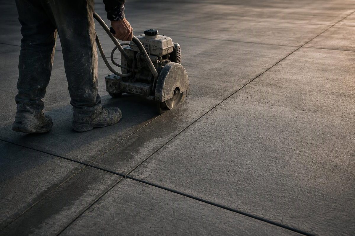
Concrete control joints—technically contraction joints—create weakened planes that encourage shrinkage cracks to form along planned lines rather than randomly across a slab. They control the location of cracking; they do not guarantee crack-free concrete. As concrete cools and shrinks, restraint can produce tensile stresses greater than the concrete can resist. A properly formed groove gives the resulting crack a preferred path. NRMCA’s CIP 6 explains this mechanism.
For ordinary concrete slabs on ground, three decisions work together: joint spacing, groove depth and installation timing. These flatwork guidelines are not a jointing prescription for suspended floors, post-tensioned slabs or structural foundations.
Control, isolation and construction joints are different
Use separate drawing symbols and details for these three functions:
- Control/contraction joint: A partial-depth groove, formed or cut into the slab, that encourages a crack below it.
- Isolation joint: A full-depth separation allowing independent movement between the slab and adjoining elements, such as columns or walls that do not require lateral restraint from the slab. Compressible joint material keeps the concrete elements apart.
- Construction joint: The interface between successive concrete placements. Its detail must address whether movement, load transfer or structural continuity is required.
A saw cut is not a substitute for full-depth isolation. Likewise, a pour break does not automatically provide the intended contraction-joint behavior. ACI 302.1R-15, Chapter 5 distinguishes these joint types and assigns their layout and detailing to the designer.
Spacing: relate the grid to slab thickness
NRMCA recommends maximum contraction-joint spacing of 24–36 times the slab thickness, with an additional recommended limit of 15 feet. Keep the units consistent when calculating: a 4-inch slab multiplied by 24–36 gives 96–144 inches, or 8–12 feet. Its practical example is approximately 10-foot spacing. NRMCA CIP 6
The following values apply that guidance; they are starting points for a layout, not a structural design. The spacing range represents choices for the recommended maximum, not a minimum distance between joints.
| Slab thickness | Calculated maximum spacing at 24–36 × thickness, capped at 15 ft | General minimum groove depth* |
|---|---|---|
| 4 in. | 8–12 ft | 1 in. |
| 5 in. | 10–15 ft | 1¼ in. |
| 6 in. | 12–15 ft | 1½ in. |
Depths use NRMCA’s general rule of one-quarter of slab thickness, but not less than 1 inch. Early-entry sawing has separate guidance below.
The upper end is not automatically the right choice. ACI identifies reinforcement, concrete shrinkage potential, base friction, restraints, discontinuities and environmental conditions as factors in selecting spacing. Slab thickness itself must first be established for the intended use and loading; see concrete slab thickness by use and load.
Layout: make compact panels, not just parallel cuts
Aim for square panels. Both NRMCA and ACI recommend a maximum panel length-to-width ratio of 1.5:1 for ordinary flatwork; ACI prefers 1:1, calls for continuous rather than staggered contraction joints, and advises avoiding L- and T-shaped panels. ACI joint-layout guidance
For example, a simple, unobstructed 20-by-30-foot slab could be divided into six 10-by-10-foot panels. That illustrates spacing and proportion together; it is not a universal layout for a slab containing columns, pits or thickened areas.
Place those interruptions on the plan before drawing the grid. NRMCA recommends that contraction joints intersect column-isolation openings. Where a square isolation opening surrounds a column, turning it 45 degrees allows the approaching joints to meet its corners. NRMCA column detail
Depth and timing: establish the weak plane early
A shallow decorative score should not be treated as an effective control joint. Under NRMCA’s general guidance, the groove should reach at least one-quarter of slab thickness and never less than 1 inch.
The cutting window depends on the method:
- Tooled joints: Form them early during finishing and rerun them later to ensure the groove has not bonded back together.
- Conventional saw cuts: NRMCA gives a typical window of 4–12 hours after finishing.
- Early-entry dry cuts: NRMCA gives 1–4 hours after finishing, depending on setting characteristics, with a minimum depth of 1 inch. These cuts are typically shallower than conventional cuts; use the specified early-entry method and depth rather than assuming the general quarter-depth rule is interchangeable.
These are guidance windows, not fixed appointments. Cutting too early can cause raveling, or tearing of the joint edges; waiting too long risks uncontrolled cracking before the weakened plane is established. NRMCA cutting guidance
What the drawings and pre-pour meeting should settle
Document the joint locations, type, depth, cutting method and timing before placement—not simply “provide control joints.” Coordinate the saw depth with reinforcement and embedded services.
Reinforcement crossing a joint is a design decision, not a field improvisation. ACI advises against continuing deformed bars across contraction joints because they restrain opening, unless properly designed as an enhanced aggregate-interlock load-transfer mechanism. Where positive load transfer is needed, designed dowels or other devices may be required. Do not cut or discontinue reinforcement without the designer’s detail. ACI reinforcement and load-transfer guidance
Specify the joint treatment for the exposure. ACI recommends semi-rigid filler to protect edges under hard-wheeled material-handling traffic, while wet or hygienic conditions call for elastomeric sealing. Where both conditions apply, sealing alone does not settle edge protection: ACI advises considering alternative means of armoring the joint edges. ACI joint-filling guidance
Also coordinate topping and flooring details: topping-slab joints should align with base-slab joints, and the design should address joints telegraphing through finishes. Those choices belong with the slab detail, not as an afterthought once the floor finish is selected. ACI topping and flooring guidance