
When Slab Piers Fit a Settled Concrete Floor
Learn when slab piers suit a settled concrete floor, how push and helical systems differ, and what engineers should verify before installation.
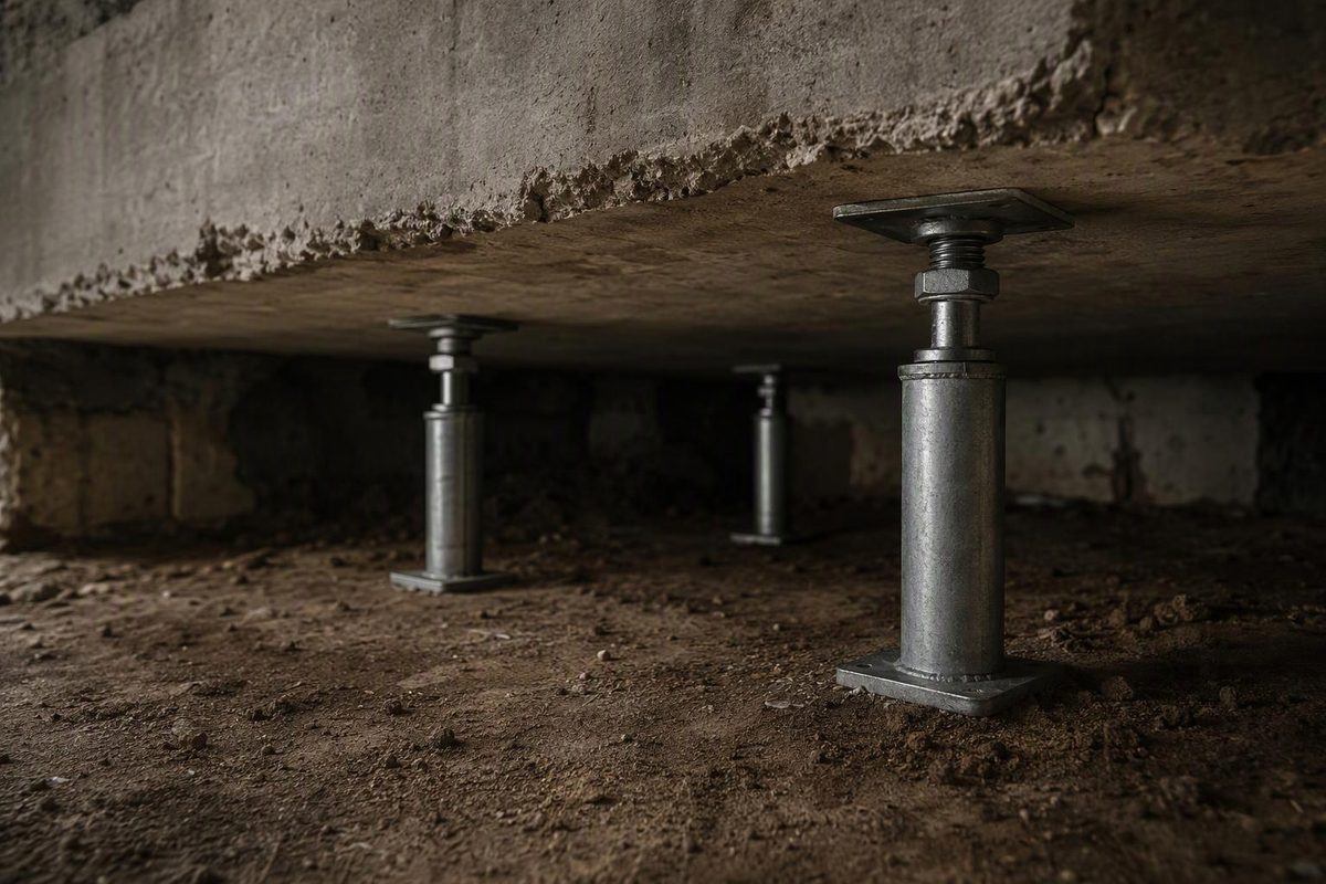
Slab piers can stabilize a settled concrete floor when shallow soil support is unreliable and the load must be transferred to deeper bearing soil or rock. They are not a general crack repair: the existing slab must be strong enough to deliver loads into discrete brackets, and the cause of movement must be diagnosed before a system is selected.
A slab pier is a small-diameter steel pile installed through an existing floor. A bracket bears against the slab’s underside and connects it to the pier. This differs from perimeter underpinning, which supports a footing or grade beam carrying walls and columns, and from slabjacking, which injects grout or polyurethane beneath a slab without establishing the same deep load path.
Choose the observed movement, affected element and support condition to identify the repair path that warrants evaluation.
Slab Repair Path
This screen identifies the repair category to investigate; it does not size or specify a pier.
Basis: ACI 302.1R-15 and the cited ICC-ES and manufacturer documents. Product capacity does not establish slab adequacy, spacing or local permit requirements.
Slab Piers Create a Discrete Support System
A conventional slab-on-ground distributes its load into the base and subgrade. The American Concrete Institute states that slab performance depends on the integrity of this soil-support system. It identifies slab thickness, reinforcement, joints, base preparation and loads among the items construction documents should address (ACI 302.1R-15).
After settlement creates a void, part of the slab may bridge between the remaining contact points. Cracks, rocking joints and localized deflection can follow. A slab-pier repair changes the load path to:
floor load → concrete slab → underside bracket → steel pier → bearing stratum
The slab must then transfer load to discrete brackets. Pier capacity alone is not enough. The designer also has to consider slab thickness and condition, reinforcement, bracket bearing, punching shear and bending between supports.
One current slab-pier specification illustrates that distinction. It lists a 15,000 lb mechanical-system capacity but directs users to check local punching shear and slab strength separately (Supportworks PP288 specification). An advertised capacity per pier therefore cannot establish spacing by itself. The existing concrete may govern the layout.
Push And Helical Piers Use Different Installation Reactions
“Slab pier” describes the application and bracket arrangement, not one universal pile type.
| System | How It Advances | Main Constraint |
|---|---|---|
| Push pier | Hydraulic equipment advances coupled steel tubes | The slab supplies reaction and must not be overstressed |
| Helical pier | A motor rotates a shaft with one or more helix plates | Shaft, helices, torque and soil profile must suit the load |
For a push system, the crew places a bracket beneath the slab and hydraulically advances tube sections through it. A Supportworks manual describes driving to the target ultimate pressure or load, or until the structure begins to mobilize. It recommends slower electric pumps for slab-pier work because their lower flow gives greater control and reduces the potential to overstress the concrete during sudden load increases (Supportworks technical manual).
A helical pile is screwed into the ground and extended until it reaches the required depth or bearing condition. A current ICC-ES report describes a typical system as a lead shaft with one or more helix plates, extension shafts, couplings and a bracket connecting the pile to supported concrete. The report requires project-specific engineering and verification that the connected concrete is adequate (ICC-ES ESR-3982).
Neither mechanism is universally preferable. Selection depends on the slab’s available reaction and strength, subsurface profile, groundwater, obstructions, headroom, corrosion exposure, loads and the evaluated components available for the proposed system.
Confirm Settlement Before Specifying Piers
Slab piers are most relevant when an interior slab has settled because shallow support is unreliable and the repair needs to transfer load deeper. They are not an automatic response to every crack.
Drying shrinkage and curling can crack concrete without establishing soil settlement. ACI states that present technology can reduce cracking and curling but cannot eliminate them, and that some cracking does not necessarily indicate inadequate design or poor construction (ACI 302.1R-15). Elevation measurements, crack and joint behavior, plumbing conditions and subsurface information should establish whether the slab is moving and why.
The diagnosis may point to another repair:
- Slabjacking or void filling can restore shallow contact and may lift a settled slab, but it does not create the same deep load path as a pier.
- Removal and replacement allows unsuitable fill, drainage defects or buried organic material to be corrected and may be more rational for extensively fractured concrete.
- Perimeter underpinning addresses a settled load-bearing footing or grade beam. Interior slab piers do not automatically stabilize either element.
- Drainage or plumbing repair may still be necessary. A pier can support the floor without stopping erosion, leakage or moisture migration.
The floor’s load also matters. A lightly loaded panel is not the same problem as a slab supporting partitions, storage racks or equipment. Confirm the existing slab thickness and loading rather than assuming a nominal residential thickness.
Installation Requires Coring And Underslab Access
A typical push-pier installation follows this sequence:
- Survey floor elevations and lay out pier locations.
- Locate utilities, reinforcement and any post-tensioning tendons.
- Core an access hole through the slab.
- Excavate enough subgrade to seat the bracket against the slab’s underside.
- Advance the pier to the engineered termination criterion.
- Stabilize the slab at its present elevation or connect multiple cylinders for a controlled lift.
- Lock off the system, fill remaining under-slab voids as specified and patch the access holes.
Access dimensions are product-specific. The PP288 system uses an 8-inch core, while Earth Contact Products lists 7- to 8-inch access holes for two of its slab systems (Supportworks; Earth Contact Products). Neither dimension is a universal rule.
Stabilization and lifting are different scopes. Stabilization transfers load at approximately the existing elevation. Lifting attempts to recover elevation and can change crack widths, door clearances, partition loads, plumbing slopes and interfaces with fixed perimeter construction.
In a monolithic slab foundation, concealed services and integrated thickened elements make the survey before coring especially important. Post-tensioning tendons, radiant tubes, drains and electrical work must be located rather than inferred from a standard floor layout.
Repair Drawings Must Address The Slab And Pier
A repair plan should contain more than dots labeled “piers.” It should document:
- surveyed elevations and the intended stabilization or lift limits;
- slab thickness, reinforcement, joints and known cracks;
- walls, columns, equipment and other loads in the affected area;
- pier type, shaft and bracket model, finish and applicable evaluated capacity;
- design service load at each pier and the governing slab checks;
- pier spacing, edge distances and treatment at cracks or joints;
- required depth or bearing condition and the hydraulic-pressure or torque criterion;
- maximum driving force and permitted incremental lift;
- utility, drain, radiant-tube and post-tensioning exclusions;
- void-fill material and sequence;
- core-patch and floor-finish restoration; and
- installation logs, elevation readings and inspection hold points.
The completed record should identify each pier and report its location, final depth, termination pressure or torque, lock-off load and measured lift.
In one current push-pier evaluation, ICC-ES requires construction documents and calculations plus inspection records covering actual depth, tip elevation, installation pressure and pier position. The report also states that the adequacy of the supported concrete must be justified separately (ICC-ES ESR-5005). Those requirements apply to that evaluated product, but they show why a catalog rating is not a complete repair design.
Permit Requirements Depend On The Jurisdiction
Permit and inspection rules are local. McKinney, Texas, for example, treats leveling and pier work as foundation repair and requires a permit, an engineer’s letter and drawings, followed by a final engineer’s report (City of McKinney foundation-repair guidelines). That procedure does not establish the rule elsewhere, so the local building department should be consulted before demolition or coring.
A credible proposal should identify the failed support condition, define the new load path and demonstrate that both the deep element and the existing slab between brackets can carry the resulting forces.