
When a One-Pour Foundation Works—and What Must Be Settled Before Concrete Arrives
Relocating a bathroom, repairing a concealed drain, or adding a floor outlet may require cutting and restoring concrete.
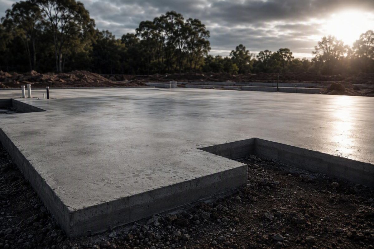
A monolithic concrete slab foundation combines the floor slab and its thickened load-bearing zones in one concrete placement. That integration can reduce forming stages, deliveries, pumping visits, and scheduling handoffs compared with foundations built through separate footing, wall, and floor placements. It does not turn the foundation into a simple, uniformly thick concrete pad.
Success depends on decisions made before the concrete arrives: how the building will bear on the soil or engineered base, where water will go, what finished-floor elevation is needed, how frost and soil gases will be addressed, where utilities and reinforcement belong, and which inspections or approvals must occur while the work remains visible.
This article is a selection and coordination overview, not a construction specification. Dimensions and assemblies are illustrative. Approved drawings, project specifications, product instructions, site-specific engineering, formal inspections, and locally adopted requirements govern the work.
What a monolithic slab is—and what the term does not mean
A monolithic slab is an integrated concrete foundation in which the floor and thickened perimeter or interior bearing zones are placed together. The thinner central portion commonly serves as the finished floor or subfloor. Deeper concrete at the edges, beneath bearing walls, or around concentrated loads distributes structural loads into the supporting soil or engineered base.
The conceptual load path is straightforward:
- Roof, wall, floor, equipment, and occupancy loads enter the walls or columns.
- The walls or columns transfer those loads to thickened concrete zones.
- The thickened zones spread the loads into the supporting material.
- The central slab carries its floor loads according to the project design.
“One pour” describes the placement sequence, not a uniform cross-section. A monolithic foundation may be considerably deeper around its perimeter, beneath an interior bearing line, or at a concentrated load than it is at the center of a room.
A conceptual cross-section
From the ground upward, a project-specific assembly may contain:
- Suitable native soil or approved fill
- A corrected and verified subgrade
- Compacted aggregate where specified
- Drainage, termite, or soil-gas components where required
- A continuous vapor-control layer with detailed seams and penetrations
- Project-specific under-slab or perimeter insulation
- Plumbing, conduit, sleeves, or radiant tubing
- Reinforcement held at its designed position
- A thinner central floor slab
- Thickened perimeter and interior bearing zones
- Anchors, hold-downs, embeds, and transitions to the structure above
The order of these components can vary. Aggregate, insulation, vapor control, and other layers must be coordinated with the structural, thermal, moisture, and product requirements for the particular project. A generic illustration should not override the approved foundation section.
Terminology matters
- Monolithic thickened-edge slab: The floor and its thickened load-bearing zones are placed as one integrated concrete element.
- Stem-wall slab: Footings and perimeter walls are built first; the interior floor slab is placed later.
- Floating slab: Commercial sources use this term inconsistently. It may refer to a ground-supported slab structurally separate from perimeter footings or to a lightly loaded slab without conventional deep foundations. The drawings must define the intended support.
- Combined footing-and-stem-wall pour: The footing and vertical foundation wall may be placed together, followed by a separate floor slab. Although that placement may be called “monolithic,” it is not the same as placing a thickened-edge foundation and floor together.
- Slab-on-grade: A broad description of a slab supported at or near ground level. Some publishers use it as a synonym for a monolithic slab; others apply it to slabs associated with separately constructed footings or stem walls.
The Certified Commercial Property Inspectors Association distinguishes monolithic and stem-wall construction primarily by sequence: reinforcement is installed before a monolithic slab is placed, whereas stem-wall construction uses separate footings and walls before the floor slab. Its guidance also emphasizes that concealed reinforcement and base conditions generally cannot be evaluated visually after construction. The article concerns commercial-property inspection, so residential design and inspection requirements may differ (CCPIA’s overview of monolithic and stem-wall foundations).
Illustrative dimensions—not design instructions
Commercial publishers commonly use broad residential examples to explain the difference between a central slab and a thickened bearing zone. These figures are not code requirements or evidence that a section is adequate for a particular building.
| Foundation component | Published commercial example | Appropriate use of the number |
|---|---|---|
| Central residential slab | 4–6 inches | Early visualization or preliminary estimating only |
| Thickened perimeter or bearing zone | 12–18 inches total thickness in one commercial description | Conceptual contrast with the central slab only |
| Aggregate base | Varies by assembly | Follow the approved grading, structural, drainage, and compaction requirements |
| Reinforcement | Rebar, welded wire, or a project-specific combination | Size, spacing, laps, cover, and supports require design information |
The cited 4- to 6-inch central slab and 12- to 18-inch bearing-zone examples come from a commercial foundation contractor that also acknowledges that reinforcement and trench requirements vary with local rules and project conditions (American Dry’s illustrative dimensions). Actual slab thickness, bearing-zone geometry, excavation depth, reinforcement, anchor details, and allowable soil pressure must come from the approved project documents.
Monolithic slab versus stem wall, crawl space, basement, and floating slab
Foundation selection is not a contest to identify the universally strongest system. Performance depends on the relationship among site conditions, structural design, drainage, construction quality, building use, and maintenance. A useful comparison asks what each system provides and what conditions it must accommodate.
| Consideration | Monolithic thickened-edge slab | Stem-wall slab | Crawl space | Basement | Floating slab* |
|---|---|---|---|---|---|
| Basic sequence | Bearing zones and floor are placed together | Footings and perimeter walls precede the floor slab | Footings, walls, or piers create underfloor space | Footings, tall walls, drainage work, and a lower floor create usable depth | Meaning depends on the drawings and local usage |
| Concrete work | Often one principal foundation placement | Usually multiple placements or masonry stages | Usually multiple stages | Usually multiple stages | Often one slab placement, though separate support may exist |
| Excavation | Can be limited on favorable sites | May require more excavation or forming to establish wall height | Enough to form supports and useful clearance | Substantial excavation | Often limited for small or lightly loaded uses |
| Finished-floor elevation | Commonly close to grade | Can be raised using perimeter walls and controlled fill | Naturally elevated | Main floor is elevated above the lower level | Usually close to grade |
| Slope or variable fill | Requires dependable support across the footprint | Can adapt by carrying walls to suitable bearing | Can adapt through walls, piers, or stepped supports | Can suit slopes but adds excavation and water-control demands | Generally associated with simpler sites and uses |
| Utility access | Limited after placement | Limited below the slab | Accessible from below | Accessible through the lower level or ceiling | Limited |
| Storage or lower-level space | None below the floor | None unless incorporated into another system | Limited service or storage potential | Significant potential space | None |
| Future plumbing changes | Potentially disruptive | Potentially disruptive where services are under concrete | Usually more flexible | Usually more flexible | Potentially disruptive |
| Main coordination concern | Concealed work must be resolved before placement | Interfaces among footing, wall, fill, and slab | Moisture, access, pests, and enclosure strategy | Excavation, drainage, moisture control, structure, and cost | Definition, edge support, loading, and acceptance |
*“Floating slab” has no single dependable commercial definition. Contract drawings should establish how the slab is supported and whether it is structurally connected to other foundation elements.
A conventional stem-wall system establishes footings and perimeter walls before the interior floor slab. That arrangement can raise the floor, retain fill, or carry support through changing grades. A monolithic slab integrates its thickened support zones with the floor placement.
One Florida builder describes favoring stem walls on lots requiring fill to reach the desired floor elevation while considering monolithic slabs on level, compacted sites needing little fill. That is regional builder experience rather than a universal engineering rule, but it illustrates why elevation and fill should be evaluated before selecting a system (Sposen Homes’ comparison of stem-wall and monolithic foundations).
Crawl spaces and basements provide accessible space beneath the occupied floor. That space can accommodate drains, water lines, wiring, ducts, inspections, and later alterations. A basement may also add storage or occupied area. Those benefits come with additional structure, excavation, access, drainage, moisture management, and enclosure work.
A slab offers a different package. Its direct ground-level floor can support near-grade entry and eliminate a separate framed ground floor, but services beneath or within the concrete are less accessible. Relocating a bathroom, repairing a concealed drain, or adding a floor outlet may require cutting and restoring concrete.
A total-project comparison should therefore consider:
- Excavation, disposal, and dewatering
- Soil correction, fill, compaction, and testing
- Foundation and floor construction
- Required finished-floor elevation
- Surface drainage and flood-related constraints
- Thermal, moisture, termite, and soil-gas details
- Utility installation and future access
- Storage or usable lower-level space
- Stairs, ramps, and accessible routes
- Local labor, equipment, and scheduling
- Long-term renovation flexibility
Comparing only the price or number of concrete placements produces an incomplete answer.
Site suitability: soil, fill, slope, frost, drainage, and flood elevation
A monolithic slab is generally easier to coordinate where the footprint can be supported consistently. A relatively level site with suitable native soil—or fill placed and verified under the project’s approved requirements—presents fewer complications than a steep lot, unstable ground, or a pad requiring deep and variable fill.
That does not make every level site suitable or every sloping site unsuitable. The central question is how the foundation loads will reach dependable support while accounting for water, soil movement, frost, and the required building elevation.
Site decision checklist
Before selecting the system, ask the project team to establish:
- Bearing material: What soil or engineered base will support the thickened zones?
- Soil behavior: Is the site known or suspected to contain expansive, collapsible, organic, erodible, weak, or frost-susceptible material?
- Existing fill: Is its origin, depth, and placement documented?
- Imported fill: How much is anticipated, where will it be deepest, and what acceptance process will apply?
- Slope: Can the footprint be supported without abrupt or inadequately supported transitions?
- Finished-floor elevation: How high must the floor sit relative to surrounding grade, drainage routes, and any applicable flood criteria?
- Groundwater: Could seasonal water affect excavation, soil strength, drainage, or under-slab moisture?
- Surface drainage: Where will roof water and site runoff discharge?
- Frost: What locally applicable frost criteria and design assumptions apply?
- Loads: Are there masonry walls, columns, tall walls, vehicles, equipment, or other concentrated demands?
- Building program: Does the owner need a basement, accessible service zone, or substantial future utility flexibility?
- Local hazards: Which soil-gas, termite, flood, wind, or seismic considerations need to be addressed by the design team?
Inadequately compacted or eroded support can leave voids beneath a slab and contribute to cracking, sagging, or settlement. The relevant condition is not simply whether fill exists, but whether the complete support system—from native soil through placed materials—matches the design assumptions. Foundation-repair guidance identifies erosion, inadequate compaction, and resulting voids as possible contributors to slab movement, though diagnosis and repair remain site-specific (Acculevel’s discussion of slab types and support loss).
Frost is a design condition, not a climate label
A monolithic slab can be used in some freezing climates, but “monolithic” does not identify the frost-protection strategy. Depending on the project, that strategy may involve the location of bearing elements, insulation, drainage, suitable material, heated-building assumptions, or another engineered arrangement.
Without authoritative project-specific design information, a generic perimeter-insulation detail should not be copied from another building.
Finished-floor elevation has two sides
Keeping the floor close to grade can provide convenient entry with few or no steps. A low floor can also leave less vertical separation from runoff, splashback, soil, mulch, paving, or floodwater. The project team should reconcile door thresholds, accessible routes, exterior paving, landscaping, drainage paths, and final grade before fixing the slab elevation.
Specialized geotechnical or structural input may be appropriate when the project involves:
- Uncertain soil or undocumented fill
- Expansive, weak, organic, collapsible, or visibly moving ground
- Substantial or variable fill
- Erosion, slumping, cracking, or other site instability
- High or fluctuating groundwater
- Significant elevation changes across the footprint
- Heavy or concentrated loads
- Unusual building geometry
- A frost-protection approach not already established in the approved documents
The owner should also ask the design and permitting team which locally adopted requirements govern frost, flood elevation, soil reporting, termite protection, radon or other soil gases, inspections, and energy performance. Requirements vary by jurisdiction; a regional blog or generic online detail cannot establish compliance for a parcel.
Construction sequence from subgrade to curing
Because the slab and its support zones are placed together, the entire footprint must be coordinated before concrete placement. The following sequence identifies typical decision points, not universal field instructions. The contractor, engineer, geotechnical professional, testing agency, product manufacturers, and building official retain their respective responsibilities under the project documents and local procedures.
1. Evaluate the site and lay out the building
The project team should reconcile property controls, building corners, structural grids, finished-floor elevation, drainage elevations, wall lines, and openings. A layout error can misplace both the floor edge and the thickened foundation beneath a wall or column.
2. Identify unsuitable or disturbed material
Vegetation, topsoil, organic material, debris, soft areas, or standing water may be incompatible with the approved support assumptions. The responsible project professional should determine what requires removal, correction, or further evaluation rather than allowing questionable conditions to be concealed.
3. Establish the bearing geometry
The excavation and forms create the perimeter thickening, interior bearing zones, column pads, depressions, and other designed features. If field conditions differ from the drawings—or excavation extends beyond the intended geometry—the project team should obtain direction before covering the condition.
4. Prepare and verify the subgrade
The approved documents may call for proofing, moisture conditioning, compaction, replacement, or testing. Where tests or observations are required, acceptance should come from the party identified in the project requirements rather than from appearance alone. General concrete guidance associates uneven or poorly compacted subgrade with voids and stress concentrations that can contribute to cracking (Deslauriers’ overview of common concrete-construction errors).
5. Place the specified aggregate base
Depth, gradation, compaction, and position within the assembly vary, so there is no universal aggregate recipe for every soil and slab.
6. Coordinate under-slab services
The project drawings may include drains, water services, conduit, sleeves, cleanouts, grounding components, floor boxes, or radiant tubing. Before concealment, the responsible trades should confirm locations, elevations, protection, and any tests required by their specifications, permits, or inspection procedures.
7. Complete environmental and thermal details
Where applicable, this stage may include vapor control, insulation, soil-gas components, termite details, drainage features, and transitions at slab edges or penetrations. Product-specific installation instructions and the approved details should govern.
8. Set forms, reinforcement, anchors, and embeds
Rebar or welded-wire reinforcement must be held at the location shown in the design. Steel left on the ground cannot be assumed to move to—and remain at—the required elevation during placement. Chairs, spacers, or other specified supports help maintain position.
Reinforcement provides tensile resistance and influences crack behavior; it does not make concrete crack-proof. Size, spacing, continuity, laps, cover, and anchorage matter in addition to the mere presence of steel.
9. Complete required pre-pour observations and inspections
Before placement, the parties responsible under the permit, contract, and design documents should have an opportunity to observe the work that concrete will conceal. An owner’s checklist can help identify questions, but it does not replace a required inspection, testing report, or professional approval.
10. Place and finish the concrete
Placement planning should address access, supply, equipment, crew responsibilities, weather, and the possibility of form, reinforcement, or utility movement. Excess added water can reduce concrete performance, while finishing before bleed water has dissipated can damage the surface. The applicable mix requirements and field-testing program should come from the project specifications.
11. Form or cut planned joints
Control joints encourage shrinkage cracks to occur at selected locations; they do not prevent every crack. Layout, depth, timing, and relationships to openings, corners, bearing lines, and reinforcement should follow the approved project requirements.
12. Cure and protect
Curing manages moisture and temperature while concrete develops the required properties. The selected method must suit the mix, weather, slab use, and later floor finishes. Protection from premature traffic, impact, storage, or other loading should follow the project requirements rather than an assumed calendar rule.
13. Release later work by specified criteria
Framing, material storage, vehicle access, post-tensioning where applicable, and structural loading should proceed under the conditions established by the plans and specifications. Readiness cannot be inferred from a universal number of days because mix, weather, curing, geometry, test results, and imposed loads differ.
Pre-pour hold-point timeline
| Hold point | What the responsible party may need to verify | Why the timing matters |
|---|---|---|
| After excavation | Bearing conditions, elevations, geometry, and field deviations | Later layers will conceal the soil and excavation |
| After fill and base | Required records, observations, tests, elevations, and aggregate condition | Concrete cannot correct unsupported material below it |
| After utilities | Locations, slopes, sleeves, cleanouts, protection, and required test status | Later correction may require demolition |
| After environmental controls | Seams, penetrations, repairs, edges, insulation, and locally required components | Gaps and damage become inaccessible |
| After reinforcement and forms | Steel, supports, laps, anchors, embeds, geometry, and form condition | Placement conceals the work and may displace weakly secured components |
| Immediately before placement | Required approvals, access, weather response, supply, crew, and equipment | Unresolved deficiencies become harder to correct once placement begins |
| During placement | Form stability and movement of reinforcement or embedded work | Some problems can still be corrected while visible |
| After finishing | Joint execution, curing measures, and access restrictions | Early exposure can affect the surface and curing |
Moisture, insulation, utilities, and other concealed details
Concrete should not itself be treated as an under-slab vapor barrier. Ground moisture can move through a slab as vapor and affect flooring, adhesives, finishes, and interior conditions. Moisture management is therefore a coordinated system rather than a single material.
Depending on the site and design, that system may include:
- Positive surface grading and controlled roof drainage
- Perimeter or subsurface drainage
- A suitable aggregate layer
- A continuous under-slab vapor-control material
- Detailed seams, penetrations, repairs, and edges
- Compatible wall, waterproofing, and floor-finish transitions
Common weak points include pipe and conduit penetrations, damaged membrane areas, unsealed seams, construction joints, and incomplete edge transitions. Because later trade work can damage a completed membrane, the project’s inspection sequence should account for the barrier’s condition shortly before it is concealed. Manufacturer guidance identifies gaps at penetrations or beams, installation damage, poorly sealed seams, incomplete edges, low reinforcement, and inadequate splice overlap as recurring pre-pour concerns (Stego Industries’ foundation-detailing overview).
Insulation is similarly project-specific. Type, compressive properties, thickness, location, continuity, and protection depend on climate, loads, moisture exposure, pests, and the complete assembly.
Case study: one insulated Ohio slab
One documented Ohio home used compacted gravel, extruded polystyrene insulation, a plastic vapor barrier, reinforcement, a thickened perimeter, and horizontal perimeter insulation. The homeowner reported a 4-inch interior slab and a 12-inch-thick perimeter in that specific project (Outshine Homes’ Ohio monolithic-slab case study).
The example is useful because it shows how many systems converge beneath one slab. It is a first-person account, not a standard detail or independent performance study. Its dimensions, insulation, aggregate, reinforcement, and layer sequence should not be copied without project-specific design and local review.
Utilities must be coordinated before placement
The pre-pour layout may need to account for:
- Sanitary drains and vents
- Water services and sleeves
- Electrical and communications conduit
- Grounding components
- Radiant-heating tubing
- Floor drains and cleanouts
- Equipment pads and recessed areas
- Future service sleeves
- Anchor bolts, hold-downs, plates, and embedded steel
Each component needs the horizontal and vertical position shown in the coordinated documents. The responsible trades should confirm how lines will be protected during placement and which pressure, leak, flow, or continuity tests are required before concealment.
Later access can be disruptive. Diagnosis may require locating concealed routes, and repair may involve cutting or breaking concrete, excavation, rerouting, or localized replacement. The remedy depends on the utility, failure, structural relationship, and available alternate routes. Advance planning can therefore consider accessible cleanouts, isolation points, spare sleeves, and an accurate record of installed routes.
Radon or other soil-gas controls, termite provisions, and flood-related elevations vary substantially by location. The project team should establish whether they apply, how components connect at slab edges and penetrations, who is responsible for continuity, and which inspections are required. These items should not be assumed to be included in a generic concrete proposal.
Advantages, disadvantages, schedule, and cost drivers
The strongest potential advantage of a monolithic slab is process simplification. Integrating the floor and bearing zones may reduce separate forming operations, concrete placements, deliveries, pumping visits, and scheduling handoffs.
“May” is essential. One placement does not eliminate excavation, soil correction, compaction, utilities, barriers, insulation, forms, reinforcement, anchors, inspections, finishing, joints, curing, testing, or professional design. A simple footprint on suitable support may realize meaningful efficiencies; a difficult site can consume them through soil work, drainage, frost details, access constraints, or complicated embeds.
Potential benefits under suitable conditions
- Fewer foundation-construction stages
- A direct ground-supported floor
- Near-grade entry with fewer steps
- No crawl-space or basement enclosure
- Potentially less excavation than a basement
- Fewer interfaces between separately scheduled placements
- A relatively direct sequence for simple, level footprints
Principal trade-offs
- No accessible underfloor service space
- Potentially disruptive repair of embedded or under-slab utilities
- Less flexibility for relocating kitchens, bathrooms, and floor services
- Greater sensitivity to finished-floor elevation and site drainage
- Possible water exposure when the floor is kept low
- Dependence on suitable and verified support
- Intensive coordination before placement
- Limited ability to verify concealed work afterward
Published prices are difficult to compare because regions, inclusions, soils, building types, and market conditions vary. A local, scope-matched comparison is more useful than a national price per square foot.
Cost-driver framework
Ask each bidder to identify assumptions and exclusions for:
| Cost category | Questions to resolve |
|---|---|
| Site access | Can trucks and pumps reach the work? Are temporary access measures or multiple setups anticipated? |
| Excavation | What material and quantity are assumed, and who handles disposal? |
| Unsuitable soil | How will unexpected removal, stabilization, or replacement be priced? |
| Fill | What material, quantity, placement requirements, and testing are included? |
| Concrete | What volume, mix requirements, delivery conditions, and waste assumptions apply? |
| Reinforcement | What steel or welded wire, supports, laps, and installation labor are included? |
| Insulation | What type, extent, edge treatment, and performance assumptions are included? |
| Moisture and soil gas | What barrier materials, accessories, transitions, and vents are included? |
| Forms and embeds | Are interior bearing zones, depressions, sleeves, anchors, and hold-downs included? |
| Placement equipment | Is pumping needed, and what setup or standby assumptions apply? |
| Finishing and joints | What finish, tolerance, joint work, and curing method are included? |
| Utilities | Who lays out, protects, tests, and documents concealed services? |
| Drainage | Are grading, roof-water discharge, perimeter drainage, or dewatering included? |
| Quality control | Who pays for surveying, soil testing, concrete testing, or special inspection? |
| Professional and public costs | Are engineering, geotechnical work, permits, revisions, and inspection fees included? |
A useful bid comparison should also require contractors to state:
- Assumed soil and groundwater conditions
- Included and excluded excavation quantities
- Fill-depth and quantity assumptions
- Concrete volume and treatment of field overruns
- Reinforcement and support assumptions
- Barrier and insulation limits
- Utility scope and testing responsibility
- Drainage and dewatering assumptions
- Information the owner must provide
- Weather and access assumptions
- Change-order triggers
- Responsibility for rejected work or failed tests
- Curing, protection, and loading restrictions
When comparing a slab with a crawl space or basement, assign value to the functions those alternatives provide: utility access, storage, additional area, elevation, or adaptation to sloping ground. Also include the cost of constructing, draining, insulating, conditioning, and maintaining those spaces. The least expensive concrete scope is not necessarily the least expensive building solution.
Cracks, settlement, inspection limits, and repair decisions
Concrete can crack for multiple reasons. Possible contributors include drying shrinkage, temperature change, restrained movement, loss of subgrade support, erosion, inadequate compaction, excess mix water, reinforcement problems, concentrated loads, and broader structural movement. More than one factor may be involved.
Patterns that justify closer evaluation include:
- Vertical displacement across a crack
- Cracks that continue to widen or extend
- Local sagging or broader floor slope
- Repeated cracking after cosmetic repair
- Sticking doors or windows
- Recurring drywall or finish damage
- Separation at walls, baseboards, or cabinetry
- Water entry, erosion, or evidence of soil loss
- Movement near a bearing wall, column, or thickened edge
What a visual inspection can—and cannot—establish
A visual inspection can document:
- Crack location, direction, branching, and apparent change
- Relative floor elevations
- Vertical displacement and trip hazards
- Joint locations and condition
- Surface deterioration
- Related movement at walls, openings, and finishes
- Visible drainage, leakage, or erosion conditions
It generally cannot confirm:
- Exact slab or thickened-edge thickness
- Reinforcement size, position, laps, or continuity
- Base depth, material, or compaction
- Vapor-barrier continuity
- Hidden void geometry
- Soil properties beneath the slab
CCPIA notes that exact slab thickness requires coring and that suspected voids may justify more detailed investigation or structural review rather than visual inference alone (CCPIA’s discussion of slab-inspection limits).
Diagnose before selecting a repair
Possible repair categories include:
- Monitoring or sealing stable, nonstructural cracks
- Correcting roof, surface, or subsurface drainage
- Repairing leaking utilities
- Filling voids or leveling supported slab areas
- Stabilizing load-bearing zones
- Underpinning where a site-specific design calls for it
- Rerouting utilities
- Removing and replacing a localized section
- Broader reconstruction where support or structural damage is extensive
None is a default remedy. Filling a void without stopping erosion may leave the cause active.
Because a monolithic foundation integrates its floor and thickened support zones, diagnosis must consider both. The appropriate investigation and repair scope change with the cause.
Uncertain cosmetic cracks can be documented with dated photographs and fixed reference points. Displacement, continued growth, associated building movement, water or soil loss, utility failure, or broader structural concern warrants evaluation by an appropriate concrete specialist, geotechnical professional, structural engineer, plumber, or foundation contractor.
The pre-pour record: what owners and project teams should verify
The most valuable opportunity to review a slab often occurs before the slab exists. After placement, support conditions, utility routes, reinforcement position, and barrier continuity may be difficult or impossible to establish without destructive work.
The following checklist helps an owner or project lead ask informed questions. It does not authorize the owner to accept technical work in place of the engineer, testing agency, inspector, or other designated party.
Pre-pour verification checklist
- [ ] Current approved structural and architectural drawings are available
- [ ] Permit status and required inspection sequence have been confirmed
- [ ] Building corners, grids, wall lines, and benchmarks have been checked by the responsible party
- [ ] Finished-floor and exterior-grade elevations have been reconciled
- [ ] Questionable soil or disturbed areas have been evaluated
- [ ] Subgrade and fill conditions have received any required observation or acceptance
- [ ] Required fill-placement and compaction records are available
- [ ] Surface and subsurface drainage details are coordinated
- [ ] Aggregate type, extent, elevation, and acceptance status match the project requirements
- [ ] Plumbing, conduit, sleeves, and radiant systems match the current coordinated layouts
- [ ] Required utility tests and inspections are complete
- [ ] Vapor-control seams, penetrations, repairs, and edges have been reviewed
- [ ] Insulation type, extent, continuity, and protection match the approved details
- [ ] Required soil-gas or termite provisions are in place
- [ ] Reinforcement, laps, cover, and supports match the drawings
- [ ] Perimeter and interior bearing zones are correctly located
- [ ] Forms are positioned and prepared for placement
- [ ] Anchors, hold-downs, embeds, blockouts, and depressions are coordinated
- [ ] Penetrations are protected as required
- [ ] Required inspections and design-team observations are documented
- [ ] Placement, testing, finishing, curing, access, and weather plans are understood
Photograph what will disappear
Create an organized photographic record before placement. Wide views should establish location; closer views should show detail. A scale, date, orientation, room name, or structural grid makes the record more useful.
Photograph:
- Perimeter thickening and interior bearing zones
- Reinforcement at corners, intersections, laps, and elevation changes
- Chairs, spacers, and other reinforcement supports
- Plumbing routes, fittings, cleanouts, and test arrangements
- Conduit, sleeves, floor boxes, and future service routes
- Vapor-control seams, patches, penetrations, and edge transitions
- Under-slab and perimeter insulation
- Soil-gas and termite components
- Anchors, hold-downs, embeds, and blockouts
- Door, garage, patio, and paving transitions
- Utility crossings near or beneath bearing zones
Retain approved drawings, engineered details, geotechnical information, compaction documentation, utility test results, concrete delivery records, required field-test results, inspection approvals, approved changes, photographs, and final as-built information. These records can assist later renovations, leak tracing, utility location, crack evaluation, and comparison between intended and concealed construction.
Final go-or-no-go decision
Concrete placement should be delayed when the party with authority to accept or stop the work identifies unresolved conditions such as:
- Forms that do not match the approved geometry or are not ready for placement
- Reinforcement lying on the ground or visibly displaced
- Damaged or incomplete vapor- or soil-gas-control work
- Concealed utilities lacking required tests, inspections, or coordination
- Water, mud, snow, ice, or debris inconsistent with the placement requirements
- Unresolved bearing conditions or required fill-test results
- Missing anchors, sleeves, embeds, or blockouts
- Incomplete required inspections
- Conflicts between drawings and field conditions
- No workable plan for supply, access, testing, finishing, protection, or curing
Before authorizing placement, the owner or project lead can ask:
- Structural engineer: Does the observed geometry, reinforcement, and anchorage match the design intent, and are any field deviations unresolved?
- Geotechnical professional: Have the required subgrade or fill observations and tests been completed, and are groundwater or unstable areas still open issues?
- Builder: Are all affected trades complete, which approvals remain outstanding, and who has authority to stop placement?
- Concrete contractor: How will access, supply, forms, reinforcement, finishing, joints, weather, curing, and protection be managed?
- Plumber and other utility trades: Have required tests and inspections been completed, and is the concealed route documented?
- Building official or inspector: Which approvals remain necessary, and are any locally applicable foundation, frost, flood, termite, or soil-gas provisions unresolved?
Frequently asked questions
Is a monolithic concrete slab foundation the same as a slab-on-grade foundation?
Not always. “Slab-on-grade” broadly describes a slab supported at or near ground level. A monolithic concrete slab foundation is a particular configuration in which the floor and thickened bearing zones are placed together.
Some builders and commercial publishers use the terms interchangeably. Others apply “slab-on-grade” to floors enclosed by separately constructed stem walls or supported independently of perimeter foundations. The foundation sections and structural notes are more reliable than the label.
How thick should a monolithic slab and its perimeter footing be?
There is no universal thickness. One commercial description cites central residential slabs of 4–6 inches and bearing zones of 12–18 inches, but those are illustrative ranges rather than specifications or code requirements (American Dry’s illustrative monolithic-slab dimensions).
Required dimensions depend on structural loads, soil support, frost strategy, slab use, reinforcement, geometry, and concentrated loads. Approved drawings must define the central slab, perimeter and interior thickening, excavation, reinforcement, and bearing details.
Can a monolithic slab be used in a freezing climate?
Yes, in some projects, if the complete foundation is designed for the applicable frost conditions. The design may consider bearing location, insulation, drainage, soil characteristics, moisture availability, and building operation.
Insulation alone should not be assumed to eliminate frost heave. Ask the designer to document the frost assumptions and show how the approved assembly continues through edges, doors, attached paving, and other transitions.
Is a monolithic slab cheaper and faster than a stem-wall foundation?
It can be. Combining the bearing zones and floor into one placement may reduce stages, forms, deliveries, pump visits, and scheduling handoffs. The advantage is most plausible on uncomplicated sites with suitable support, limited fill, and straightforward utility layouts.
Savings may shrink or disappear when the project needs extensive soil correction, drainage, specialized insulation, difficult access, unusual loads, or complex embedded work. Compare complete scopes and the functions supplied by each foundation, not merely the number of concrete placements.
When should cracking or movement in a slab be professionally evaluated?
Seek closer evaluation when a crack has vertical displacement, continues to grow, reappears after repair, or accompanies sloping floors, sticking openings, recurring finish damage, water entry, erosion, or suspected soil loss. Movement near a bearing wall, column, or thickened edge also deserves careful review.
A stable surface crack without displacement may only require documentation and monitoring, but appearance cannot establish its cause. Active or consequential movement may require elevation measurements, utility investigation, soil evaluation, coring, or structural review before a repair is selected.
A monolithic slab is best understood as a coordinated foundation system, not simply a quick concrete pour. It can be efficient when the site provides dependable support and the design resolves water, frost, utilities, loads, and finished-floor elevation before construction. The final decision—and every dimension, reinforcement detail, inspection, and construction tolerance—should follow site-specific design, approved project documents, and a documented pre-pour review.