
How Architecture Turns Mass, Compression, and Carved Voids Into Space
It organizes material as compression-dominant mass; six practical checks, a tectonic comparison and the Armadillo Vault show how to identify it.
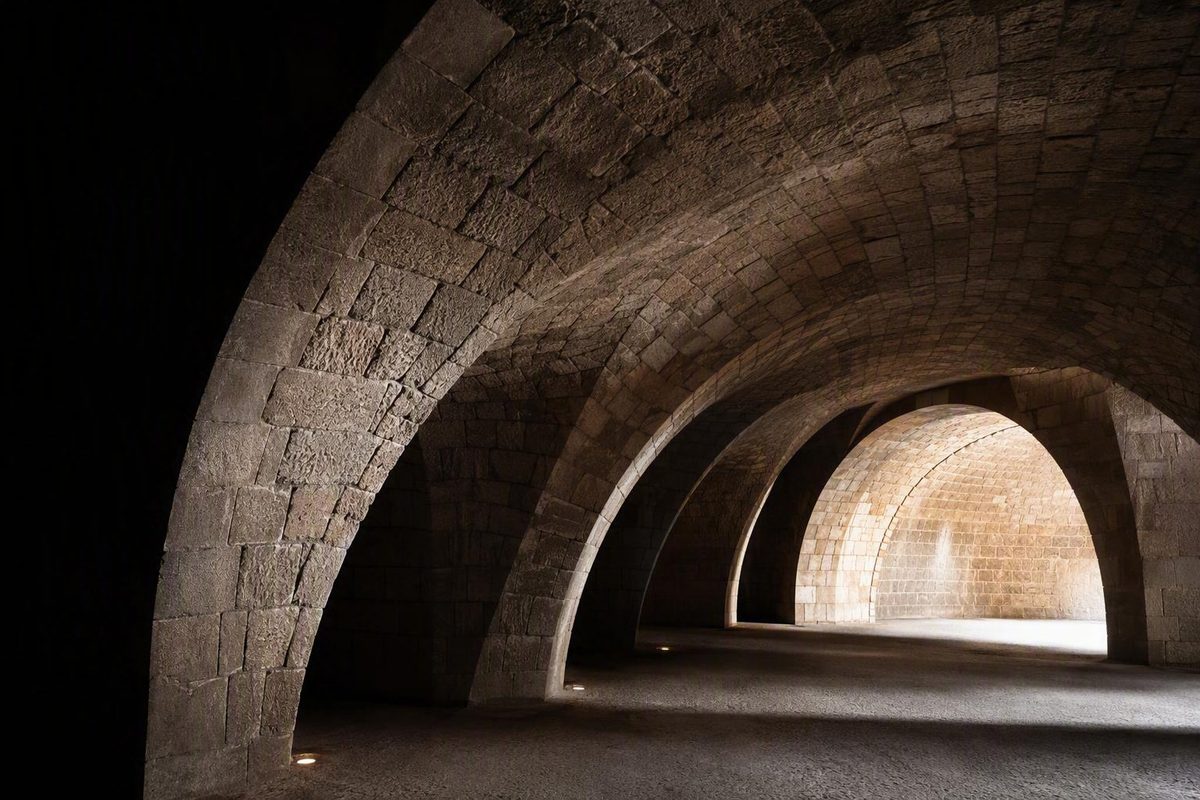
Stereotomic architecture organizes material as a substantial, compression-dominant mass. Gravity strongly influences the form, loads pass toward the ground through walls or curved surfaces, and rooms and openings often read as voids cut from or enclosed by solid material. The term does not simply mean architecture that looks heavy: classification depends on load paths, material continuity, joints, fabrication, and the relationship between solid and void.
What stereotomic architecture means
Two related meanings need to be separated.
Stereotomy traditionally means the geometric art or science of cutting solids, especially shaping stone into the blocks required for arches, vaults, domes, and other complex structures. Historical stereotomy coordinated projection, cutting, and assembly so that individually shaped pieces would form a stable whole. Matthias Rippmann and Philippe Block describe this development and its translation into computational fabrication in their paper on digital stereotomy.
Stereotomic architecture is the broader architectural idea. It treats a building, or a significant subsystem within it, as mass rather than as a visibly articulated framework. Structure is commonly organized around continuity, gravity, and compression, while space may be formed by cutting, hollowing, perforating, stacking, fitting, casting, or compacting. Subtractive design research similarly contrasts the removal of matter from a solid with tectonic construction based on assembling elements (Castellón González and D’Acunto).
Continuity does not mean the building must be one literal piece. A stone vault consists of separate blocks and joints, yet those units can act collectively as a compression-bearing mass. The useful question is whether forces pass through the body and contact surfaces of the construction—not whether the form was carved from one block.
The cave is a useful analogy because cave-like space appears hollowed from matter. But it remains an analogy. Darkness, visual weight, an earthbound character, or a rough finish may strengthen a stereotomic reading without proving how the building stands.
Short glossary
- Stereotomy: The geometric cutting of solids, especially stone blocks for complex construction.
- Stereotomic: Organized around substantial mass, continuity, compression, and often subtraction or perforation.
- Voussoir: A shaped masonry unit forming part of an arch, vault, or dome.
- Poché: The solid material shown between or around spaces, often filled or hatched in architectural drawings.
- Compression: A force that pushes or squeezes material together, as distinct from tension, which pulls it apart.
Stereotomic versus tectonic: compare how the building works
The most useful comparison is compression-bearing mass versus articulated assembly, not heavy versus light.
| Criterion | Stereotomic tendency | Tectonic tendency |
|---|---|---|
| Primary conception | Substantial mass or accumulated solid | Assembly of discrete members |
| Load path | Through walls, arches, domes, vaults, shells, or fitted units | Through posts, beams, frames, trusses, and connections |
| Typical elements | Walls, plinths, vaults, shells, voussoirs | Columns, beams, braces, panels, nodes |
| Joint expression | Joints may be visually absorbed while controlling contact and force transfer | Connections are usually distinct and may be expressed |
| Spatial operation | Space appears cut from, enclosed by, or perforated through mass | Space is defined between members and planes |
| Common analogy | Cave | Hut |
On the stereotomic side, gravity acts through accumulated material. A wall carries load through its thickness; an arch redirects forces along a curved path; a vault or dome distributes them across a surface and into supports. The tectonic side emphasizes differentiated members and the points where they meet—posts, beams, braces, plates, fasteners, knots, and joints.
“Cave versus hut” is therefore a useful memory aid but a poor specification. A cave-like concrete interior may conceal a conventional frame, while a thin stone vault may be strongly stereotomic. Structure, gravity, joints, and fabrication are more dependable criteria than apparent weight.
The distinction is also a spectrum rather than an absolute binary. A compression-dominant shell may need tension ties to contain its thrust. A framed building may include stereotomic foundations, retaining walls, cores, or podiums. Within a single wall, load-bearing backup and attached cladding may operate according to different structural logics.
Surface continuity should not be confused with structural continuity. Monolithic-looking concrete or masonry can conceal frame action, reinforcement, movement joints, anchors, or non-load-bearing veneers. The most accurate description may therefore apply to one subsystem or spatial operation rather than to the entire building.
A practical test: is a building genuinely stereotomic?
Use six checks before applying the term.
-
Material continuity Ask whether the construction acts as a substantial body. Separate masonry units can qualify when their geometry, bedding, and contacts create a coherent compression-bearing assembly. Stone panels attached to a frame do not become stereotomic merely because they form an uninterrupted surface.
-
Compression behavior Look for walls, arches, domes, vaults, or shells whose geometry channels a significant share of the load through compression. Record ties, reinforcement, anchors, and restraints where they exist rather than assuming a pure compression system.
-
Path of loads to the ground Trace gravity from the roof or vault through the supports to the foundations. Does it pass through broad areas of masonry or shell, or through discrete beams and columns? A deep opening matters structurally only in relation to the force path around it.
-
Role and expression of joints Determine whether joints govern contact, alignment, sliding resistance, tolerances, and assembly. A pattern scored into cladding is not equivalent to a bed joint or a shaped interface transferring force between voussoirs.
-
Making process Identify whether the work was cut, fitted, stacked, cast, compacted, or subtractively formed. Stone cutting is central to historical stereotomy, but broader stereotomic design can also involve accumulation, casting, or digital subtraction. The process should contribute to the organization of mass and construction rather than merely imitate a carved appearance.
-
Organization of solid and void Examine whether rooms, openings, courts, stairs, and skylights are treated as perforations within a materially substantial body. Academic design exercises have explored this reciprocal reading through stepped voids and solid extrusions, but such spatial studies do not by themselves establish a building’s structural system.
| Evidence level | What to look for | What it establishes |
|---|---|---|
| Strong evidence | Compression-oriented load paths and joint geometry that transfers force through mass | Supports a stereotomic classification |
| Supporting clue | Substantial walls, deep openings, continuous poché, carved or perforated space | Reinforces the reading but needs construction evidence |
| Not sufficient alone | Material name, visual heaviness, or a monolithic finish | Does not establish classification |
The fastest field test is to ask two questions together: Where does the load go, and what do the joints do? If neither can be answered, “stereotomic” is probably being used as a stylistic label.
Materials, forms, openings, and load paths
Stone and fitted masonry provide the clearest traditional examples because geometry, contact surfaces, cutting, and compression are directly connected. A shaped stone is not merely a finish unit: its faces can determine how it meets neighboring blocks, how it is positioned, and how forces pass through the assembly.
Brick, rammed earth, and concrete are also associated with broader interpretations of stereotomic design. They can produce mass through bonding and stacking, compaction, or casting, but the material name settles nothing by itself. Discussions of the stereotomic approach commonly include stone, brick, and concrete while emphasizing the manipulation or assembly of massive elements (Basilio Paredes Arquitectura y Diseño).
The recurring formal vocabulary includes:
- materially substantial walls;
- arches assembled from wedge-shaped voussoirs;
- barrel, groin, ribbed, or freeform vaults;
- domes and cupolas;
- plinths, podiums, and retaining masses;
- continuous shells or thickened surfaces.
In an idealized masonry arch or vault, curved geometry redirects gravity through compression toward the supports. The actual force path depends on geometry, loading, support conditions, joints, and thickness. Concentrated loads, support movement, earthquake loading, and construction-stage conditions can move a structure away from an ideal compression-only state. Temporary support may also govern behavior until an assembly is complete.
Openings complicate that force path. Doors, courts, windows, and skylights may be conceived as matter removed from an otherwise continuous mass, and their depth can make the subtraction visually legible. Yet every opening interrupts material and redirects force. A convincing spatial void still needs a workable load path around it.
Reinforced concrete requires particularly careful language. Cast continuity, thick surfaces, and deeply recessed openings can create a stereotomic spatial expression. If beams, columns, frame action, and tensile reinforcement govern the structure, however, describing the entire building as stereotomic may obscure its actual behavior. “Stereotomic concrete core” or “stereotomic spatial organization” may be more precise.
From traints and stonecutting to digital stereotomy
Historically, complex stone construction was laid out with orthographic projection drawings called traints. These drawings translated three-dimensional surfaces into the geometry needed to shape individual blocks or voussoirs. Designers had to coordinate the overall form, courses, joints, templates, cutting, and assembly before the completed vault could be seen.
A contemporary research workflow extends that chain:
- Define the architectural intent. Establish span, supports, circulation, openings, thickness goals, and the intended relationship between solid and void.
- Find a compression-oriented form. Develop a surface compatible with the intended loading and support conditions.
- Tessellate the surface. Divide the continuous geometry into courses, panels, or voussoirs.
- Generate blocks and contact faces. Resolve each unit’s interfaces, intrados, extrados, edges, and registration features.
- Test structure and fabrication. Evaluate stability, local thickness, contact forces, tool access, collisions, stock dimensions, handling, and assembly sequence.
- Fabricate the units. Convert validated geometry into machine instructions, templates, or cutting data.
- Assemble and survey. Position pieces using project-specific temporary works and measure actual deviations.
- Reassess the built geometry. Compare survey information with the design model as part of project-specific engineering before changes to temporary support or loading.
This is a conceptual workflow drawn from technical research, not a construction procedure or substitute for engineering. Thrust Network Analysis can inform vault geometry, local thickness, force direction, course organization, and contact-face orientation; subsequent structural assessment is still required. The same research associates planar faces with circular saws, singly curved faces with two-axis wire cutting, ruled surfaces with three- or four-axis wire systems, and more complex freeform geometry with multi-axis milling (Rippmann and Block).
| Fabrication method | Geometry generally favored | Main limitation |
|---|---|---|
| Circular saw | Planar faces | Restricted on continuously curved interfaces |
| Two-axis wire saw | Singly curved faces | Limited freedom of tool orientation |
| Three- or four-axis wire system | Ruled and some twisted surfaces | Requires clearance and feasibility checks |
| Multi-axis milling | More complex double-curved geometry | Greater machining complexity |
The cited four-axis experiment used CNC hot-wire cutting to make foam voussoirs that simulated diamond-wire stone cutting. It was not a direct, full-scale validation in natural stone.
A second digital branch begins with space rather than blocks. Programmatic rooms can be modeled as three-dimensional voids and subtracted from a bounding solid, leaving residual poché between them. In this approach, Boolean subtraction helps designers study spatial and structural parameters together during conceptual design.
The operation does not prove that the remaining solid has viable load paths, can be fabricated from the chosen material, accommodates services, or has a safe assembly sequence. Digital subtraction establishes a design model—not structural stereotomy by itself.
Worked case study: how the Armadillo Vault was designed and assembled
Project data: Armadillo Vault
- 399 individually cut limestone voussoirs
- Approximately 24 tonnes total
- Spans more than 15 metres in multiple directions
- Covers 75 square metres
- Maximum height of 4.3 metres
- Local thickness of 5 centimetres at midspan, increasing to 12 centimetres at touch-down and point-springing locations
- Individual blocks weighing approximately 45–135 kilograms
- Falsework offset inward and downward by 3 centimetres
- Reported machining tolerance of ±0.4 millimetres per voussoir
- Presented at the 2016 Venice Architecture Biennale
These project-specific figures come from the team’s technical account of the Armadillo Vault.
The Armadillo Vault is a documented contemporary application of traditional stereotomy, computational form-finding, structural analysis, and digital fabrication. Its limestone shell stands predominantly through compression without mortar or reinforcement between the blocks, while tension ties balance its thrusts. It should therefore not be described as a wholly compression-only system.
The team generated the funicular geometry through form-finding and optimization based on Thrust Network Analysis. Stone courses were oriented perpendicular to local force flow and divided into staggered voussoirs to promote interlocking; this course organization should be distinguished from the separate orientation of individual contact faces. Discrete-element analysis examined stability under concentrated loads, support settlement, and earthquake loading. Convex interfaces permitted circular-saw cutting, while disconnected extrados faces accommodated negative Gaussian curvature through a stepped exterior. Male-and-female registration grooves assisted positioning and helped resist local sliding. During test assembly, wooden shims positioned the blocks above scaffold-supported falsework, and the pieces were handled manually or with a lightweight jib crane. Keystone-row stones were cut after measurements of the partially assembled vault so the closure pieces could absorb accumulated deviation. All of these methods, including the reported tolerance, belong to this project rather than stereotomic construction generally (Armadillo Vault project paper).
Three lessons transfer more readily than the project’s dimensions or tolerances:
- Coordinate geometry with force flow. Overall form, course layout, contact faces, and support conditions should be developed together.
- Address fabrication and handling early. Tool access, face curvature, unit weight, lifting, registration, and temporary works can change the architecture.
- Plan for accumulated deviation. Surveying, adjustable positioning, closure pieces, and assembly sequence are design concerns rather than afterthoughts.
What the term does—and does not—tell a specifier or designer
“Stereotomic” is an analytical and design lens. It is not a substitute for structural calculations, code checks, material specifications, connection details, temporary-works engineering, tolerance schedules, or construction sequencing.
The concept is useful when it helps a team:
- read the relationship between mass and void;
- trace compressive load paths toward supports;
- coordinate surface geometry with courses and individual blocks;
- understand how joints transfer force and control assembly;
- reconcile openings with structural continuity;
- derive architectural expression from fabrication and construction.
Historical studies of cut-stone domes also show that construction geometry and ornament can be closely related. In examples associated with Andrés de Vandelvira and Philibert de l’Orme, concentric courses, projection methods, stone assembly, and moulding geometry are analyzed as connected systems. Those findings belong to the particular works examined, not to every building described as stereotomic (study of cut-stone vaults and domes).
The term alone says nothing reliable about comparative cost, embodied carbon, material waste, schedule, durability, seismic performance, or economic feasibility. Those outcomes depend on the material source, structural system, machinery, repetition, transport, labor, connections, temporary works, local requirements, and service-life assumptions.
A useful design-review prompt is:
Where does the load go, what holds tension, how are the units made and positioned, and are the voids compatible with the load path?
That question returns stereotomic architecture to its practical definition: the coordinated treatment of mass, void, gravity, compression, joints, and making—not visual heaviness alone.
Can a building combine stereotomic and tectonic construction?
Yes. A building may combine compression-bearing masonry walls or a substantial concrete core with a framed timber, steel, or concrete roof. A stone vault may also depend on tension ties, anchors, or temporary falsework. Classify each subsystem according to its load path, joints, and assembly rather than forcing the whole building into one category.
Does stereotomic architecture have to be made of stone?
No. Stone and fitted masonry provide the clearest historical examples, but brick, rammed earth, and concrete can support a stereotomic interpretation. The deciding factors are continuity, compression behavior, joint logic, making, and solid–void organization—not the material name alone.
Is every digitally carved or Boolean-modeled form stereotomic?
No. Subtractive modeling can create a stereotomic conception by treating rooms as voids within a solid. But a Boolean operation does not establish structural behavior, material continuity, machining access, connection design, constructability, or a workable construction sequence.
Are stereotomic structures always compression-only?
No. Compression may dominate the primary form, but real structures can require tension ties, reinforcement, anchors, or restraints. They must also accommodate loading and construction conditions that depart from an ideal compression-only model. Trace both the compressive load path and every element carrying tension before describing the system.