
Choose a Concrete Lintel by Loads, Bearing and Wall Detail
Learn how to choose a concrete lintel by system, loads, span and bearing, then coordinate reinforcement, installation, drainage and thermal details at openings.
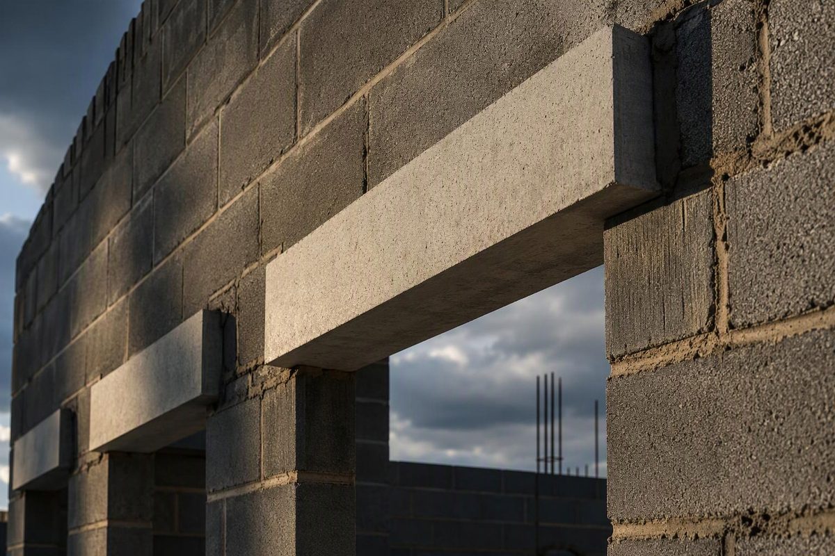
A concrete lintel is a reinforced or prestressed beam that carries masonry and any floor, roof or point loads over a wall opening. Choose it by structural system, load path, analysis span, bearing and serviceability—not by opening width alone—and coordinate it with the jambs and exterior-wall details.
Enter the clear opening and proposed end bearings to calculate the required overall length for coordination.
Overall Lintel Length Check
This calculates geometry only. It does not select a lintel or verify structural capacity.
Calculated overall length
1,200 + 102 + 102 = 1,404 mm
Verify both bearings and the lintel capacity for the project.
Source note: The equation and 102 mm sample bearings reflect the older CMHA TEK 17-02A coordination example described in the article. They are not a universal bearing requirement.
The length calculation does not establish capacity. A lintel of that length still requires verification for bending, shear, deflection, reinforcement development, bearing and every load delivered to the opening.
Choose the Lintel System Before Its Size
The term “concrete lintel” covers several systems. Matching width and length do not make them interchangeable.
| Lintel type | Useful where | Coordination that matters |
|---|---|---|
| Solid manufactured concrete masonry lintel | Repetitive CMU openings and available modular sizes | Product capacity, weight, orientation and bearing |
| Precast reinforced-concrete beam | Repetitive openings and factory-controlled production | Design basis, lifting, bearing and connections |
| Prestressed concrete lintel | Longer spans or shallower sections within a product range | Strand location, cutting limits, handling and temporary support |
| Precast U-lintel | CMU walls where the shell serves as permanent formwork | Field reinforcement, grout, development, shoring and composite capacity |
| Cast-in-place reinforced concrete | Nonstandard geometry, heavy loads or continuity with concrete construction | Formwork, bar congestion, cover, placement and curing |
| Reinforced CMU lintel or bond beam | Openings coordinated to block coursing | Lintel units, bottom bars, jamb reinforcement, grout and cleanouts |
The governing design basis depends on the product, not just its appearance. ASTM C1623 covers solid, reinforced, no-slump concrete masonry lintels and refers structural evaluation to TMS 402. It expressly excludes prestressed, U-shaped, grouted-CMU and slump-concrete lintels (ASTM C1623 scope). Other precast and cast-in-place concrete members may use the applicable structural-concrete provisions. Confirm the classification and design basis in the approved submittal.
For a closer comparison of factory-made forms, see precast lintel types and installation. For opening-head envelope issues, see window lintel detailing.
Size the Lintel From Its Loads
The clear opening establishes part of the span, but not the required capacity. Before selecting a lintel, record:
- wall thickness and the wythe or wythes requiring support;
- clear opening and proposed bearing at each end;
- masonry height above the opening;
- lintel self-weight and supported wall weight;
- roof, floor or balcony loads delivered to the wall;
- concentrated reactions from joists, beams, girders or posts;
- out-of-plane loads and required continuity for wind or seismic design;
- serviceability limits for masonry, glazing and finishes; and
- exposure, fire-resistance and thermal-envelope requirements.
CMHA separates lintel loading into lintel and wall dead load, distributed roof or floor load, concentrated reactions, and uniform load applied over only part of the span. Its reinforced-masonry guidance defines effective span as the center-to-center distance between supports, while its precast-concrete example uses the clear span plus member depth, limited by the distance between support centers. The applicable design method—not the rough opening alone—sets the analysis span (CMHA TEK 17-01D, CMHA TEK 17-02A).
Structural checks normally include positive bending, shear, reinforcement development or anchorage, bearing at each jamb and deflection. Reinforced concrete can develop additional long-term deflection from creep and shrinkage under sustained load. A lintel that passes a strength table can still be too flexible for brittle masonry, glazing or tightly fitted frames.
Arching Action Is Conditional
Masonry above an opening can sometimes form a compression arch and direct part of its weight around the lintel. Do not assume this merely because a 45-degree triangle can be drawn above the opening.
For the concrete-masonry condition it addresses, CMHA permits arching only with running-bond masonry, enough height to form a symmetrical 45-degree load triangle, at least 8 inches (203 mm) of masonry above the apex, adequate end bearing, no control joint adjacent to the lintel, and enough masonry beside the opening to resist horizontal thrust (CMHA TEK 17-01D).
A low parapet or adjacent control joint prevents use of that simplifying assumption. Loads applied within the triangle still must be included in the lintel design; CMHA notes that more than one method is used to distribute uniform loads within that area. If the required arching conditions are absent, account for the full wall weight and superimposed loads reaching the beam. Do not apply a stock-lintel table developed for a different load diagram.
Bearing Determines the Overall Length
The geometric relationship is: overall lintel length equals clear opening plus left bearing plus right bearing.
Older CMHA guidance for modular precast lintels used a minimum overall length 8 inches (203 mm) greater than the opening, providing 4 inches (102 mm) of bearing at each end. It also called for the lintel width—or the combined width of side-by-side members—to equal the supported masonry wythe (CMHA TEK 17-02A). Treat that as an illustrative coordination rule, not a universal current prescription. Required bearing depends on the adopted code, product approval, reaction, masonry strength and support condition.
Show bearing on the drawings rather than burying it in a product note. It affects the masonry opening, jamb-cell layout, frame clearance and purchasable lintel length. Distinguish among:
- Rough opening: the space required for the door or window assembly.
- Clear structural span: the distance between support faces.
- Effective span: the length used in structural analysis under the applicable method.
More bearing does not cure an understrength beam, and adequate beam strength does not cure a weak, hollow or poorly constructed jamb. High reactions may require grouted jamb cells, vertical reinforcement, a bearing element or another engineered means of distributing the load.
Drawings Must Define the Complete Lintel
A workable detail identifies more than an “8-inch concrete lintel.” Show or schedule:
- exact lintel type and product designation, or cast-in-place section;
- actual width, depth and overall length;
- clear opening and bearing at both ends;
- design strength and reinforcement or prestressing designation;
- required top orientation and lifting points;
- field reinforcement and grout for a U-lintel, including development and splices;
- temporary shoring and the condition for its removal;
- supported wythes and any separate veneer support;
- flashing, end treatment, weeps, drip and sealant transitions;
- insulation and air-barrier continuity; and
- restrictions on cutting, drilling, chasing or anchoring.
Coordinate this information across structural elevations, wall sections, opening schedules and specifications. Align the depth with CMU dimensions and coursing, particularly where the head must land on a bed joint.
Installation Details Can Change Capacity
Set the member at the designed elevation on sound, level supports with full specified bearing. Keep the marked top upward because reinforcement is often asymmetric. CMHA recommends marking precast lintels to prevent upside-down installation and notes that storage, transport and placement can produce tensile stresses unlike those in the completed wall (CMHA TEK 17-02A).
Follow the selected product’s instructions for lifting, cutting, drilling and propping. Requirements vary. Naylor, for example, requires its lintels to bear on a level full mortar bed and calls for temporary propping on spans over 1,200 mm in its product range. It prohibits rebates and chemical-anchor holes while permitting limited plugging, drilling and cutting under stated conditions that protect the prestressing tendons (Naylor installation guidance). Those manufacturer-specific instructions illustrate why a generic note cannot replace an approved submittal.
Do not shorten, notch or drill a reinforced or prestressed lintel unless the applicable product instructions or project engineer permit the exact operation. An unapproved cut can reduce bearing, sever reinforcement or strand, remove anchorage length and invalidate the listed capacity.
Complete the Wall Above the Lintel
The lintel is only one part of the opening. In an exterior wall, continue the assembly’s water, air and thermal control layers across the head. Where the wall is designed to drain, provide the specified flashing, weeps and drip. Detail the flashing ends to keep collected water from running into the jambs, and keep drainage paths clear of mortar droppings.
CMHA identifies openings as locations requiring specific moisture detailing and describes surface protection, internal protection, and drainage or drying as complementary defenses. It also cautions that flashing details can affect structural continuity in reinforced masonry, so the architecture and structure must be coordinated rather than detailed independently (CMHA TEK 19-02B).
Check the thermal bridge as well. A full-depth concrete lintel can bypass insulation at the opening head. Possible responses include separate support for different wythes, insulation routed around the structural member, or a tested thermally improved system. The selected detail must still preserve bearing, fire performance, drainage and the required load path.