
How to Choose and Detail a Concrete Lintel Over a Masonry Opening
Screen options by wall construction, clear opening, bearing, supported width, loads and form—not stock length alone.
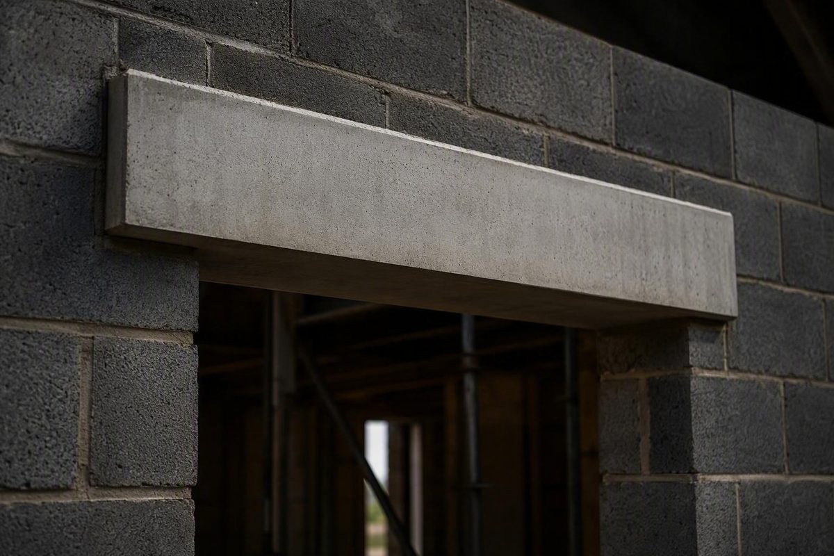
A precast concrete lintel is a factory-made structural beam that bridges a masonry opening and transfers the supported wall and other loads to the masonry at each end. Preliminary selection starts with the wall construction, clear opening, available bearing, supported wall or wythe width, loads above, and required lintel form. A matching stock length is not enough: the exact unit must also satisfy bearing, flexure, shear, deflection, reinforcement, handling, and installation requirements.
This guide covers preliminary selection and detailing checks, not a construction-ready structural or envelope detail. Final dimensions, reinforcement, bearings, flashing, temporary support, and installation requirements must come from current product documents, project drawings, applicable codes, and the responsible design professionals.
The short answer: what a precast lintel does and how to screen one
A lintel creates a load path around a door, window, service opening, or other interruption in masonry. Loads pass through the member to its end bearings and then into the jamb masonry. Selecting one therefore involves more than measuring the opening: the lintel, its supports, and the construction above it must work as a coordinated system.
Begin preliminary screening with six inputs:
- Wall construction: Identify the masonry material, bond, thickness, number of wythes, cavity arrangement, and whether each wall portion is structural, veneer, or part of a combined system.
- Clear opening: Measure the distance between supporting jamb faces rather than relying on a door, window, or nominal rough-opening label.
- Available bearing: Measure usable support at both ends and note corners, control joints, vertical reinforcement, embedded items, recesses, and other interruptions.
- Supported width: Establish which wythe or portion of the wall bears on the lintel. Multi-wythe construction may need separate members or a project-specific assembly.
- Loads above: Identify masonry self-weight, floors, roofs, joists, trusses, intersecting walls, equipment, and concentrated reactions.
- Required form: Determine whether the detail calls for a solid member, U-shaped unit, composite lintel, prestressed product, AAC-system lintel, or another system-specific form.
These inputs narrow the available choices; they do not complete structural selection. A unit with the desired nominal section and overall length may still be unsuitable because its reinforcement, concrete properties, bearing assumptions, supported load pattern, construction configuration, or deflection performance differs from the project requirements.
Depending on the product and application, design review may need to address flexure, shear, bearing at the lintel and supporting masonry, immediate deflection, long-term deflection, reinforcement development, and stresses during storage, transport, lifting, or placement. CMHA guidance also recommends top and bottom reinforcement where temporary tensile stresses may occur during handling and placement, illustrating why final-service loading is not the only consideration in lintel design (CMHA technical guidance).
Final selection should use the current original load and deflection tables for the exact product, the locally adopted codes and amendments, the structural drawings, and qualified professional review where required.
Solid, U-shaped, composite, prestressed, and AAC lintels compared
The appropriate lintel form depends on how the member is intended to resist loads and what work must be completed on site.
| Type | How it works | Essential field check |
|---|---|---|
| Solid reinforced | Complete beam with embedded reinforcement | Orientation, bearing and exact capacity |
| U-shaped | Channel completed only as specified | Whether fill, bars and support are required |
| Composite U-lintel | Unit, grout, bars and masonry act together | Complete designed depth, bond and curing |
| Prestressed | Strand introduces compression | Handling, orientation and alteration restrictions |
| Reinforced AAC | Member for a specific AAC wall system | System compatibility and its own load table |
A solid reinforced lintel arrives as a complete member. Its concrete section and embedded reinforcement resist the actions assigned to it without field-filling a channel. Two products with the same nominal dimensions are not necessarily equivalent: reinforcement size and position, concrete properties, cover, overall length, and design assumptions can differ.
A U-lintel has a longitudinal channel. Depending on the engineered detail, it may remain unfilled or receive field reinforcement and grout. If the U-unit, reinforcement, grout, and masonry are designed to act together, the completed assembly may function as a composite lintel or continue as a reinforced bond beam.
Published dimensions help identify product formats, but they do not establish capacity. York, for example, lists solid sections of 4 by 8, 6 by 8, and 8 by 8 inches, and U-shaped sections of 6 by 8, 8 by 8, 10 by 8, and 12 by 8 inches. The manufacturer states that the lintel types have distinct loading properties, so even products within one range should not be treated as structurally interchangeable (York product information).
A prestressed lintel uses prestressing strand rather than relying only on conventional reinforcing bars. It may serve different span or load ranges, but its orientation, permissible supports, capacity, handling requirements, and alteration restrictions belong to the individual product. Permission to modify a conventionally reinforced U-lintel from one series does not establish permission to modify a prestressed unit.
AAC lintels are specialized reinforced members for their designated autoclaved aerated concrete wall system. Do not transfer their load tables to ordinary concrete products.
Opening size, bearing, overall length, and wall width
Keep the coordination dimensions distinct:
ELEVATION — SIMPLE CASE

        <----------- overall lintel length ----------->
        ┌─────────────────────────────────────────────┐
        │               precast lintel                │  ↑
        └─────────────────────────────────────────────┘  │ lintel
        <--- bearing --->               <--- bearing --->│ depth
     ████████████████                     ████████████████↓
     █  jamb masonry █                   █ jamb masonry  █
     █                █<-- clear opening ->█              █
                      <--- design clear --->
                            span*

*In this simple sketch, the clear opening and design clear span coincide.
 Recesses, support geometry, or the applicable design method may make the
 effective design span different from the measured opening.

TYPICAL U-LINTEL SECTION

        <------ supported wythe / lintel width ------->
        ┌─────────────────────────────────────────────┐
        │   ┌──────────── U-channel ─────────────┐    │
        │   │               grout                │    │
        │   │          ● reinforcement           │    │
        │   └────────────────────────────────────┘    │
        └─────────────────────────────────────────────┘
For preliminary coordination:
Physical overall lintel length = measured clear opening + physical bearing at the first end + physical bearing at the second end
The effective span used in structural calculations may differ from the clear opening. Do not substitute it into this physical-length sum: that can count part of the support distance twice.
Suppose project-specific documents require 4 inches of bearing at each end of a 48-inch opening:
48 in. + 4 in. + 4 in. = 56 in. preliminary overall length
That calculation identifies only a candidate length. It does not verify bearing stress, supporting-masonry strength, flexure, shear, reinforcement, or deflection. The 4-inch-per-end value comes from US association guidance for the modular precast lintels addressed there; it is not a universal minimum. That guidance also says the lintel width, or combined width of side-by-side lintels, should equal the supported masonry wythe.
Required bearing varies with the exact product, supporting masonry and project design.
Width requires the same care. An 8-inch wall does not establish that any nominally 8-inch lintel is suitable. Determine whether the member supports the entire wall, one wythe, an inner structural leaf, or another defined portion. Where more than one unit is proposed, verify the support and load distribution using the project-specific design rather than simply adding catalog capacities.
Keep these four specifications separate:
- Nominal section: The product’s named width and depth.
- Available overall length: The length in which the unit is manufactured or supplied.
- Allowable opening or clear span: The span permitted under stated support and loading assumptions.
- Rated capacity: The verified resistance for the exact section, reinforcement, materials, span, and construction configuration.
A cataloged overall length does not establish that the unit can bridge a particular opening under the project’s loads.
Structural selection: loads, strength, deflection, and masonry arching
Once a candidate form and size have been identified, work through the structural questions in sequence:
- Establish the design loads. Include lintel self-weight, masonry above, supported floor or roof loading, and concentrated reactions where present.
- Define the clear span and supports. Confirm the effective span, restraint assumptions, jamb construction, and nearby discontinuities.
- Verify bearing. Check the required bearing length and the bearing stresses in both the lintel and supporting masonry.
- Check flexure and shear. Compare the required actions with the verified resistance of the exact product or engineered assembly.
- Check service-load deflection. Evaluate movement under expected service loading, not only resistance under factored loads.
- Account for long-term effects. Sustained loading, creep, and shrinkage can increase deflection over time.
- Confirm the complete configuration. Match the section, reinforcement, concrete properties, orientation, grout, composite height, masonry bond, and temporary-support assumptions to the applicable design information.
Strength and serviceability are separate. Published guidance uses different deflection criteria for different supported construction and assumptions. The applicable limit must therefore come from current governing documents rather than a generic ratio.
Masonry arching is also a conditional engineering model, not automatic additional capacity. A 2021 York-identified design guide hosted on Tidewater Block’s domain allows arching to be considered only under stated conditions, including running-bond masonry, a completed and fully cured wall, adequate bearing, sufficient masonry beside and above the opening, and no nearby control joints or similar discontinuities. When the model applies, the lintel may still carry its own weight, masonry within the triangular zone, and concentrated loads within that zone (2021 lintel design and installation guide).
Do not assume arching where an opening is close to a corner, the wall above is too low, the masonry is stack-bonded, the wall is incomplete, a joint interrupts the load path, or a concentrated reaction falls unfavorably. Whether arching applies belongs in the structural analysis.
Never transfer a load table between manufacturers or product families. A table applies only to its identified geometry, reinforcement schedule, concrete properties, support assumptions, load pattern, and composite configuration. Similar appearance or nominal dimensions do not establish equivalent performance.
Pre-installation and site inspection checklist
Installation must preserve the configuration used for selection and design. Requirements for lifting, curing, temporary stability and prop removal must come from current instructions for the exact unit and the approved project documents.
Before and during placement, verify:
- Delivery condition: Apply the project’s acceptance criteria to cracks, spalls, exposed reinforcement, damaged bearing ends, distortion, or other transport damage. Do not install a questionable unit until its disposition has been approved.
- Product identity: Match markings, section, length, product series, and reinforcement or prestressing designation to the approved submittal.
- Orientation: Identify the marked top, rough face, notches, or other directional features and install the member as required. CMHA guidance recommends marking the top to reduce the risk of upside-down installation.
- Bearing and supports: Confirm the specified bearing at both ends after allowing for construction tolerances. Verify that the jamb masonry and support surfaces conform to the structural drawings.
- Bedding: Use the mortar bed, pad, or other support treatment required by the current product instructions and project detail.
- Lifting: Follow the approved lifting procedure for the exact unit, including any specified lifting locations, equipment requirements, handling restrictions, and temporary-stability measures.
- Temporary support: Install and retain shoring or props only as required by the current product documents and project design. Remove them only under the specified release conditions.
- Reinforcement: For a composite U-lintel, verify bar size, quantity, lap or development requirements, cover, and exact position before grouting.
- Grout: Use the specified material and follow the approved placement, consolidation, curing, and inspection requirements.
- Masonry bond: Construct the bond pattern and composite height assumed in the design.
- Exterior protection: Coordinate the specified coating, flashing, cavity drainage, weeps, insulation, and exposure details.
- Drawing conformity: Resolve conflicts among architectural, structural, shop, and manufacturer documents before work proceeds.
Orientation markings matter because reinforcement and prestressing configurations are product-specific. Installing a member contrary to its required orientation can produce a configuration different from the one used for design. Reinforcement may also be required for temporary tensile stresses during storage, transportation, handling, or placement, not just for final service.
For composite U-lintels, field-added reinforcement must occupy the detailed position, and the grout and masonry must meet the specified system requirements. Cast-Crete’s 2015 catalog, for example, places field-added bottom reinforcement at the bottom of the U-lintel cavity and calls for running-bond composite masonry, shoring as required, and an approved coating on exposed exterior U-lintel surfaces. Those provisions apply to the identified product system and should not be converted into universal specifications (Cast-Crete technical catalog).
Do not assume that cutting, drilling, chasing, or notching is acceptable. Cast-Crete’s 2015 catalog permits field cutting of certain U-lintels, but that product-specific permission does not apply automatically to another reinforced or prestressed unit. Any proposed alteration requires written approval covering the exact product and modification. Grout placement, curing, lifting, temporary support, stability, and prop removal must likewise follow current product instructions and approved project documents.
Procurement checks: why an available lintel may still be the wrong lintel
An order or submittal must identify the structural product, not merely a concrete unit with the desired dimensions.
Record:
- Manufacturer and product series
- Lintel type: solid, U-shaped, composite, prestressed, or system-specific
- Nominal and actual section
- Overall length
- Supported wall or wythe width
- Reinforcement or prestressing configuration
- Specified concrete strength
- Unit weight
- Required orientation
- Required bearing
- Applicable load-and-deflection table reference
- Fire-resistance requirement
- Finish, coating, and exposure requirement
- Delivery, access, lifting, and storage constraints
- Submittal and approval status
Retail listings show why this distinction matters. Extech’s category page lists concrete lintels in 4-by-8-inch and 6-by-8-inch sections and in multiple lengths between 32 and 144 inches. The page provides no reinforcement, concrete strength, capacity, bearing, certification, unit weight, or installation information, so it cannot support structural selection (Extech retailer listing).
Fire performance requires similar care. York publishes different stated fire ratings for different lintel sizes and types, confirming that a “concrete lintel” is not a single fire-performance category.
Document freshness matters. The cited Cast-Crete catalog is dated 2015, and the York-identified design guide is dated 2021. These documents are useful examples of how product systems have been specified, but they may not reflect current products, capacities, codes, warranties, or availability. Obtain current primary manufacturer documents and original load and deflection tables for the exact unit rather than relying on historical examples, extracted tables, retailer descriptions, or another brand’s literature.
Require explicit review by the responsible structural professional for long spans, point loads, limited bearing, openings near corners or control joints, unusual geometry, multi-wythe construction, proposed structural alterations, uncertain supporting masonry, or any condition outside a current product table.