
Load-Bearing Wall Diagrams: From Floor Framing to Foundation
Read load-bearing wall diagrams in section and elevation, trace loads around openings, and calculate a simple tributary-width example.
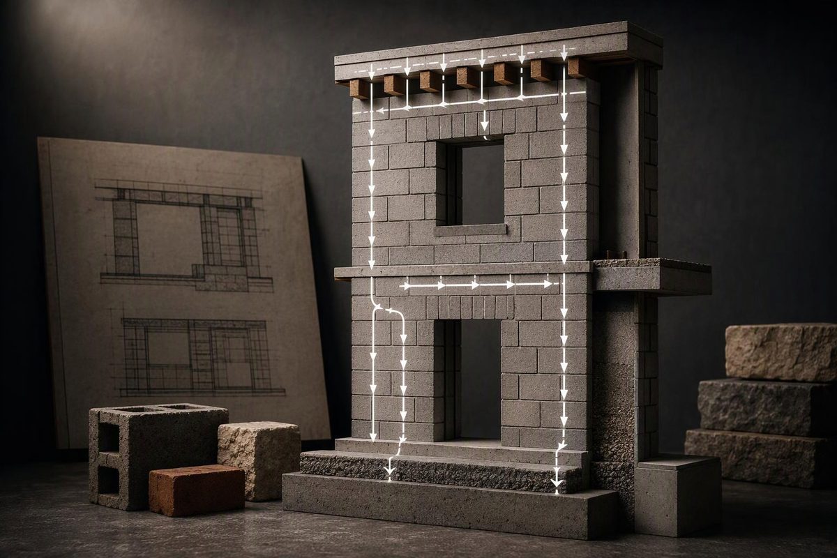
A load-bearing wall diagram should show what bears on the wall, how the load travels through it, and what supports it below. A thick line on a floor plan cannot explain all three.
The schematics below illustrate gravity-load paths in timber construction. They are not framing specifications or permission to remove a wall. Arrows show downward load transfer; member sizes, fasteners and bearing lengths require project-specific design. Neither diagram is to scale.
1. Section: follow the load down
A section cuts vertically through the building. This simplified example shows two separate, simply supported floor spans meeting at an interior bearing wall—not continuous joists spanning across it.
SECTION — FLOOR SUPPORTED ON THREE WALL LINES

        Floor weight + imposed loads
        ↓ ↓ ↓ ↓ ↓ ↓ ↓   ↓ ↓ ↓ ↓ ↓ ↓ ↓
        ┌─────────────┐ ┌─────────────┐
        │ Left span   │ │ Right span  │ Floor framing
        └─────────────┘ └─────────────┘
        ↓              ↓              ↓
     Exterior       Interior       Exterior
     bearing        bearing        bearing
     wall           wall           wall
        │              │              │
        ↓              ↓              ↓
     Foundation     Foundation     Foundation
        ↓              ↓              ↓
     ───────────── Supporting soil ─────────────
The important feature is the support at each end of each span. The interior wall receives reactions from both floor spans. Those reactions pass through the wall and its support below to the ground.
In a timber wall, the load passes through the plates and studs. At floor levels, the intervening framing must transfer that load to the next support. If an upper bearing wall is offset from the wall below, the diagram needs to show the beam, slab or other structural assembly that bridges the offset—not simply continue an arrow through empty space.
The U.S. Department of Energy’s Building America guidance on continuous load paths explains that loads must reach the ground through connected structural elements. It also identifies connections between roof, wall, floor and foundation assemblies as potential weak links.
A non-load-bearing partition, by contrast, does not intentionally support the floor or roof above. Its own weight still needs support. For that distinction, see load-bearing versus non-load-bearing walls.
2. Elevation: route loads around an opening
An elevation looks along the face of the wall. It reveals a load-path interruption that the section above does not: a door, window or passageway.
WALL ELEVATION — LOAD PATH AT AN OPENING

             Loads from above
             ↓   ↓   ↓   ↓
          ┌───────────────────┐
          │   HEADER / BEAM   │
          └───────────────────┘
          ↓                   ↓
     End support         End support
     (post or            (post or
      jack studs)         jack studs)
          │                   │
          │   CLEAR OPENING   │
          │                   │
          ↓                   ↓
       Verified            Verified
       support below       support below
The header collects load above the opening and transfers it to the end supports. The American Wood Council’s header guidance describes this redistribution to adjacent studs and identifies opening width and supported weight as key sizing considerations.
This changes the drawing in two ways:
- The header needs a defined span and bearing detail. Clear opening width, total member length and the span used in calculations are not interchangeable.
- The end reactions need a route downward. A beam spanning a removed wall can concentrate loads at its posts. The floor, beam, foundation or other assembly beneath each post must be checked for that reaction.
Timber design checks extend beyond beam bending: they include shear, deflection, compression, bearing and connections, as demonstrated in WoodWorks’ gravity-framing design guidance.
In a masonry wall, the horizontal member is generally called a lintel. Do not automatically draw all masonry above it as a simple rectangular load: arching can redistribute loads, but only under suitable conditions. CMHA’s concrete masonry lintel guidance explains that distinction. Its tables are based on the 2012 IBC and 2011 MSJC, not necessarily the project’s applicable design standard; see also concrete lintel sizing and detailing.
3. Put numbers beside the arrows
Tributary width is the width of floor whose load is assigned to a support. For uniformly loaded, simply supported, one-way floor spans of 12 ft and 16 ft meeting at an interior wall:
- Contribution from the left span: 12 ÷ 2 = 6 ft.
- Contribution from the right span: 16 ÷ 2 = 8 ft.
- Total tributary width: 6 + 8 = 14 ft.
Assume an illustrative total floor load of 50 lb/ft², not a specified code load. The equivalent line load on the wall is:
w = 50 lb/ft² × 14 ft = 700 lb/ft
If a simply supported replacement beam carries that uniform load over an 8 ft support-to-support span, each end reaction is:
R = wL ÷ 2 = 700 × 8 ÷ 2 = 2,800 lb
Here, closely spaced joist reactions are idealized as a uniform load. Actual reaction locations and any additional concentrated loads must be considered in the project analysis.
This calculation illustrates redistribution, not beam selection. It excludes beam self-weight, walls or roofs above, and additional concentrated loads. Continuous spans, cantilevers and unequal loading require a different analysis. WoodWorks’ worked examples show the conversion from area load to line load and the corresponding simply supported beam relationships.
What the project drawing must add
Before a conceptual diagram becomes a construction detail, identify:
- Framing direction, spans, actual bearing points and loads from above.
- Member material, grade or product designation, dimensions and connections.
- Opening width, bearing lengths, end reactions and support below.
- Any offset between supports at successive levels.
- Lateral bracing, uplift restraint and other structural roles affected by the opening.
A downward-arrow diagram shows only gravity behavior. The same wall may also resist wind or earthquake loads. Before cutting or removal, have its roles and the permanent and temporary support arrangements verified by a qualified structural professional, and check local approval requirements. The UK Health and Safety Executive’s structural-stability guidance calls for assessment before altering potentially load-bearing parts and for designed temporary supports capable of withstanding foreseeable loads; its regulatory advice applies in Great Britain.
For existing buildings, start with tracing loads above and below a possible bearing wall.