
Trace the Load Path Before You Remove a Wall
Follow joists, roof framing and support below to assess whether a wall is load bearing, then learn which clues cannot safely authorize removal.
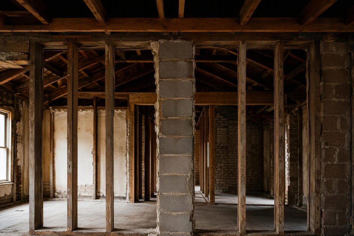
To tell whether a wall is load bearing, trace what rests on it and where that load goes below it. A bearing wall transfers gravity loads from a roof, floor, beam or wall above toward a footing or foundation. Its location, thickness and direction relative to the joists are useful clues, but no single visual clue proves the answer.
If the wall will be cut, opened or removed, identifying it is only the first step. The replacement beam, end posts, connections, support below and temporary shoring must also be resolved.
Select the conditions you can verify; the result shows how to treat the wall.
Wall Evidence Check
Choose only what you can confirm from drawings or exposed framing.
Trace the framing above and support below before cutting or removing the wall.
Source basis: HUD Residential Structural Design Guide and American Wood Council I-joist guidance. This check is not a structural design or removal approval.
Start With the Load Path
Think in section rather than plan:
roof or floor framing → wall or beam → wall, beam or posts below → footing or foundation
HUD’s Residential Structural Design Guide treats a house as a structural system and illustrates separate vertical and lateral load paths through its floors, walls, roof and connections (HUD). A useful investigation therefore covers at least one level above and one below the wall. Looking only at the room containing the wall leaves much of the evidence hidden.
Check the Drawings First
Look for:
- structural and architectural floor plans;
- floor- and roof-framing plans;
- beam, header and footing schedules;
- sections through the wall;
- truss placement plans and individual truss design drawings;
- records of additions and earlier alterations.
A structural plan may label bearing walls or show joist ends, beams and truss bearing points. An architectural plan alone may not record every structural condition.
For an engineered truss roof, use the project’s truss documents rather than relying on a rule about ridge direction. The Structural Building Components Association’s guidance treats dimensions, loads, girders, deflection, bearings and bracing as specific information on the truss design drawings (SBCA).
Inspect the Framing Above the Wall
Use an accessible basement, crawlspace or attic where possible. If finishes must be opened, choose the location deliberately and first account for wiring, plumbing, ductwork and hazardous materials that may be present in older construction.
Joists Ending or Lapping Over the Wall
A wall is likely bearing when floor or ceiling joists run perpendicular to it and:
- terminate on its top plate;
- overlap or splice above it;
- change direction at it; or
- connect to a beam that bears on posts within the wall.
The mechanism is direct: the joist reactions enter the wall as a line load and continue downward. The American Wood Council notes that I-joists require end support at beams or bearing walls and may need intermediate supports depending on span. Its guide also identifies load-path continuity from roof and floor framing to the footings as a central structural principle (AWC).
Joists Running Parallel to the Wall
Parallel framing makes a wall less likely to support that floor, but it does not establish that the wall is nonbearing. The wall could support:
- a concealed beam within the floor depth;
- a doubled joist or framing around an opening;
- a bearing wall or post from the story above;
- a roof purlin, structural ridge support or girder truss;
- a concentrated load landing at one point.
Engineered floor systems make casual assumptions particularly risky. For example, Weyerhaeuser’s October 2025 wall guide for California, Nevada and Arizona says that, within its conventional-construction applications, load-bearing walls over TJI joists must stack directly over bearing walls or beams below (Weyerhaeuser). The project-specific joist layout and product literature govern.
Inspect Below the Wall
Support below is often the strongest visible clue. Check whether the wall aligns with:
- a foundation wall;
- a beam or girder;
- a row of columns or posts;
- another wall on the story below;
- a thickened slab or continuous footing shown on the drawings.
Confirm alignment by measurement, not by sighting from different rooms. Use a common reference such as an exterior wall, stair opening or plumbing stack.
A designed beam can shift the load path sideways, so perfect vertical stacking is not universal. Conversely, a partition may happen to align with a basement beam without bearing on it. Alignment is evidence, not proof.
The City of Los Angeles’ prescriptive provisions for qualifying one-story wood-frame residential construction illustrate the relationship: exterior walls, interior bearing walls and braced wall panels require continuous footings in that system (Los Angeles Department of Building and Safety). Other buildings may use designed beams, transfer members or different foundation systems, so the absence of an obvious footing does not clear a wall for removal.
Read the Roof Separately
At the top story, identify the actual roof system.
- Conventional rafters: Exterior walls commonly receive the lower rafter reactions. Interior walls or posts may support structural ridges, purlin braces, ceiling joists or intermediate rafter supports.
- Prefabricated trusses: Many span between exterior bearings, but some have interior bearing points. Girder trusses can also deliver concentrated reactions to internal walls or posts.
- Low-slope roofs: Joists, beams and girders may not follow the direction suggested by the visible roof surface.
Do not infer bearing from the roof ridge alone. Hips, valleys, dormers, openings and additions can redirect loads locally.
Use Visible Details Only as Clues
| Visible clue | What it may indicate | Why it is not proof |
|---|---|---|
| Wall perpendicular to joists | Possible joist-bearing line | Joists may span across it without bearing |
| Wall directly over a beam or wall | Possible continuous load path | Alignment may be coincidental |
| Built-up member over an opening | Loads may transfer around the opening | Nonbearing partitions also use substantial framing |
| Doubled studs or posts | Possible concentrated reaction | Extra studs may support fixtures or finish transitions |
| Double top plate | Conventional framed-wall construction | Bearing and nonbearing walls may both have double plates |
| Masonry or concrete | Potential structural wall | It may be veneer, infill or a nonbearing partition |
| Exterior location | Possible floor, roof or lateral support | Curtain walls and some gable-end walls carry little gravity load |
A substantial header is a reason to investigate, not permission to remove the studs around it. A structural opening needs adequate end bearing and a continuous path below—the same coordination required when detailing a window lintel.
“Non-Load-Bearing” Does Not Mean Removable
A wall that carries little or no gravity load may still brace the building against wind or earthquake forces, form part of a fire-resistance assembly, protect an exit route or restrain framing.
FEMA identifies the building envelope, openings and load-path connections as separate areas that must work together for wind resistance (FEMA). UK building-control guidance similarly notes that some internal walls protect stairs and escape routes even when they are not gravity-bearing (Building Control Partnership). Finish and framing material are also unreliable indicators: both wood and metal studs can form structural or nonstructural assemblies.
Before Cutting or Removing the Wall
If drawings and inspection do not establish a complete load path with confidence, do not start demolition. Have a qualified design professional assess it, particularly in masonry buildings, balloon framing, post-and-beam construction, engineered joist or truss systems, mixed-age additions and buildings with offset loads.
A new opening or wall removal must resolve more than beam depth:
- loads from every supported level;
- beam span, material, strength and deflection;
- bearing length and posts at both ends;
- connections and lateral restraint;
- capacity of the floor, beam or footing below each post;
- temporary support and construction sequence;
- fire protection and concealed services.
Permit requirements are local. Seattle, for example, requires a permit for work on load-bearing supports regardless of project size (Seattle Department of Construction and Inspections). Oregon lists adding, moving or removing walls among residential alterations requiring a building permit (Oregon Building Codes Division). Check with the authority having jurisdiction before demolition.
The practical test is not whether the wall looks structural. It is: Can every gravity or lateral load entering this wall be traced through known members and connections to adequate support? If that chain cannot be demonstrated, the wall has not been cleared for alteration.