
Trace the Load Path Before You Cut a Wall
Learn to trace loads above, below and along a wall, read framing clues, check other structural roles and know when professional verification is required.
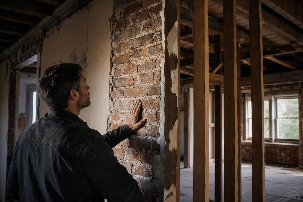
The reliable way to find out if a wall is load bearing is to trace what rests on it and where that load goes below. Tapping the drywall, measuring wall thickness or checking joist direction alone cannot establish the answer. If you plan to cut, widen or remove the wall, keep it intact until its load path and other structural roles have been professionally verified.
The 2021 International Residential Code defines a load-bearing wall as one supporting any vertical load in addition to its own weight. A nonbearing wall supports no vertical load other than its own weight (ICC, Chapter 2 definitions). The practical question is whether the wall receives load from a floor, roof, wall, beam, post or other structural element and transfers that load toward the foundation.
Select what you can observe above, below and around the wall; the result shows how to treat it before alteration.
Screening Result
Undetermined — do not cut the wall.
The default selections contain no visible evidence. Inspect above, below and along the wall, then obtain qualified verification before alteration.
A confirmed bearing point carries more weight than framing direction alone.
A hidden or reinforced support may exist even when none is visible.
“None identified” is not proof that no such role exists.
Basis: 2021 IRC load-bearing definitions and the load-path inspection clues summarized in this article. This is a screening result, not a structural design or site verification.
Start With the Drawings, Then Verify the Building
Look for original structural drawings, permit drawings and records of later alterations. Useful sheets include:
- foundation and floor-framing plans;
- roof-framing or truss-placement plans;
- building sections;
- beam, header and column schedules;
- notes identifying bearing, shear or braced walls.
Architectural floor plans alone may not show the structural system. Records are not proof of existing conditions either: framing can differ from the approved design, and later renovations may be undocumented.
Records may also be unavailable. Los Angeles County, for example, says it typically discards single-family residential plans 90 days after completion and suggests contacting the original builder, designer or engineer using information from the permit (LA County Building and Safety). This policy applies to that county and does not establish how long another authority retains plans.
Use drawings as a map, then compare them with what is visible in the basement, crawlspace, attic or accessible ceiling cavities.
Trace the Wall in Three Directions
Assess the whole vertical section of the building rather than only the room containing the wall.
Look Above for Loads Ending at the Wall
A wall is more likely to be bearing when it supports:
- the ends of floor joists;
- a lap or splice between joists;
- a beam or girder;
- another wall on the story above;
- roof rafters, ceiling joists, purlin struts or a designated truss bearing line;
- a concentrated load from a post, chimney support or transfer beam.
The UK Planning Portal identifies roofs, walls above and floor joists as common elements carried by internal load-bearing walls. It also describes less obvious arrangements, such as an internal wall supporting a beam beneath a retained chimney stack (Planning Portal).
Joists running perpendicular to a wall are only a preliminary clue. Determine whether they end, overlap or are otherwise supported there. Joists can also span continuously across a partition without relying on it.
Look Below for a Continuous Support
Find what supports the wall or the concentrated loads within it. Possible supports include:
- a foundation wall or continuous footing;
- a basement beam or girder;
- a row of posts;
- a thickened slab or grade beam shown on structural drawings;
- another wall continuing to the foundation.
A wall directly over a beam or foundation is a strong clue, but the absence of an obvious support does not settle the question. It may bear on reinforced floor framing, or the support may be concealed. Conversely, a partition can align with a beam without carrying load.
Follow the path through every level. A wall supported by floor joists is not necessarily nonbearing; those joists may have been designed to transfer its load elsewhere.
Look Along the Wall for Concentrated Loads
Check whether beams, headers or posts terminate at the wall. A single post from an upper beam can make only part of a wall structurally important. Removing “just the doorway side” may interrupt a concentrated load even when most of the studs resemble ordinary partition framing.
The load path must continue through connections and supports. The American Wood Council describes a continuous wind-load path as interconnected framing from the roof through walls and floors to foundation elements (AWC High Wind Guide). Gravity support is therefore only one part of the structural assessment.
Common Clues Narrow the Question but Do Not Settle It
| Observation | What It Suggests | What It Does Not Prove |
|---|---|---|
| Joists run perpendicular | They may bear on or cross the wall | Some joists span over partitions |
| Joist ends or overlaps meet there | Strong evidence of a bearing line | Capacity and support below |
| Joists run parallel | The wall may be a partition | Beams or point loads may still bear there |
| A wall aligns above or below | A stacked load path is possible | Transfer framing may redirect it |
| Wall is masonry or unusually thick | It may be structural | Veneer and heavy partitions can be nonbearing |
| Wall has light wood or metal studs | It may be nonbearing | Light framing can carry floors, roofs and lateral loads |
| Door has a substantial header | The opening may cross a bearing wall | Headers also occur in partitions |
| Wall sounds solid when tapped | Finish, masonry or blocking may be present | Sound does not identify a load path |
The familiar “joists perpendicular means bearing” rule becomes more persuasive when joist ends meet over the wall and a beam, wall or foundation continues below. It remains a screening clue rather than a conclusion.
Wall thickness is similarly unreliable. A thick wall may contain plumbing, ducts or multiple finish layers, while a relatively slim framed wall can carry substantial structural loads. A header over a door can be structural, but its presence alone does not reveal what the wall supports.
A Nonbearing Wall May Still Be Structural or Protected
A wall can be nonbearing under the code’s gravity-load definition and still be unsafe or unlawful to remove. It may be:
- a shear or braced wall resisting wind or earthquake forces;
- part of a diaphragm-to-foundation load path;
- a fire-resistance-rated separation;
- an enclosure protecting a stair or escape route;
- a party wall or acoustic separation;
- a route for wiring, plumbing, gas piping or ducts.
The AWC guide distinguishes load-bearing studs from sheathing and connections used to transfer lateral and uplift forces. Removing studs and sheathing can therefore affect stability even if no floor joists end on the wall.
The Hampshire Building Control Partnership also notes that some internal walls protect stairways during a fire even when they are not structural (Building Control Partnership). The applicable fire and escape requirements depend on the building and jurisdiction.
Inspect the Exact Area You Intend to Alter
- Define the proposed opening. Mark its width and position. The consequence depends on whether a point load or braced segment falls within that exact area.
- Collect available records. Obtain permit history, structural sheets, truss layouts and renovation documents where available.
- Map every level. Sketch walls, beams, posts and foundations above and below the proposed opening.
- Inspect accessible framing. Record joist, rafter and truss direction, bearing points, splices, hangers, beams and posts. Do not cut truss members or infer their bearing points from room layout.
- Compare vertical alignment. Follow each roof or upper-floor load through the wall and into the support below.
- Check non-gravity roles. Look for bracing notes, structural sheathing, hold-downs, rated assemblies and protected stairs.
- Resolve uncertainty professionally. A structural engineer or another professional authorized in the jurisdiction can inspect concealed conditions and design any required beam, posts, bearings, connections and foundation work.
Small exploratory openings may be needed, but opening a finished wall can expose electrical wiring, plumbing and hazardous materials. In the United States, EPA warns that renovation in a pre-1978 home containing lead-based paint can create dangerous lead dust. It recommends determining whether lead-based paint is present before work starts (EPA lead-safe renovation guidance).
Federal asbestos requirements depend partly on building type and project scope, while state and local rules may be stricter (EPA asbestos guidance). These hazards should be addressed before exploratory demolition, not after dust has been released.
Confirm the Permit and Replacement Design Before Cutting
Confirm the permit route with the authority having jurisdiction. Requirements vary. Salt Lake City, for example, excludes removal of a structural load-bearing wall from ordinary maintenance and requires a building permit for interior demolition (Salt Lake City Building Services). That example does not establish the permit rule elsewhere.
The permanent replacement is not simply “a beam.” Its design must account for:
- loads and tributary width;
- opening span and allowable deflection;
- beam material and depth;
- end bearing and crushing resistance;
- posts and their connections;
- the floor, beam, wall or footing under each post;
- lateral stability and required fire protection;
- temporary support and construction sequence.
The Planning Portal notes that a replacement beam must carry the loads formerly taken by the wall and deliver them through capable end supports toward the foundations. Those supports may need strengthening. Their dimensions depend on the particular structure rather than a universal rule of thumb.
Temporary shoring is also a design issue, not an improvised precaution. For commercial alteration work in Great Britain, the Health and Safety Executive says a competent person should assess the structure before potentially load-bearing parts are altered and decide the method and design of temporary supports. Those supports must be installed and maintained for foreseeable loads (HSE).
An initial assessment can combine records, visible framing and vertical alignment. Demolition should wait until the gravity and lateral load paths have been verified, the replacement support has been designed, required approvals have been obtained and a safe work sequence has been established.