
How a Parapet Works as a Complete Roof-Edge Assembly
Its performance depends on coordinating structure, waterproofing, coping, insulation, air control, drainage, and any safety or fire-related role.
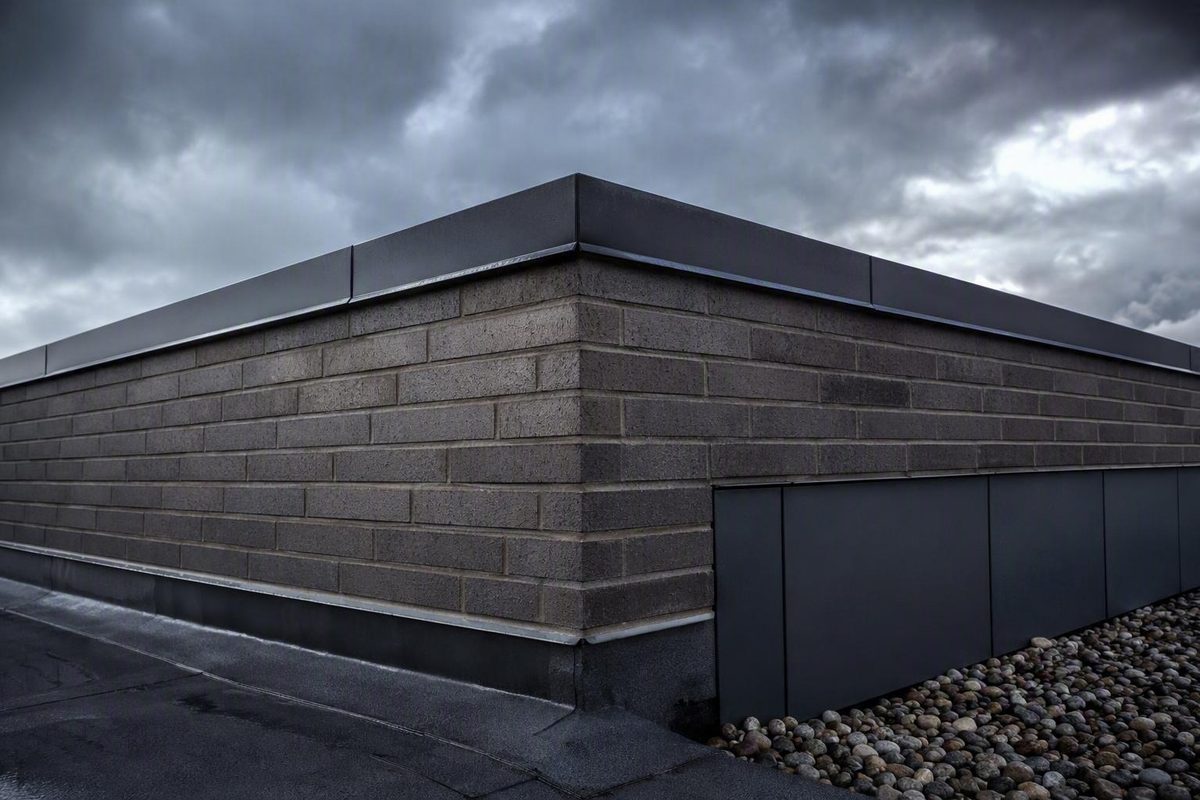
A parapet works as a complete roof-edge assembly—not merely as a wall above the roof.
A roof parapet wall is a wall or barrier extending above a roof edge. It may continue an exterior wall, party wall, fire wall, or another vertical element below the roof. Its performance depends on coordinating structure, waterproofing, coping, insulation, air control, drainage, and any safety or fire-related role.
The term parapet describes the wall’s position and form. It does not establish that the wall is a compliant guard, fire-wall extension, or fall-protection system. Those functions require project-specific verification.
Roof parapet wall: definition and quick component checklist
A parapet may look simple, but its most important work happens at the interfaces between the roof, wall, cap, drainage system, and control layers.
Rather than treating every component as part of one top-to-bottom stack, read the parapet detail by location:
At the wall top
- Coping or cap: Covers the parapet top and sheds water.
- Coping joints: Accommodate fabrication lengths and movement.
- Top-of-wall waterproofing: Protects the substrate below the coping.
- Parapet structure: May be masonry, reinforced concrete, metal construction, wood framing, or a coordinated combination.
At the roof-side transition
- Roof membrane upstand: Turns vertically from the roof onto the parapet.
- Membrane termination: Secures the upper edge against pull-away.
- Counterflashing or protected termination: Covers the membrane edge and directs water back onto the roof-side waterproofing.
- Roof insulation: Connects to or transitions around the parapet according to the roof-edge design.
At the exterior-wall transition
- Wall water-control layer: Connects the façade or wall assembly to the roof-edge flashing.
- Air-control connection: Limits airflow through gaps at the roof-to-wall junction.
- Thermal transition: Addresses discontinuities where the parapet structure crosses or interrupts insulation.
At drainage penetrations, where used
- Scupper or outlet: Carries water through the parapet.
- Overflow opening or other secondary route: Included where required by the governing drainage design.
At optional attachments
- Cleats, rails, screens, signs, anchors, or equipment supports: Require coordinated attachment and waterproofing details when present.
Not every parapet contains every listed component, and their arrangement varies with the roof and wall systems. The central point is that no element works in isolation. A sound wall can still admit water through an open coping joint, while a correctly installed membrane can fail if its upper edge is left exposed or inadequately secured.
What jobs can a parapet perform? Use a function-first decision table
Begin design review by stating what the parapet is intended to do. One wall may serve several functions, but each function must be addressed on its own terms.
| Intended function | Elements to coordinate | Project-specific verification |
|---|---|---|
| Architectural roof edge | Height, profile, coping, façade transitions, joints | Appearance, movement, exposure, specifications |
| Edge protection | Height, openings, continuity, support and attachments | Roof use, access, occupancy and applicable safety requirements |
| Limitation of fire spread | Wall continuity, roof intersection, penetrations and materials | Adopted code and applicable tested assembly |
| Equipment screening or privacy | Screen height, opacity, supports and access | Sightlines, loads, equipment clearances and project rules |
| Roof drainage | Outlets, scuppers, membrane transitions and conductors | Hydraulic design and any required overflow provisions |
| Architectural expression | Form, ornament, material and proportion | Support, water shedding and maintainability |
Architectural parapets, guards, and fire-wall continuations are not interchangeable. A low wall may define the roof edge without satisfying requirements applicable to a guard. Likewise, a parapet used as a fire-wall extension must preserve the required characteristics of the wall below and extend as required by the applicable code. General parapet references describe these possible roles but do not establish current compliance for a particular project. See the overview of parapet forms and functions.
Drainage arrangements also differ. Some roofs direct water through scuppers into gutters, conductor heads, or downspouts; others use internal drains or perimeter gutters. Where the governing code or drainage design calls for secondary drainage, the overflow route must be coordinated with the roof elevations and waterproofing.
Do not choose parapet height from a generic rule of thumb. Verify the locally adopted code and amendments, roof use and access, occupancy, construction type, applicable fire assembly, selected roof system, project specifications, and structural design. Trade-magazine summaries may describe common dimensions or uses, but they are not substitutes for governing documents. A general parapet-roof explainer illustrates the range of possible functions.
Common parapet forms and construction materials
Parapets are commonly described as:
- Plain: A generally continuous wall, often capped with coping.
- Embattled: A profile with alternating raised and lowered sections.
- Perforated: A parapet containing openings.
- Paneled: A wall articulated with recessed or projecting fields.
These categories can overlap. They describe architectural form, not structural capacity, fire resistance, or guard compliance.
Plain, flat-topped parapets are frequently associated with modern roof edges, but visual simplicity does not eliminate technical complexity. Curves, openings, steps, and ornament add transitions, yet even an unornamented wall still needs coordinated joints, waterproofing, insulation, and attachments.
| Material or system | Principal risks | Review focus |
|---|---|---|
| Brick or masonry | Absorption, cracking, open joints, freeze-thaw deterioration | Coping, flashing, movement and exposure |
| Reinforced concrete | Cracking, curing effects, waterproofing conflicts, thermal bridging | Reinforcement, waterproofing, attachments and insulation |
| Metal | Joint movement, fastener leakage and corrosion | Joint layout, fastening, coatings and transitions |
| Wood framing | Air leakage, condensation and wet sheathing | Air sealing, insulation, top sealing and drying strategy |
Brick or masonry
Masonry parapets are exposed at the top, outer face, and roof side. Coping and flashing help limit water entry, while joints must accommodate movement. Cracks, open coping joints, and saturated masonry can contribute to deterioration where freezing occurs.
Reinforced concrete
Concrete may form the parapet itself or continue the roof or wall structure. Its design needs to coordinate reinforcement, curing, waterproofing, and coping attachment. Where concrete crosses the insulation line, the roof-edge detail should also examine the resulting thermal bridge.
Metal
Metal may form a parapet or provide coping, flashing, cleats, and trim over another structure. Joint layout, fastening, waterproofing transitions, coatings, support, and exposure all influence performance. Material type alone does not establish durability or structural adequacy.
Wood framing
Wood-framed parapets need deliberate coordination among the roof membrane, wall water-control layer, air-control layer, insulation, sheathing, and sealed wall top. Interior-air leakage can carry moisture into a cold cavity, while poorly protected drying openings can admit exterior water.
A commercial roof-edge overview identifies brick, concrete, timber, and other systems while emphasizing that their structure, insulation, waterproofing, coping, flashing, and drainage must be coordinated. Its comparisons are general rather than engineering criteria. Review the material and detail overview.
Exposure, height, access, roof geometry, finishes, labor, loads, and maintenance conditions change the comparison.
Control the water at the top, face, and roof transition
Water management at a parapet follows a practical sequence:
- Shed water from the coping.
- Protect joints and exposed wall edges.
- Waterproof the substrate beneath the cap.
- Turn the roof membrane up the roof-side face.
- Secure and protect the membrane termination.
- Connect the wall water-control layer to the roof-edge flashing.
- Coordinate roof outlets and any required secondary drainage.
Coping protects the most exposed part of the wall, but covering the top is not enough. Slope, edge geometry, joints, attachment, and water shedding must follow the project specifications, selected product instructions, and any required engineering. A cap that appears flat should not be assumed to manage water adequately without a resolved detail.
Roof membranes commonly turn vertically up the parapet and terminate beneath protected flashing or coping.
Two examples—not universal dimensions
- Hammer & Hand’s contractor-authored wood-parapet guide recommends extending the roof membrane at least 12 inches above the roof plane, or higher where project specifications require it. It illustrates a mechanically fastened termination bar protected by fluid-applied counterflashing. See the Hammer & Hand parapet detail.
- A commercial parapet-system guide says many projects use an upstand of at least 150 millimeters, subject to roof design and local requirements. See the commercial roof-edge overview.
These figures come from different nonbinding sources. They are not interchangeable requirements.
The actual membrane rise and termination method must come from the selected roof system, project specifications, substrate conditions, finished roof elevations, and applicable requirements.
Penetrations through the parapet top increase the number of joints at its most exposed surface. Where rails, screens, signs, anchors, or equipment supports must attach, treat fastening and waterproofing as one design problem.
One possible drainage arrangement is:
sloped roof surface → scupper through the parapet → conductor head or gutter → downspout
That arrangement is only an example. The scupper and surrounding membrane transition must be detailed for the selected roof system. Any overflow opening or secondary route should be included only as required by the governing code or project drainage design, with its location and elevation established by that design.
Keep air, vapor, heat, and drying paths coordinated
A parapet can become wet even when its exterior flashing appears intact. It is exposed on several sides and contains roof-to-wall transitions through which rainwater or interior air may enter.
Four control functions should be considered separately:
- Bulk-water shedding: Uses coping, membranes, flashing, and drainage to manage rain and roof runoff.
- Air control: Limits airflow through joints, framing gaps, and penetrations.
- Vapor management: Addresses moisture movement by diffusion and the vapor profile of the assembly.
- Thermal continuity: Limits cold surfaces and concentrated heat flow at the roof edge.
These functions overlap but are not interchangeable.
Open framing paths, balloon framing, discontinuous sheathing, and service penetrations can connect indoor space to the parapet. Warm, moist interior air may then reach colder surfaces and condense. The roof and wall air-control layers therefore need a deliberate connection, while insulation should transition through or around the roof edge according to the assembly design.
For wood-framed parapets, Hammer & Hand recommends coordinating cavity insulation with the roof insulation, sealing the wall top below the cap, limiting connections to interior air, and ventilating cavities in the configurations shown in its guide. These are contractor-authored practices for a bounded type of construction, not universal instructions. See the source’s wood-parapet guidance.
Wood-framed recommendations should not be transferred unchanged to masonry, concrete, or metal-supported parapets. Those assemblies store, conduct, and release heat and moisture differently.
Inspection and diagnosis: warning signs and likely interfaces
Inspect a parapet by interface rather than treating all visible symptoms as evidence of one failure.
Parapet top
Look for:
- Open coping joints
- Loose or displaced coping
- Failed or deteriorated sealant
- Cracked caps or masonry units
- Corroded fasteners or metal edges
- Poorly sealed top penetrations
Exterior face
Check for:
- Cracks in masonry, concrete, coatings, or cladding
- Staining below joints and attachments
- Efflorescence
- Spalling or surface deterioration
- Corrosion staining
- Open façade transitions
It does not, by itself, identify the original entry point.
Roof-side membrane termination
Look for:
- Membrane pull-away
- Loose termination components
- Open flashing laps
- Wrinkles, punctures, splits, or unprotected edges
- Deterioration at corners and changes in height
Pull-away near the top of an upstand directs attention to the termination and surrounding substrate, but further investigation may be needed to determine why movement occurred.
Penetrations and attachments
Examine rails, screens, signs, anchors, conduits, and equipment supports for loose fasteners, cracked sealant, deformation, corrosion, and visible water paths.
Insulation and air-control transition
Where the assembly is accessible, look for wet or deteriorated sheathing, compressed insulation, open air-control joints, interior staining, and service penetrations connected to conditioned space.
Drainage openings
Check scuppers, conductor heads, gutters, downspouts, and any overflow openings for debris, deformation, corrosion, and deterioration at membrane transitions.
Visible symptoms rarely establish the complete cause. Water may travel through cavities before emerging. Concealed moisture, unstable masonry, deteriorated attachments, or affected fire-rated construction may require investigation by qualified roofing, envelope, structural, or fire-protection professionals.
Preconstruction and reroofing verification checklist
Start by classifying the parapet as an architectural edge, guard-related barrier, fire-wall continuation, equipment screen, drainage edge, or combination. Then identify who must resolve each interface.
| Team member | Typical coordination focus |
|---|---|
| Architect or envelope designer | Functions, dimensions, control layers and specifications |
| Structural engineer | Support, reinforcement, connections and applicable loads |
| Roofing contractor | Membrane upstand, corners, termination and scupper transitions |
| Façade or masonry contractor | Wall water control, joints and exterior transitions |
| Sheet-metal contractor | Coping, joints, flashing, scuppers and conductor heads |
This table is a coordination prompt, not a universal allocation of contractual responsibility. Actual responsibilities belong in the project documents.
Before construction or close-in, confirm:
- Every intended parapet function
- Current local code and amendments
- Roof occupancy and access conditions
- Applicable tested fire assembly
- Project-specific structural and attachment design
- Selected roof-system instructions
- Project specifications
- Coping geometry, joints and attachment
- Primary drainage and any required overflow arrangement
- Roof and wall insulation transition
- Membrane upstand, termination and protection
- Wall water-control and air-control transitions
- Scuppers, penetrations, corners and changes in height
- Façade and roof-edge interfaces
For reroofing, compare the existing and proposed finished roof elevations. The project team should determine which existing components remain compatible with the new geometry.
Parapet height, thickness, membrane rise, fire resistance, coping attachment spacing, and similar dimensions cannot be selected from a general guide. They must be established for the jurisdiction, structure, roof system, materials, drainage design, tested assemblies, and actual exposure.
Frequently asked questions
What is the difference between a parapet and a guardrail?
A parapet is a wall or barrier extending above a roof edge. A guard is a safety assembly intended to reduce the risk of falls at an exposed edge. A parapet can serve that function only when its dimensions, openings, continuity, structural capacity, and attachments satisfy the requirements applicable to the building and roof use. General articles may discuss fall protection as a possible parapet function, but they do not establish compliance. See the trade overview of parapet uses.
Can a roof parapet hide mechanical equipment?
Yes. A parapet can screen rooftop equipment from selected views. The design review should consider sightlines, support, equipment clearances, service access, drainage, and attachment penetrations. Screening should be coordinated with the equipment and roof design rather than treated only as a taller architectural wall.
Why do masonry parapets develop efflorescence or freeze-thaw damage?
Open coping joints, cracks, failed flashing, or drainage problems may contribute, but the visible damage does not necessarily reveal the original moisture source.
Should the roof membrane run over the top of the parapet?
Not automatically. Roof membranes commonly turn up the roof-side face and terminate beneath protected flashing or coping. Some assemblies use a membrane or separate waterproofing layer across the wall top, while others use a different transition beneath the cap. Follow the selected roof-system instructions and project detail rather than extending one membrane over every parapet by default.
The final review can be reduced to five steps:
- Classify the function: State every role the parapet must perform.
- Map the layers: Trace structure, water, air, vapor, and insulation through the roof edge.
- Protect the top and termination: Resolve coping, joints, membrane upstand, fastening, and flashing.
- Verify drainage: Coordinate primary outlets and any required overflow route.
- Confirm the project requirements: Check the governing code, structural and fire design, roof-system instructions, envelope design, and specifications for the actual building.