
Manufactured Stone Veneer Is a Wall System, Not Just a Finish
How to detail manufactured stone veneer, from WRB and lath to mortar, flashing, clearances, movement joints and product verification.
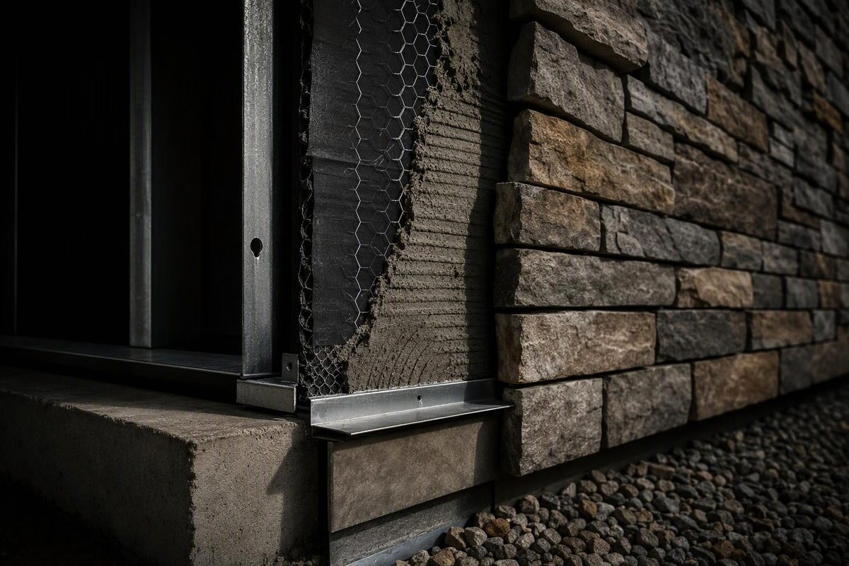
Manufactured stone veneer is a non-load-bearing, cast concrete facing made to resemble natural stone. Cement, normal- or lightweight aggregate, water, admixtures and pigments are cast in molds; the finished units are bonded to a prepared wall with cementitious mortar. ASTM C1670/C1670M establishes minimum product requirements, while ASTM C1780 covers installation of cement-based adhered veneer. The latter expressly does not cover every flashing or moisture-management requirement, so specifying “install per ASTM C1780” does not complete the wall design (ASTM C1670/C1670M-21b; ASTM C1780-23a).
The useful distinction is not simply “real versus fake stone.” It is assembly type:
| Cladding | Material | Attachment | Principal design consequence |
|---|---|---|---|
| Manufactured stone veneer | Molded cementitious units | Adhered with mortar | Thin finish, but needs a complete drainage, substrate and bond design |
| Natural thin-stone veneer | Quarried stone cut thin | Adhered with mortar | Similar wall concept, but use natural-stone requirements rather than assuming the MSV standard applies |
| Full-bed natural stone veneer | Thick quarried stone | Usually anchored, with a cavity and structural support | Requires a support ledge or foundation and a separate gravity/lateral attachment strategy |
ASTM C1780 directs adhered natural stone to ASTM C1242 rather than treating it as manufactured veneer. For a broader comparison of adhered and anchored systems, see masonry veneer types, loads and drainage.
What the exterior wall actually contains
On a typical framed exterior wall using metal lath, the layers run approximately as follows, from inside to outside:
- Framing and structural sheathing
- Primary water-resistive barrier (WRB), integrated with opening and transition flashings
- A second WRB layer for the conventional lath-and-scratch-coat path, or another code- and manufacturer-compliant drainage configuration
- Corrosion-resistant, self-furring lath fastened into framing—not merely into sheathing
- Nominal 1/2-inch (13 mm) mortar scratch coat, fully engaging the lath
- Cementitious setting bed with full contact to the back of each unit
- Manufactured stone units and, for jointed profiles, pointing mortar
The current CMHA guide specification calls for two WRB layers on light-frame walls with lath and scratch coat, but one layer for its cement-board assembly. It also describes a drainage space or system of at least 3/16 inch (5 mm) where shown or required, and requires the WRB to be integrated with windows, doors, penetrations and cladding transitions (CMHA guide specification). These are assembly choices, not interchangeable notes; the drawings should identify the selected path.
A common mistake is to draw the stone profile at the face of wall and leave everything behind it to a generic specification. That misses the conditions most likely to determine performance:
- head flashing above openings;
- sill-pan and jamb integration;
- kick-out flashing where a roof terminates at the wall;
- base flashing or weep screed;
- transitions to siding, stucco or brick;
- penetrations, electrical boxes and hose bibs;
- continuity over continuous insulation; and
- movement joints at changes in backing and other anticipated movement locations.
MSV is not waterproof. Water that reaches the WRB must be collected and directed back outside; reverse laps can instead send it behind the drainage plane. Published forensic examples connect poor WRB/flashing integration with wet and swollen sheathing, cracking and veneer detachment. They also identify incomplete lath embedment, unaccommodated differential movement and voids behind units as recurring failure conditions (IIBEC).
Dimensions that change the elevation and section
MSV does not need the cavity and shelf support associated with full-bed anchored stone, but it is not dimensionless. Coordinate the combined projection of drainage material, lath, scratch coat, setting bed and the selected stone profile. That depth affects:
- window and door jamb extensions;
- drip-cap projection beyond the stone face;
- sill and water-table overhangs;
- returns at openings;
- outlet-box depth;
- roof-to-wall clearances; and
- termination against adjacent claddings.
Obtain the manufacturer’s actual minimum and maximum unit thickness rather than drawing a generic veneer line. Require purpose-made corner units where the design is intended to read as full-depth stone. A cut field unit at an exposed outside corner can reveal the cementitious body and produce an unconvincing thin edge.
Keep the finish clear of splashback and moisture reservoirs. CMHA’s current guide specification calls for framed exterior-wall installations to stop 4 inches (102 mm) above soil and 2 inches (51 mm) above pavement not supported by the wall foundation (CMHA guide specification). CMHA publishes different minimums for some concrete or masonry substrates and for walking surfaces supported by the same foundation, so the section must match the actual substrate and paving condition rather than repeating one clearance everywhere (CMHA installation checkpoints). Exterior veneer at a foundation also needs separate verification of grade exposure, substrate and system approval; see what to verify at a stone-veneer foundation.
Specify the product and the bond separately
A defensible submittal should establish more than color and profile. Require:
- evidence that the units comply with ASTM C1670/C1670M;
- the current manufacturer installation instructions;
- an applicable evaluation report where the approval path relies on one;
- unit thickness, saturated unit weight and total assembly weight;
- compatible WRB, drainage, lath, fastener, scratch-coat and setting-bed products;
- accessory shapes and corners;
- a sample panel showing color range, pattern, joint width and tooling; and
- details for openings, base, top, corners, penetrations and material transitions.
One current ICC-ES report, for example, describes its evaluated MSV as precast concrete, non-load-bearing exterior veneer and limits the reported saturated unit weight to 15 psf (73.2 kg/m²); it explicitly excludes scratch-coat and setting-bed weight from that figure. It also requires the supporting construction to carry the veneer system and the installation to follow the report, manufacturer instructions and applicable code (ICC-ES ESR-3151). That distinction matters when checking framing, fasteners, seismic wall weight or attachment through continuous insulation.
Do not substitute a familiar masonry mortar by name alone. The 2025 CMHA guide specification distinguishes scratch/pointing mortars from the setting bed and, for its TMS 402/602-22 path, calls for a prepackaged modified setting mortar meeting ANSI A118.4 or A118.15. The appropriate product still depends on the substrate and approved system; polymer-modified mortars are not one interchangeable category.
Field checkpoints before the stone hides the work
Inspection is most valuable before the face units go on. Confirm that:
- sheet WRB laps shed downward and flashings discharge outward;
- lath fasteners penetrate framing at the required spacing and depth;
- lath laps and corners are continuous;
- the nominal 1/2-inch scratch coat fully engages the lath and is scored;
- a dried scratch coat is dampened without leaving standing water;
- setting mortar gives full coverage and squeeze-out, without void pockets;
- bumped units are removed and reset rather than pushed back into partially set mortar; and
- movement joints shown in the documents remain free of rigid mortar.
CMHA’s installation checkpoints address these fastening, scratch-coat and unit-setting requirements, including fastening into framing, nominal 1/2-inch scratch-coat thickness, full mortar coverage and resetting disturbed units (CMHA installation checkpoints).
The 2024 IRC sends adhered masonry veneer to TMS 402 design provisions and permits installation under its prescribed section, TMS 602 or the manufacturer’s instructions (2024 IRC R703.12). Projects must use the code edition and amendments actually adopted by their jurisdiction. CMHA publishes separate installation-guide editions coordinated with the 2021-and-earlier codes and with the 2024 codes (CMHA installation guide).
Finally, plan cutting as a safety operation. Sawing material that contains crystalline silica can generate respirable dust. OSHA’s construction table specifies integrated water delivery for handheld power saws and adds respiratory-protection requirements for certain durations and enclosed conditions; the employer must implement the applicable exposure-control method rather than rely on an ordinary dust mask (OSHA 29 CFR 1926.1153).
Manufactured stone veneer succeeds when it is treated as the visible layer of a coordinated wall. Product selection establishes appearance; the substrate, drainage, flashing, mortar, attachment and movement details determine whether that appearance stays attached and the wall behind it stays dry.