
Inside the Material Stack of an ICF Wall
See what an ICF wall is made of, from EPS forms and webs to concrete, rebar, bucks, membranes and finishes, plus what drawings must specify.
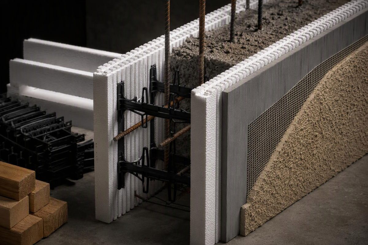
An insulated concrete form wall combines stay-in-place insulating forms, connecting webs, a cast-in-place concrete core and reinforcing steel. Opening bucks, embeds, membranes and finishes complete the assembly. The reinforced concrete carries the principal structural loads; the forms contain the pour, remain as insulation and support coordinated finishes.
“ICF wall” alone does not establish the concrete-core thickness, insulation thickness, reinforcement, fastening capacity, waterproofing or finish attachment. The drawings and specifications must define each part for the selected system.
Select a component to see its material, function and required drawing information.
ICF Material Selector
Choose the part being detailed. The coordination requirements appear beside it.
Form Faces
Sources: 2021 IRC §§ R608.4–R608.5 and R316.4; Building Science Corporation; ICC-ES ESR-1147. Product-specific values remain product-specific.
A Typical ICF Wall Has Seven Material Layers
| Component | Common Material | Primary Job | Documents Must Define |
|---|---|---|---|
| Form faces | Expanded polystyrene (EPS) | Contain concrete and remain as insulation | Thickness, tested system and thermal value |
| Webs or cross-ties | Molded plastic; alternatives vary | Space faces, support bars and provide fastening flanges | Spacing, flange locations and fastener loads |
| Core | Cast-in-place concrete | Carry structural loads | Thickness, strength, exposure and mix criteria |
| Reinforcement | Deformed steel bars | Supply tensile capacity and connect construction | Size, spacing, laps, cover and opening bars |
| Opening bucks | Wood, plastic, metal or composite | Stop the pour and receive frames | Dimensions, anchorage and flashing interfaces |
| Interior protection | Usually gypsum board | Protect foam and finish the interior | Approved thermal barrier and attachment detail |
| Exterior control layers | Membranes, flashing, drainage and cladding | Control water, weather and physical damage | Compatible products and continuous transitions |
The exact stack varies by manufacturer. Product evaluation reports, engineering and the locally adopted code take precedence over a generic ICF detail.
EPS Faces Contain the Pour and Remain as Insulation
Most North American ICFs use molded EPS faces. A common configuration has roughly 2½ inches (64 mm) of EPS on each side of the concrete, although dimensions and thermal properties vary by product. Building Science Corporation describes a representative 9-inch ICF form containing 5 inches total of EPS as approximately R-20 whole-wall. That is an assembly example, not a universal ICF rating (Building Science Corporation).
EPS performs three jobs during and after construction:
- It contains the fresh concrete.
- It provides continuous insulation across most of the wall.
- It creates the surface around which finishes, penetrations and openings must be detailed.
The foam does not replace the concrete wall or its reinforcement. It also cannot remain exposed where the code requires protection. Section R608.4 of the 2021 IRC requires rigid-foam stay-in-place forms to have an approved exterior wall covering and directs the interior face to the code’s foam-plastic protection provisions (2021 IRC Chapter 6).
Section R316.4 generally requires at least ½-inch (12.7 mm) gypsum wallboard, a 23/32-inch wood structural panel or another qualifying thermal barrier unless an exception applies (2021 IRC R316.4). The locally adopted code and the selected system’s evaluation report govern a particular project.
Cement-Bonded Forms Are a Separate System Type
Not every ICF is an EPS block. The 2021 IRC also permits form materials made from composites of cement and wood chips or cement and foam insulation (2021 IRC Chapter 6). One commercial alternative uses mineralized wood fiber bonded with Portland cement rather than two EPS panels (Nexcem).
Dimensions, insulation inserts, concrete geometry, finish attachment and moisture detailing differ from conventional EPS systems. A cement-bonded form should not be substituted for an EPS system under a generic ICF specification.
Plastic Webs Set the Cavity and Receive Some Fasteners
Plastic webs connect the form faces and help the assembly resist pressure while the concrete is fluid. They commonly support horizontal reinforcing bars and provide recessed flanges for screws.
In one evaluated system, high-impact polystyrene channel inserts occur at 8 inches (203 mm) on center and have 1⅝-inch-wide flanges recessed ¾ inch behind the EPS surface. Those dimensions are product-specific, not an industry-wide stud layout (ICC-ES evaluation report ESR-1147).
That distinction affects elevations, sections and finish schedules. Lay out the wall to the manufacturer’s module so usable webs remain beside corners and openings. Select finish fasteners from the system’s published capacities, required penetration and design wind pressure rather than treating a plastic flange as a wood stud.
Cabinets, guards, canopies and other concentrated loads may require attachment to the concrete core or engineered blocking. Web locations should be recorded before finishes conceal them.
Webs can help position reinforcing bars, but they do not establish the structural reinforcing schedule. The wall design does.
Concrete-Core Thickness Is Not Overall Wall Thickness
The core is cast-in-place concrete, usually reinforced horizontally and vertically. Its thickness is the clear distance between the inside faces of the forms, not the wall’s overall dimension.
Overall wall thickness = exterior form face + concrete core + interior form face.
Specify all three dimensions. “11-inch ICF” is ambiguous if the drawings do not identify whether 11 inches describes the overall form width or the concrete cavity.
The concrete must flow around bars, webs, corners and bucks without segregating or leaving voids. For work under its scope, the 2021 IRC requires concrete placed in stay-in-place forms to have a slump greater than 6 inches (152 mm). It calls for internal vibration unless an approved self-consolidating mix with a slump of at least 8 inches (203 mm) is specifically designed for placement without it.
The same section limits aggregate according to cavity width and clear reinforcing-bar spacing. It sets a minimum 28-day compressive strength of 2,500 psi (17.2 MPa), subject to higher project requirements (2021 IRC R608.5).
Those provisions are not a ready-mix order. The engineer, concrete supplier and ICF manufacturer must reconcile strength, aggregate size, slump, admixtures, placement rate and consolidation with the actual wall geometry. Adding water at the pump to make a poorly proportioned mix flow is not a substitute for an approved mix design.
Reinforcing Steel Must Be Detailed for the Actual Loads
Rebar size and spacing depend on wall height, gravity and lateral loads, openings, soil pressure, seismic conditions and restraint. The drawings must detail footing dowels, horizontal and vertical bars, laps, lintels, jamb bars, top connections and concrete cover.
The principles are the same as for other reinforced concrete, but inspection and placement require additional planning because the foam conceals both faces of the pour. Bars also have to fit around webs, sleeves and opening reinforcement while preserving the clearances needed for concrete placement.
The form manufacturer’s bar supports can assist installation. They do not replace an engineered reinforcing design or inspection before concrete placement.
Bucks and Embeds Must Be Resolved Before the Pour
Door and window bucks may be wood, plastic, metal or a proprietary composite. They must withstand concrete placement and provide a defined attachment surface for the frame.
Where required by the code official, the evaluation report for one ICF system calls for wood framing in contact with concrete to be pressure-treated or naturally durable and attached with specified corrosion-resistant fasteners (ICC-ES ESR-1147). Requirements depend on the selected assembly and exposure.
Coordinate these items before concrete placement:
- actual rough-opening dimensions and sill elevations;
- lintel and jamb reinforcement;
- frame anchorage into the buck or concrete;
- sill pans, flashing and air-barrier transitions;
- sleeves for plumbing, electrical, ventilation and utilities;
- anchor bolts, ledger connectors, hold-downs and beam pockets.
Moving a penetration after placement means cutting foam and drilling reinforced concrete. A coordinated sleeve avoids that work and gives the air- and water-control layers a defined transition.
Membranes and Finishes Complete the Envelope
ICF supplies insulation, but it does not eliminate rain-control detailing. Building Science Corporation notes that the concrete core can act as the field air barrier while penetrations still require sealing. Its example assembly also uses furring to create a drainage and ventilation gap behind cladding (Building Science Corporation).
At windows, roofs, floors and foundations, the documents should show exactly how the air and water layers cross each assembly break.
Below grade, specify dampproofing or waterproofing appropriate to the site conditions, along with drainage and any required protection layer. Verify that membranes, primers, sealants and adhesives are compatible with the selected form.
One ICC-ES report, for example, requires below-grade products to be free of solvents, hydrocarbons, ketones and esters that would adversely affect its EPS (ICC-ES ESR-1147). That is a product-specific requirement, not a universal compatibility list for every ICF.
Above grade, stucco, adhered finishes, siding and anchored masonry require different substrates and attachment strategies. For brick, the cavity, flashing, weeps, shelf support and ties still need complete brick-veneer detailing. The ICF face is not itself a drainage cavity or structural support for masonry.
Compare Systems Beyond Nominal R-Value
Before selecting a form system, compare its available concrete-core widths, corners and lintel units. Confirm the insulation thickness and verified whole-wall thermal performance rather than relying only on a nominal foam value.
Web spacing, flange width and published fastener capacities affect interior and exterior finish attachment. Reinforcement clearance and concrete-placement requirements affect constructability. Opening bucks, floor connections and available embeds affect detailing at nearly every transition.
The review should also cover compatible waterproofing, air barriers and finishes; current evaluation reports; fire-tested assemblies; local approval; termite inspection or protection where applicable; installer familiarity; and access to manufacturer technical support.
A complete ICF specification names the form system while separately defining the structural concrete, reinforcement, embeds, opening materials and envelope layers. That coordination turns insulating forms into a complete reinforced-concrete wall assembly.