
How to Choose a Steel Floor System Without Guessing at Span or Performance
Start with the application and complete floor assembly, then evaluate loads, clear span, spacing, depth, serviceability, MEP routing and installed cost.
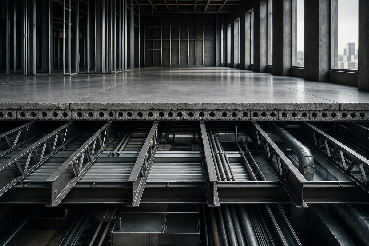
“Metal floor joists” sounds like one product category. It is not. The phrase may refer to cold-formed steel C-joists, open-web steel joists, light-gauge steel trusses, proprietary open-web systems, or steel members made specifically for exterior decks. Those products differ in geometry, structural behavior, floor depth, service access, exposure requirements, connections, fabrication, erection, and supporting documentation.
This guide is therefore a preliminary system-selection overview, not a span chart, installation manual, code interpretation, or substitute for structural design. The available sources include manufacturer literature, retailer listings, an industry webinar page, and a third-party reproduction of one jurisdiction-specific code provision. They do not include the complete primary standards, official model-code text, full design manuals, complete span tables, product reports, or tested fire and acoustic assemblies needed to approve a project.
A useful comparison begins with the application and the complete floor assembly. Only then should the project team evaluate loads, clear span, spacing, depth, serviceability, connections, mechanical routing, documentation, and total installed cost.
What “metal floor joists” can mean
Metal floor joist is best treated as an umbrella search term rather than a standardized product name. Before comparing spans or prices, identify the member form, intended application, design method, and documents governing its use.
A cold-formed steel C-joist is a relatively thin steel section formed into a C-shaped profile. Its web is substantially solid except for manufacturer-provided punch-outs or other documented openings. Available depths, flange widths, steel thicknesses, material properties, accessories, and opening rules vary by product family.
An open-web steel joist generally uses top and bottom chords connected by internal web members. Depending on the system, it may be governed by industry specifications, manufacturer documents, project design criteria, shop drawings, and erection requirements.
A light-gauge steel truss or proprietary open-web floor member also has chords and internal webs, but it should not automatically be treated as interchangeable with every other open-web joist. The open-web categories below are therefore conceptual groupings, not one standardized product class.
An exterior steel deck joist is intended for outdoor deck framing. It may have a proprietary section, finish, connection system, span chart, installation guide, warranty, and compliance report. Its exposure conditions and supported decking can differ substantially from an interior occupied floor.
| System | Member form | Typical application | Relative floor depth | MEP access | Documentation to verify |
|---|---|---|---|---|---|
| Cold-formed C-joist | Solid C-shaped section, often with standard punch-outs | Repetitive interior floor framing where limited depth is important | Generally shallower than many open-web options | Standard openings may suit wiring and some small pipes; large ducts are more restrictive | Current product tables, section properties, approved uses, opening rules, bracing, bearing, and connection details |
| Open-web steel joist | Chords connected by open web members | Interior floor bays where service integration, stiffness, or longer clear bays influence selection | Often deeper, although geometry varies | Open spaces may simplify routing larger services | Applicable product specifications, project design criteria, shop drawings, connection forces, erection requirements, and vibration criteria |
| Light-gauge truss or proprietary open-web member | Prefabricated chords and internal webs in a manufacturer-specific arrangement | Project-specific interior floors and prefabricated systems | Product- and project-specific | Open geometry can improve service access, subject to web and connection locations | Manufacturer design basis, calculations, shop drawings, fabrication limits, lifting and bracing requirements, and connection design |
| Exterior steel deck joist | Proprietary solid or formed deck-framing member | Exterior decks and similar documented outdoor uses | Product-specific | Usually secondary to deck layout and exterior detailing | Exterior span charts, coating and exposure requirements, installation instructions, compliance report, and warranty |
A standard C-joist punch-out may accommodate wiring, sprinklers, or some smaller pipes, but it should not be assumed to accept an HVAC duct. Open-web framing generally offers more usable service space, although ducts and pipes must still avoid webs, bearings, connections, fire protection, and required access zones. A commercial comparison describes these broad geometry and routing differences, but its span, depth, and price ranges are vendor estimates—not allowable design limits (US Frame Factory’s joist-and-truss comparison).
Exterior products require equally careful classification. One retail listing, for example, describes a 2-by-6-inch, 16-foot, 16-gauge steel member specifically as deck framing. That description does not establish approval for an interior occupied floor (Home Depot’s FORTRESS Evolution listing).
A joist sold for an exterior deck is therefore not automatically suitable for an interior floor. Approved application, exposure protection, loads, deflection, connections, fire performance, and the supported assembly all require verification.
Do not transfer a benefit, span range, price, opening rule, or installation detail from one steel framing category to another.
Choose the system by application, not by material alone
System selection often begins before an individual joist is sized. Floor-to-floor height, duct dimensions, bay planning, erection access, architectural layout, exposure, and procurement constraints can eliminate an otherwise plausible option.
Three preliminary applications provide a useful starting point.
For a depth-constrained interior floor, a cold-formed C-joist may be plausible. Its relatively compact profile can help where the ceiling cannot drop and major ducts can run elsewhere. Final suitability still depends on documented strength, deflection, vibration behavior, bearing, bracing, connections, and assembly requirements.
For a longer-span or MEP-intensive interior floor, an open-web system may be the more plausible starting point. Its geometry can provide routes through the structural zone, potentially reducing the need for a separate service zone below.
For an exterior deck, begin with a product expressly documented for exterior deck framing. Confirm that its span charts cover the proposed loading and spacing, its finish is suitable for the actual exposure, and compatible beams, ledgers, fasteners, blocking, and decking details are available. One marketed deck system links separate installation guidance, span charts, and a compliance report, illustrating the type of product-specific documentation that should be reviewed rather than inferred from a retail description (New Castle Steel Deck Joist Plus listing).
Use this matrix during concept design:
| Decision factor | Cold-formed C-joist | Open-web interior system | Exterior deck joist |
|---|---|---|---|
| Clear span | Screen against the exact product table | Establish through the applicable system design and project criteria | Use only the product’s exterior span chart |
| Available structural depth | Often a useful starting point where depth is limited | May require more depth; coordinate with floor-to-floor height | Product-specific |
| Duct size | Large ducts may require soffits, separate service zones, or another system | Open geometry can improve routing, but routes still require coordination | Usually not the primary selection issue |
| Point and line loads | Require explicit analysis and documented load transfer | Require project-specific analysis and coordination with web geometry | Must be covered by product documentation and deck design |
| Exposure | Verify environmental conditions and coating | Verify environmental conditions and specifications | Must be approved for the actual exterior environment |
| Erection constraints | Repetitive members may be easier to handle, but temporary restraint still matters | Prefabricated or longer pieces may affect access, lifting, and sequencing | Check access, storage, fastening, and weather limitations |
| Lead time | Depends on section availability and fabrication | Custom design and fabrication may require earlier release | Depends on proprietary system availability |
| Vibration target | May govern depth, spacing, or assembly | Can remain a major criterion despite apparent stiffness | Verify serviceability criteria for deck use |
| Total installed cost | Include accessories, sheathing, ceilings, labor, and engineering | Include connections, fabrication, delivery, lifting, and service coordination | Include the complete framing package, freight, finish, and decking interfaces |
| Documentation | Product tables and assembly details | Design criteria, calculations, shop drawings, connection documents, and erection plans | Exterior span tables, installation instructions, compliance documents, and warranty |
Commercial literature often presents C-joists as shallower and open-web framing as better suited to longer bays and larger services. Those patterns are orientation only. They are not allowable ranges or design limits, and they do not establish that one system will outperform another under a particular project’s loads, depth constraints, or serviceability criteria.
The decisive question may not be “Which joist is strongest?” It may be whether a main duct can cross the bay without lowering the ceiling, whether the floor can meet its vibration target, or whether the structure fits within the permitted floor-to-floor height. The Steel Joist Institute’s educational material similarly treats spacing, depth, floor-to-floor height, connections, vibration, and cost as related system decisions rather than isolated member checks (SJI’s open-web floor-design overview).
The inputs that actually control joist selection
A floor joist cannot be selected responsibly from span alone. At minimum, the engineer or manufacturer needs to know what the floor carries, how the joists are supported, how closely they are spaced, how the assembly transfers load, and how much movement is acceptable.
Dead load is the weight of permanent floor components, including the joists, subfloor, topping, flooring, ceiling, fixed construction, and other permanently attached materials.
Live load is temporary loading associated with occupants, furniture, movable objects, and the use of the space. Live-load requirements vary by occupancy and do not account for every concentrated, line, equipment, or special load.
Essential selection inputs include:
- Occupancy and intended use
- Complete dead load
- Required live load
- Concentrated and line loads
- Clear unsupported span
- Single-span or multiple-span support arrangement
- Joist spacing
- Maximum permitted structural and assembly depth
- Member section, including web depth and flange geometry
- Steel thickness and material properties
- Bearing width and support material
- Joist orientation and load path
- Hangers, clips, welds, screws, bolts, or other connections
- Web-stiffener and load-transfer requirements
- Required blocking, bridging, and bracing
- Static deflection criteria
- Vibration or floor-comfort criteria
- Diaphragm and lateral-load requirements, where applicable
- Required fire, acoustic, and environmental performance
Increasing span generally increases structural and deflection demand. Increasing spacing generally increases the tributary floor width carried by each joist. Changing depth, flange geometry, steel thickness, material properties, or support configuration can change capacity and stiffness. These relationships explain why the inputs matter; they are not sizing rules.
Clear span is not necessarily overall member length. The member may extend over bearings, into tracks, or across more than one bay.
Single span:
[Support] <------ clear unsupported span ------> [Support]

Double span:
[End support] <--- span A ---> [Intermediate support] <--- span B ---> [End support]
A double-span arrangement includes an intermediate support and behaves differently from two unrelated single-span members. A multiple-span table should be used only when the actual support and connection conditions match its assumptions.
Bathtubs, bearing walls, stairs, mechanical equipment, posts, storage systems, and similar conditions may apply load to one joist or a limited part of the floor. These conditions require explicit project-specific analysis and documented load-transfer details rather than being averaged into a general floor-wide value.
A vendor tool demonstration shows the kinds of inputs a preliminary selector may request: dead load, live load, deflection limit, single- or double-span configuration, spacing, joist depth, clear span, flange size, and material strength. Its example uses 10 psf dead load, 40 psf live load, and L/360, but these are demonstration inputs—not universal residential or hotel requirements (US Frame Factory tool demonstration).
A separate page from the same vendor contains contradictory wording: its narrative reverses dead and live loads, while its residential table link is labeled 10 psf dead load and 40 psf live load. The table label can describe that source-specific example, but neither value should be adopted without confirming occupancy, jurisdiction, finishes, partitions, and the rest of the assembly.
Fill-in project-input checklist
Provide this information to the structural engineer or manufacturer:
- Project and floor location: ____
- Occupancy and use: ____
- Applicable jurisdiction and design basis: ____
- Floor dead load, with component breakdown: ____
- Required live load: ____
- Concentrated, line, wall, equipment, stair, and post loads: ____
- Clear span for each bay: ____
- Support configuration—single, double, multiple, or cantilever: ____
- Support material and available bearing: ____
- Proposed joist spacing: ____
- Maximum joist depth: ____
- Maximum total floor-ceiling depth: ____
- Subfloor, topping, finish, and ceiling: ____
- Required deflection criteria: ____
- Vibration or floor-comfort target: ____
- Duct, pipe, conduit, and cable requirements: ____
- Fire-resistance requirement: ____
- Acoustic target: ____
- Interior, wet, exterior, coastal, or corrosive exposure: ____
- Erection, lifting, access, and delivery constraints: ____
- Proposed product family, if known: ____
How to use span tables and sizing tools without misusing them
How far can metal floor joists span? There is no reliable universal maximum. Allowable span changes with the exact product, loads, spacing, member section, material properties, support configuration, bearing, connections, bracing, and serviceability criteria.
Open-web systems may be designed for a particular project, while proprietary exterior joists may be limited to narrowly documented assemblies.
Use this preliminary workflow:
- Identify the category and product family. Determine whether the member is a cold-formed C-joist, an open-web joist, a light-gauge or proprietary truss, or an exterior deck product.
- Confirm the table’s application and load basis. Check occupancy, dead load, live load, concentrated loads, load combinations, and whether the table applies to floors, attics, decks, or another use.
- Select the correct support configuration. Match single-span, multiple-span, cantilever, or continuous conditions.
- Match spacing and depth constraints. Use the actual on-center spacing and verify that the complete assembly fits the available zone.
- Check strength and deflection. A strength-qualified row may still fail the applicable movement criterion.
- Review bearing and accessories. Confirm bearing length, track, hangers, clips, stiffeners, blocking, strapping, bridging, and fasteners.
- Review service routes. Verify which factory openings are usable and whether any field modification is permitted.
- Verify connections and load transfer. Joist reactions must reach the supporting structure through documented details.
- Check the complete assembly. Include sheathing attachment, ceiling restraint, fire protection, acoustic layers, and diaphragm conditions.
- Obtain project-specific review. Coordinate the selection with current product documents, applicable local requirements, and the responsible structural professional.
A table row is valid only under its stated assumptions. A longer span in an unrelated table does not grant permission to use that member. If the table assumes another spacing, load, support condition, deflection limit, or assembly, it answers a different question.
Online tools can screen options, but an output is not structural approval when the tool does not disclose its calculations, safety factors, governing provisions, connection checks, and complete assumptions.
The supplied manufacturer pages link to design tables but do not reproduce enough numerical information to publish an independent span chart here. ClarkDietrich, for example, lists C-joist offerings in 8-, 10-, 12-, and 14-inch depths; 18-, 16-, 14-, and 12-gauge designations; several flange widths; and 12-, 16-, 19.2-, and 24-inch on-center spacing options. These are manufacturer-specific offerings, not universal recommendations (ClarkDietrich C-Joist product information).
Common span-table errors
- Swapping dead load and live load
- Confusing clear span with overall member length
- Ignoring walls, equipment, stairs, posts, and other localized loads
- Reading the row for the wrong on-center spacing
- Using a single-span row for a multiple-span condition, or vice versa
- Checking strength while overlooking deflection or vibration
- Assuming factory punch-outs permit any service penetration
- Omitting required bearing, connections, stiffeners, blocking, or bracing
- Using an obsolete table after a product or design basis has changed
- Applying an exterior deck chart to an interior occupied floor
The complete floor assembly: track, connections, stiffeners, blocking, and bracing
Selecting a joist section does not complete the floor design. The joist must transfer load into its supports, remain stable during construction and service, receive the required flange restraint, support the subfloor, and integrate with openings, walls, ceilings, and lateral systems.
A cold-formed floor assembly may include:
- Structural track used as a rim or band enclosure
- Joist hangers or specified support clips at girders and headers
- Web stiffeners at bearings, joist ends, or point-load locations
- Headers and trimmers around openings
- Solid blocking between joists
- Continuous straps or other bridging
- Specified screws, bolts, welds, or anchors
- Structural sheathing or subfloor
- Topping, finish flooring, insulation, and ceiling
- Bearing plates, ledgers, or other support details
- Temporary erection bracing
- Diaphragm chords, collectors, and connections where required
ClarkDietrich identifies structural track, hangers or support clips, web stiffeners, solid blocking, and strapping as components associated with its C-joist floor system. Their need, size, spacing, and location remain product- and project-specific.
Where the governing assembly relies on floor sheathing for top-flange restraint, the specified sheathing must be installed with the required fasteners and pattern. Arbitrary sheathing attachment is not equivalent.
Annotated diagram brief
                     SUBFLOOR / STRUCTURAL SHEATHING
       =====================================================
       Fastened as required for the governing floor assembly

RIM TRACK   JOIST TOP FLANGE                           RIM TRACK
    |       ______________________________________________ |
    |      |                                              ||
    |      |                 JOIST WEB                    ||
    |      |        [WEB STIFFENER at bearing if required]||
    |      |______________________________________________||
    |             JOIST BOTTOM FLANGE                     |
    |                                                      |
 [BEARING]      | SOLID BLOCKING |      [HANGER OR CLIP] [BEARING]
                     =========
                CONTINUOUS STRAP
             where the design requires it

       - - - - - OPTIONAL CEILING PLANE - - - - -
       May participate in a documented bracing,
       fire-resistance, or acoustic assembly.
The actual details must identify which component performs each function. A web stiffener reinforces a documented local condition; it does not compensate for arbitrary loading elsewhere. Blocking and straps work only when their material, spacing, anchorage, and fasteners match the governing design.
Some vendor guidance recommends aligning joists with supporting wall studs. That is not established here as a universal requirement. Where direct alignment is required but cannot be achieved, the project needs a documented load-transfer detail rather than an assumption that rim track will redistribute any reaction.
A third-party reproduction of the 2024 Texas Windstorm Insurance Association Residential Code provides a bounded example of how specific such rules can be. In that context, cold-formed steel joists spanning more than 12 feet require bottom-flange lateral bracing through either gypsum board installed under referenced requirements or a continuous-steel-strap system with prescribed blocking and fasteners. The same section gives separate blocking conditions at interior bearing supports and cantilevers (Texas Windstorm joist-bracing and blocking provision).
That excerpt should not be treated as an official national rule or applied to open-web systems. Because the available source is a code aggregator rather than the issuing authority, the provision and its referenced figures, tables, edition, and amendments should be verified against the complete official text before use.
Deflection, vibration, sound, fire, and MEP coordination
Four performance questions are often conflated:
- Structural strength: Can the floor resist the required forces?
- Static deflection: How far does it move under a defined load condition?
- Occupant-perceived vibration: How does it respond dynamically to footsteps, rhythmic activity, or equipment?
- Tested assembly performance: Does the complete floor-ceiling construction provide the required fire, acoustic, or other rating?
Passing one does not answer the others.
A floor can satisfy a static deflection criterion and still feel lively. Deflection is calculated displacement under a stated loading condition. The vendor demonstration’s example L/360 limit should therefore not be interpreted as a guarantee of occupant comfort (US Frame Factory tool demonstration).
Commercial guidance identifies deeper members, closer spacing, stronger subfloors, added mass or toppings, blocking, and vibration-specific analysis as possible responses. These are options to evaluate, not universal fixes. Added mass also increases dead load; closer spacing adds members and connections; deeper framing can conflict with ceiling height; and toppings can affect sequence, moisture, cost, and structural demand.
MEP coordination can be equally influential. Standard C-joist punch-outs may suit wiring, sprinklers, or smaller pipes, depending on the product. Open-web framing generally gives larger ducts more opportunities to pass through the structural zone, but routes must still avoid web members, connections, bearing zones, fire protection, and access clearances.
Field-cut holes, enlarged punch-outs, notched flanges, and severed webs must not be assumed permissible. The evidence available for this overview does not establish general penetration rules. Obtain current product limitations and an approved repair or reinforcement detail before altering a member.
Steel is noncombustible, but that material characteristic does not create a fire-resistance rating for a floor. General supplier statements about steel and fire are not substitutes for an applicable tested or listed assembly (US Frame Factory’s metal-joist overview).
Sound performance also belongs to the complete assembly. The supplied commercial sources do not provide independent, like-for-like assembly testing that establishes steel floors as categorically quieter or noisier than wood floors.
The evidence also does not establish general fire ratings, acoustic ratings, thermal-bridging performance, condensation control, or corrosion protection for the broad category of metal floor joists. These questions require product-specific and project-specific documents, especially where steel crosses an exterior enclosure, occupies a wet or corrosive environment, or supports a mandatory rated assembly.
Resolve vibration targets, acoustic targets, required fire resistance, duct dimensions, pipe routes, and penetration rules during system selection—not after the joists have been ordered.
Advantages, limitations, and the real cost comparison
Steel suppliers commonly cite dimensional stability and resistance to termite damage as reasons to consider steel framing. These are commercially attributed benefits rather than independent proof that steel is better for every project. The Steel Network, for example, promotes durability and pest resistance while acknowledging that wood may have a lower upfront material cost in some applications (The Steel Network’s steel-floor-joist article).
Exterior-product sellers also promote resistance to rot and termites, but those claims remain product- and exposure-specific. They do not establish suitability for every wet, coastal, chemical, interior, or exterior environment.
Practical limitations can include:
- Restricted large-service routing through standard C-joists
- Possible sound-transmission concerns
- Span or depth constraints for a selected product
- Vibration sensitivity
- Specialized hangers, clips, fasteners, and bearing details
- Web stiffeners or blocking at documented locations
- Greater coordination demands around openings
- Temporary erection-restraint requirements
- Product-specific installer familiarity
- Potentially higher upfront cost than wood in some markets
- Additional fire, acoustic, corrosion, or thermal detailing
The supplied evidence does not establish that steel is categorically cheaper, quieter, stronger, safer, or more sustainable than wood, engineered lumber, concrete, or another floor system.
Published vendor prices illustrate why isolated numbers are difficult to use. A commercial comparison published in 2025 and displaying a 2026 update reports C-joist material figures of roughly $2.50 to $3.50 per square foot. It also reports southern U.S. labor estimates of about $3.25 per square foot for joists and $2.50 per square foot for trusses, plus crane rental. These are estimates from one commercially interested source, not independent bid benchmarks, and the project scope, loading, spacing, location, and supporting quotations are incomplete (US Frame Factory’s commercial comparison).
Another vendor page, originally dated 2024 and displaying a 2026 update, gives a ballpark figure of about $4 per square foot for uninstalled metal floor joists. It provides no complete location, specification, quotation basis, or installation scope, so the figure is not a defensible current budget range (US Frame Factory’s metal-joist overview).
Retail deck-joist listings are even less suitable for estimating an interior floor. Prices vary with section dimensions, steel thickness, member length, finish, seller, delivery location, shipping, and date. They can illustrate quote variability but cannot establish an interior-floor unit cost.
A meaningful comparison should include the entire installed system:
- Joists or trusses
- Rim or band track
- Headers and trimmers
- Hangers and support clips
- Web stiffeners
- Blocking, bridging, and strapping
- Fasteners, welds, bolts, and anchors
- Bearing plates or ledgers
- Structural sheathing or deck
- Concrete, gypsum, or other topping
- Finish-floor substrate
- Insulation and acoustic treatments
- Ceiling framing and finishes
- Fire-protection layers and detailing
- Engineering and specialty engineering
- Shop drawings and delegated-design services, where applicable
- Product submittals and compliance documentation
- Fabrication and cutting
- Delivery, freight, and unloading
- Storage and weather protection
- Lifts, forklifts, scaffolding, or cranes
- Temporary bracing and erection labor
- Penetration coordination
- Inspection and testing
- Waste and damaged-material allowance
- Schedule and lead-time effects
For a useful commercial comparison, normalize every quotation against the same:
| Quote variable | What to record |
|---|---|
| Quantity basis | Number of members, square footage, member length, or packaged system |
| Project basis | Occupancy, loads, spans, spacing, support layout, and floor depth |
| Assembly scope | Sheathing, topping, ceiling, fire protection, and acoustic treatment |
| Accessories | Track, hangers, clips, stiffeners, blocking, straps, and fasteners |
| Services | Engineering, calculations, shop drawings, and connection design |
| Logistics | Project location, quote date, freight, unloading, storage, and equipment |
| Labor | Installation, temporary bracing, welding or fastening, and inspection |
| Exclusions | Openings, edge framing, repairs, MEP changes, finishes, taxes, and escalation |
| Alternates | Equivalent scope for C-joists, open-web framing, wood, or other systems |
Conversely, a more expensive open-web system may solve a service-distribution problem that would otherwise require lower ceilings or extensive rerouting.
Without independent, like-for-like cost and lifecycle analysis, there is no defensible basis for declaring steel or wood categorically cheaper.
A preselection and document-review checklist
Steel floor selection works best as a two-stage process.
Stage one is preliminary system screening. The goal is to identify plausible categories and eliminate those that cannot satisfy basic geometry, use, exposure, or coordination requirements.
Collect:
- Occupancy and anticipated future use
- Dead, live, concentrated, line, and equipment loads
- Clear spans and support layout
- Single-, multiple-, continuous-, and cantilever conditions
- Joist-spacing constraints
- Maximum structural depth
- Maximum total floor-ceiling depth
- Duct, pipe, conduit, and cable dimensions
- Required service openings and access zones
- Vibration expectations
- Fire-resistance requirement
- Acoustic target
- Interior or exterior exposure
- Wet, coastal, chemical, or other corrosive conditions
- Delivery, storage, lifting, access, and erection constraints
- Lead-time and procurement requirements
Use this information to compare system categories—not to finalize a member from a generic internet range.
Stage two is project-specific structural and connection design. Once a product family is selected, obtain the documents that establish what the system can actually do.
For product verification, request:
- Current span and load tables
- Section properties and steel specifications
- Approved applications and limitations
- Installation instructions
- Bearing requirements
- Hanger, clip, track, and connection details
- Blocking, bridging, and strapping details
- Web-stiffener requirements
- Temporary-bracing requirements
- Permitted-penetration rules
- Approved repair details
- Coating and environmental-exposure information
- Code or compliance reports
- Warranties and exclusions
- Current technical contacts and document revision dates
For open-web systems, also confirm the applicable product classification, design criteria, chord and web geometry, camber where relevant, panel-point restrictions, connection forces, shop drawings, lifting points, erection bracing, and responsibility for final member and connection design.
For the complete assembly, request applicable tested or listed fire-resistance documentation and acoustic test documentation. A broad statement that steel is noncombustible, durable, or quiet is not an assembly rating.
For pricing, require bidders to identify exclusions explicitly. Common gaps include accessories, engineering, shop drawings, freight, unloading, lifting equipment, temporary bracing, toppings, ceilings, fire protection, acoustic work, edge framing, opening framing, inspection, and corrective work after MEP changes.
Before construction, verify from approved project documents:
- Actual support locations and bearing dimensions
- Joist orientation and spacing
- Rim-track and header conditions
- Hanger, clip, fastener, bolt, or weld requirements
- Web-stiffener locations
- Blocking, bridging, and strapping locations
- Temporary-bracing sequence
- Permitted openings and prohibited modifications
- Subfloor attachment
- Ceiling and fire-protection attachment
- Required coating repairs after handling
- Inspection requirements
- Procedures for damaged or incorrectly cut members
Missing documentation is a reason to pause, not an invitation to fill the gap with a generic span range.
Roles should be made clear without assuming a contractual structure that may differ by project. The architect coordinates occupancy, geometry, ratings, finishes, services, and architectural constraints. The structural engineer establishes the design basis, load path, member requirements, and connection criteria within the agreed scope. The manufacturer or supplier provides current product data, limitations, tables, and installation literature. A specialty engineer may design proprietary members, delegated connections, or shop drawings where required. The installer follows approved documents, maintains temporary stability, reports conflicts or damage, and avoids unauthorized alterations.
Frequently asked questions
How far can metal floor joists span?
There is no universal maximum span. The answer depends on the exact product, section, steel properties, loading, spacing, support arrangement, bearing, connections, bracing, and deflection or vibration criteria.
Use the current table for the correct product and application. Confirm that its definition of clear span, loading, spacing, and support condition matches the project. Vendor-reported typical ranges can help distinguish broad categories, but they are not allowable spans.
What spacing is used for cold-formed steel floor joists?
Spacing is selected from the product’s available configurations and the project design. ClarkDietrich lists 12, 16, 19.2, and 24 inches on center as options depending on loads and spans, but these are manufacturer-specific offerings rather than universal spacing rules (ClarkDietrich C-Joist product information).
Closer spacing changes tributary loading, sheathing support, member count, connections, and cost. It should be checked as part of the complete assembly rather than selected in isolation.
Do steel floor joists require blocking, bridging, or web stiffeners?
They may. Requirements depend on the product, span, supports, loads, construction stage, and governing documents.
Blocking or strapping may restrain members and flanges, maintain alignment, or form part of a prescribed assembly. Web stiffeners may be required at supports or other concentrated-load locations. Sheathing may provide top-flange restraint only when installed according to the governing details.
Do not omit these components because a joist passes a span check, and do not invent a generic layout. Follow current product literature, structural drawings, applicable requirements, and approved shop drawings.
Are metal floor joists fire-rated and quieter than wood joists?
Not by virtue of being steel. Steel is noncombustible, but a fire-resistance rating applies to a documented floor-ceiling assembly rather than the bare joist.
Sound performance also depends on the complete construction, including the subfloor, topping, insulation, resilient elements, ceiling layers, penetrations, and junctions. The available supplier claims do not establish that steel floors are categorically quieter than wood floors. Compare tested assemblies that match the intended construction.
Can an exterior steel deck joist be used for an interior floor?
Only if current product documentation explicitly permits that application and the complete interior floor is engineered accordingly. An exterior span chart, coating, compliance report, or warranty does not automatically establish interior-floor capacity, fire resistance, acoustic performance, or compatible connections.
Without explicit documentation and project-specific structural review, treat an exterior deck joist as an exterior product—not an interior floor joist.
The useful question is not simply whether to use metal floor joists. It is which steel system fits the building and whether the complete floor has been coordinated. Classify the system, define loads and constraints, compare depth and MEP needs, check serviceability and assembly requirements, normalize bids to the same scope, and rely on current product documents and project-specific engineering for final selection.