
A Practical Reference for the W18×35 Wide-Flange Shape
Tabulated values include 17.70 in depth, 6.00 in flange width, a 0.300 in web, 0.425 in flanges and 35 lb/ft; W460×52 is commonly listed as the metric designation.
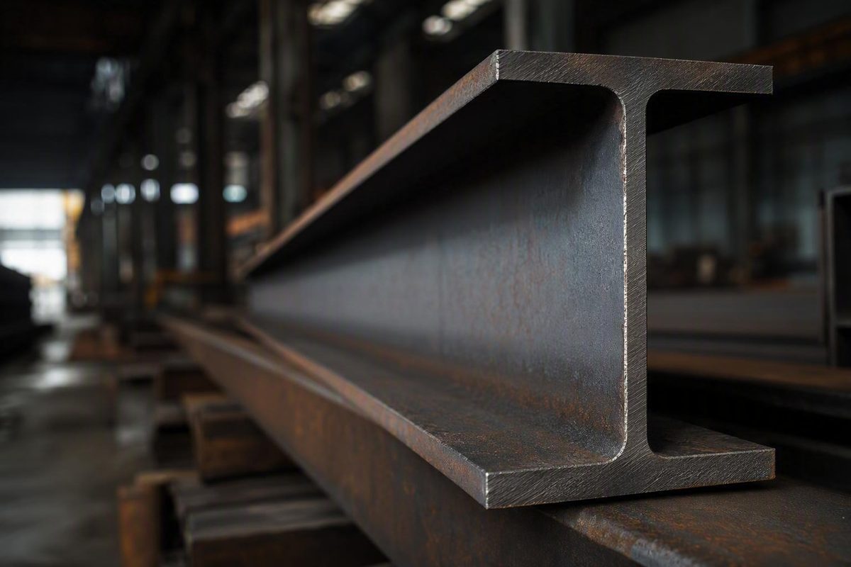
W18x35 dimensions at a glance
The W18×35 is a wide-flange steel shape with a tabulated overall depth of 17.70 inches, a flange width of 6.00 inches, a 0.300-inch web, 0.425-inch flanges, and a nominal weight of 35 pounds per foot. Its commonly listed metric designation is W460×52. The following values come from a third-party table attributed to AISC Shapes Database v16.0; they have not been independently verified here against the current official database. Optimal Beam publishes the corresponding W18×35 dimensions and properties.
| Property | Symbol | Imperial value | Rounded metric value |
|---|---|---|---|
| Overall depth | d | 17.70 in | approximately 450 mm |
| Flange width | b_f | 6.00 in | approximately 152 mm |
| Web thickness | t_w | 0.300 in | 7.62 mm |
| Flange thickness | t_f | 0.425 in | approximately 10.8 mm |
| Cross-sectional area | A | 10.30 in² | approximately 6,650 mm² |
| Nominal weight or mass per length | — | 35 lb/ft | approximately 52.0–52.1 kg/m |
| Common designation | — | W18×35 | W460×52 |
These are published tabulated values, not guaranteed measurements of every delivered member. The metric values are rounded conversions, not separate specifications with greater precision. Actual products remain subject to the governing manufacturing requirements and tolerances.
W18×35 cross-section — NOT TO SCALE
                    ←──────── bf = 6.00 in ────────→
                 ┌──────────────────────────────────┐
                 │                                  │  ↑
                 └──────────────┬──┬────────────────┘  │ tf = 0.425 in
                                │  │
                                │  │
                                │  │
                                │  │  tw = 0.300 in
                         d      │  │
                     17.70 in   │  │
                                │  │
                                │  │
                                │  │
                 ┌──────────────┴──┴────────────────┐  │ tf = 0.425 in
                 │                                  │  ↓
                 └──────────────────────────────────┘

                 NOT TO SCALE — SYMBOL REFERENCE ONLY
The four principal symbols are:
- d: overall section depth
- b_f: overall flange width
- t_w: web thickness
- t_f: flange thickness
This simplified drawing explains the symbols only. The rolled profile includes curved flange-to-web transitions and other dimensions that are not shown, so the diagram must not be scaled or used as a fabrication template.
What the W18x35 designation means
The designation W18×35 identifies a standardized shape; it does not reproduce the section’s exact dimensions.
- W identifies a wide-flange section composed of two flanges connected by a web.
- 18 identifies the nominal depth family, not an exact 18-inch measurement.
- 35 identifies the nominal weight in pounds per linear foot.
Consequently, a W18×35 is not exactly 18 inches deep. Its published overall depth is 17.7 inches. BG Structural Engineering likewise explains that the first number in a W-shape designation is nominal and that exact dimensions must be obtained from the applicable shape table. Its Steel Construction Manual guide discusses W-shape naming and tabulated dimensions.
The designation answers a limited but important question: which section is being referenced? It does not state:
- The ASTM material specification or steel grade
- Yield or tensile strength
- Guaranteed delivered dimensions
- Maximum span
- Allowable or design load
- Unbraced length or lateral-restraint conditions
- Connection capacity
- Deflection or vibration performance
- Compliance with a particular code or project specification
This distinction matters during coordination. Treating “W18” as an exact 18-inch dimension can create conflicts at ceiling pockets, façade interfaces, mechanical services, bearing elevations, connections, and architectural enclosures. Preliminary layouts should use the tabulated depth while recognizing that the bare-shape dimension is not, by itself, a minimum required clearance.
The same principle applies to the second number. Multiplying member length by 35 lb/ft provides a nominal bare-section weight. It does not provide the final shipping, lifting, or erection weight of a fabricated assembly.
Reading the cross-section dimensions
The principal dimensions describe the section’s outer envelope and the thicknesses of its flange and web elements.
Overall depth, d. This is the vertical distance from the outside face of one flange to the outside face of the other.
Flange width, b_f. This is the total width across a flange from one outside edge to the other.
Web thickness, t_w. This is the thickness of the central vertical web. It is not the clear distance between the inside faces of the flanges.
Flange thickness, t_f. This is the reported thickness of each flange.
For the W18×35, those dimensions are d=17.7 inches, b_f=6.00 inches, t_w=0.300 inch, and t_f=0.425 inch. Beam Dimensions also reports a 0.402-inch flange-to-web fillet radius, but that isolated value does not supply every fillet, workable-flat, cope, weld-access, or connection-clearance dimension required for detailing. See the Beam Dimensions profile and dimensional table.
The bare section therefore fits within an approximate 17.7-by-6.0-inch tabulated envelope, but it is not a solid rectangle. Its 10.3-square-inch steel area is distributed among the flanges, web, and curved transition regions. The envelope is useful for early spatial studies, but it must not be treated as a guaranteed minimum opening or clearance.
These dimensions affect several practical tasks:
- Fit-up: checking whether a member can enter an existing opening, pocket, frame, or equipment area
- Clearance coordination: locating ceilings, ducts, pipes, façade supports, and adjacent framing
- Connection planning: establishing preliminary room for plates, bolts, welds, stiffeners, and copes
- Penetration studies: identifying potential conflicts with flanges, connections, or critical web regions
- Fireproofing coordination: allowing for protective material outside the bare steel profile
- Architectural concealment: sizing wraps, soffits, chases, and finish transitions
- Handling and erection: understanding the physical cross-section independently of length and weight
The four principal dimensions are only a starting point for fabrication. Connection detailing may also require applicable k dimensions, workable flats, gage locations, edge distances, access requirements, and tolerances. Those values should come from controlled project references and approved fabrication documents.
Some third-party databases display zeroes for fields such as flange gage, web gage, or web depth. Those entries appear to be unavailable or unpopulated fields and should not be interpreted as physical zero dimensions.
W18x35 weight by beam length
For a straight, bare W18×35, nominal imperial weight is calculated as:
Nominal weight (lb) = length (ft) × 35 lb/ft
A supplier chart independently lists the W18×35 at 35 lb/ft, supporting the following straightforward estimates. See the wide-flange beam specification chart.
| Member length | Calculation | Approximate nominal bare-section weight |
|---|---|---|
| 10 ft | 10×35 | 350 lb |
| 20 ft | 20×35 | 700 lb |
| 30 ft | 30×35 | 1,050 lb |
For example:
20 ft × 35 lb/ft = 700 lb
The result should be stated as approximately 700 pounds, not as the guaranteed weight of a delivered or fabricated member.
In metric units:
Nominal mass (kg) = length (m) × approximately 52.0 to 52.1 kg/m
A 6 m bare section therefore has an estimated nominal mass of:
6 m × 52.0 kg/m ≈ 312 kg
The difference between 52.0 and 52.1 kg/m reflects rounding and display precision. Converting 35 lb/ft produces approximately 52.1 kg/m, while some tables display the value as 52.0 kg/m.
These calculations cover the nominal bare shape only. They exclude:
- End plates, base plates, shear tabs, and moment-connection plates
- Bolts, nuts, washers, and anchors
- Weld metal
- Stiffeners, doublers, bearing plates, and reinforcement
- Primer, galvanizing, and other coatings
- Fire-resistive material and enclosure systems
- Seats, clips, deck angles, and miscellaneous attachments
- Temporary erection hardware
- Packaging and lifting assemblies
Estimating, transport, rigging, and crane planning should use the weight of the complete fabricated assembly rather than the section’s 35 lb/ft designation alone.
The reported area also supplies a reasonableness check.
10.3 in² × 12 in/ft × 0.283 lb/in³ ≈ 35.0 lb/ft
This calculation can help detect a unit or transcription error, but the published nominal unit weight remains the primary reference.
Section properties and axis conventions
Dimensions describe the physical profile. Section properties describe how the cross-sectional area is distributed about defined axes. They are geometric inputs to engineering calculations, not allowable loads or standalone capacities.
Under common AISC notation:
- x-x is the major or strong axis, passing horizontally through the centroid.
- y-y is the minor or weak axis, passing vertically through the centroid.
The following properties are reported for the W18×35. CivilAxis publishes the same major- and minor-axis values but uses different axis letters, identifying its major axis as y-y and its minor axis as z-z. Review the CivilAxis W18×35 property table and axis convention.
| Property | Major or strong axis, x-x | Minor or weak axis, y-y |
|---|---|---|
| Moment of inertia | I_x=510 in^4 | I_y=15.3 in^4 |
| Elastic section modulus | S_x=57.6 in^3 | S_y=5.12 in^3 |
| Plastic section modulus | Z_x=66.5 in^3 | Z_y=8.06 in^3 |
| Radius of gyration | r_x=7.04 in | r_y=1.22 in |
Additional reported properties are:
| Property | Symbol | Published value |
|---|---|---|
| St. Venant torsional constant | J | approximately 0.51 in⁴ |
| Warping constant | C_w | 1,140 in⁶ |
In practical terms:
The flanges place substantial area far from the major-axis neutral axis, so major-axis bending stiffness is much greater than minor-axis bending stiffness.
Axis-label crosswalk
Axis letters are not universal across every reference.
| Axis meaning | Common AISC notation | Alternate notation used by some references | W18×35 moment of inertia |
|---|---|---|---|
| Major or strong axis | x-x | y-y | 510 in⁴ |
| Minor or weak axis | y-y | z-z | 15.3 in⁴ |
Never transfer a property based solely on an axis letter. First determine whether the source means the major or minor axis. Interchanging 510 in⁴ and 15.3 in⁴ would materially alter a stiffness, stress, or stability calculation.
These values are useful for reference and preliminary work when the data edition is understood. Final engineering should confirm them in the current official AISC Shapes Database or the project-approved Steel Construction Manual.
Shape dimensions, steel grade, and capacity are different questions
Avoiding misuse begins with separating four distinct categories of information.
1. Shape geometry
Geometry includes:
- Overall depth
- Flange width
- Web thickness
- Flange thickness
- Fillets and detailing dimensions
- Cross-sectional area
The W18×35 designation points to a defined geometric shape and nominal unit weight. It does not identify every material or product attribute.
2. Geometric section properties
These include I, S, Z, r, J, and C_w. They depend on the distribution of cross-sectional area and are used in many design calculations. They are not capacities by themselves.
3. Material properties
They include yield strength, tensile strength, ductility requirements, and other grade-dependent characteristics.
Engineering Database, for example, lists a specific A36 carbon-steel W18×35 with a yield strength of 36,000 psi. That strength applies to the listed A36 product and must not be generalized to every W18×35. See the grade-specific A36 listing.
Shape and material specification must therefore be verified separately.
4. Project-specific design capacity
Capacity depends on section geometry and material properties, but it also depends on how the member is loaded, supported, braced, connected, and evaluated.
The W18×35 designation and dimensional table cannot independently establish:
- Allowable or design load
- Maximum span
- Service-load deflection
- Flexural or shear strength
- Compression or tension strength
- Local or overall buckling resistance
- Lateral-torsional buckling resistance
- Vibration performance
- Bearing adequacy
- Connection capacity
- Fire-resistance performance
A project-specific evaluation normally requires:
- Confirmed material specification and steel grade
- Clear span and total member length
- Support and end conditions
- Load magnitudes, types, locations, and distribution
- Applicable dead, live, snow, wind, seismic, equipment, and construction loads
- Governing load combinations
- Unbraced length
- Compression-flange restraint and lateral bracing
- Deflection and vibration criteria
- Connection configuration and design
- Applicable code and specification editions
- Holes, copes, notches, reinforcement, damage, or section loss
- Exposure, durability, and fire-protection requirements
A result calculated for one assumed span, grade, loading pattern, restraint condition, and design standard is not a universal W18×35 rating. Selection and final verification should be performed or reviewed by a qualified structural professional.
Tolerances, material variants, and final verification
Published dimensions are tabulated shape dimensions. Actual rolled members are subject to manufacturing variation under the governing product standards and mill practices. BG Structural Engineering’s manual guide likewise notes unavoidable dimensional variation and directs users to the applicable shape tables and standard mill practices. Review its discussion of shape data and manufacturing variation.
No numerical rolling tolerances are stated here because the evidence supplied does not establish the current limits applicable to a particular product, order, or project.
The tabulated 17.70-by-6.00-inch dimensions can support preliminary studies of the bare section. They are not a minimum opening size and do not account for rolling variation, fillets, connections, coatings, fireproofing, erection tolerances, or field conditions.
Tolerance-sensitive situations include:
- Passing a member through an existing wall or equipment opening
- Fitting a flange between installed plates
- Fabricating a saddle or cover plate before the member arrives
- Concealing a beam in a shallow architectural pocket
- Routing equipment or services close to a flange
- Detailing retrofit work around an existing member
- Coordinating assemblies in which multiple tolerances accumulate
Depending on the project stage and risk, verification may involve:
- The current official AISC Shapes Database or applicable Steel Construction Manual
- The specified ASTM material and product standard
- Project specifications and approved structural drawings
- Supplier order acknowledgments and product data
- Mill records or material certifications
- Shop measurements of the delivered member
- Requests for information where field conditions conflict with design documents
Metric values require similar care. The exact conversion of 17.7 inches is approximately 449.6 mm, although a quick-reference table may show 450 mm. Six inches may be displayed as 152 or 152.4 mm, and nominal mass may appear as 52.0 or 52.1 kg/m. CivilAxis illustrates the more precise 449.6 mm, 152.4 mm, and 52.1 kg/m conversions. Compare its imperial and metric W18×35 values.
These differences reflect rounding, not distinct section sizes. For procurement and fit-up, use a controlled project reference and a consistent rounding policy rather than combining whichever converted values appear most precise across several tables.
Hot-rolled carbon steel versus stainless products
Stainless Structurals, for example, offers a laser-fused stainless W18×35 in 304/L and 316/L grades with matching principal dimension numbers. See the vendor’s stainless W18×35 listing.
A substitution should be reviewed against project specifications and engineering requirements rather than accepted solely because the shape designation matches.
What a diagram can—and cannot—do
A cross-section diagram is useful for explaining d, b_f, t_w, and t_f. It should not be used to:
- Scale dimensions
- Locate holes
- Establish fillet clearances
- Lay out weld access
- Set cope dimensions
- Determine gage lines
- Generate CNC geometry
- Replace approved fabrication documents
Fabrication should use controlled numerical data, applicable standards, and project-specific details.
Final verification checklist
Before using a W18×35 for design, detailing, procurement, fabrication, or erection planning, confirm:
- Shape designation: Is the required section actually W18×35?
- Table edition: Are dimensions and properties from the current project-approved reference?
- Steel grade: What ASTM specification and grade are required?
- Product type: Is the member hot-rolled carbon steel, laser-fused stainless, or another specified product?
- Tolerance requirements: Is fit-up sensitive to rolling, fabrication, or erection variation?
- Member length: Is the ordered, detailed, and estimated length correct?
- Fabrication additions: Are plates, bolts, welds, stiffeners, coatings, and fireproofing included in weight and clearance calculations?
- Documentation: Do supplier information, mill records, and shop drawings agree?
- Engineering review: Have loading, supports, bracing, deflection, connections, and governing requirements been evaluated for the actual project?
W18x35 FAQ
Is a W18x35 exactly 18 inches deep?
No. The “18” identifies the nominal depth family rather than an exact dimension. The published overall depth is 17.70 inches, approximately 449.6 mm and commonly rounded to 450 mm. Use the tabulated value—not the family name—for preliminary coordination. Optimal Beam lists the imperial depth and rounded metric value.
What are the flange and web thicknesses of a W18x35?
The published flange thickness, t_f, is 0.425 inch, or approximately 10.8 mm. The web thickness, t_w, is 0.300 inch, or 7.62 mm. Delivered products remain subject to applicable manufacturing tolerances. Beam Dimensions reports the corresponding imperial thicknesses.
How much does a 20-foot W18x35 beam weigh?
Using the nominal unit weight:
20 ft × 35 lb/ft = 700 lb
A bare 20-foot W18×35 therefore has a nominal weight of approximately 700 pounds. Connection material, reinforcement, coatings, fireproofing, and other additions increase the fabricated assembly weight.
What is the metric equivalent of W18x35?
The commonly listed metric designation is W460×52. Rounded dimensions are approximately 450 mm deep and 152 mm wide, with a 7.62 mm web, 10.8 mm flanges, and a nominal mass of approximately 52.0–52.1 kg/m.
How much load can a W18x35 support?
There is no universal load rating based on the shape designation alone. Capacity depends on material grade, span, support conditions, loading, unbraced length, lateral restraint, deflection criteria, connections, load combinations, and the governing design standard. A qualified structural professional should evaluate the actual project conditions; the shape name does not approve a design.
Final verification takeaway
The core reference is straightforward: a W18×35 is tabulated at 17.7 inches deep and 6.00 inches wide, with a 0.300-inch web, 0.425-inch flanges, and a nominal weight of 35 lb/ft. Those values are suitable for quick reference and preliminary coordination, but not as guaranteed delivered measurements or proof of capacity. Final design, detailing, procurement, and tolerance-sensitive fabrication should use current official AISC information, the specified steel grade, applicable standards, and supplier or mill documentation.