
Following the Load Path Through a Bolted Moment Connection
The legacy extract ends during flange-plate block shear, omitting its completed result and the final column-stiffening determination.
What This Connection Example Does—and Does Not—Establish
This AISC connection example is an annotated review of a legacy bolted flange-plate fully restrained moment connection. It follows beam-end shear and moment through the beam flanges and web, bolts, connection plates, welds, and supporting column. The published values are useful for understanding how a connection calculation is organized and how LRFD and ASD demands are kept separate.
It is not a complete, current, project-ready design. The underlying document is identified as AISC Design Examples v13.0, reflecting an older Manual and Specification context. The available copy also contains severe OCR and equation-formatting defects. Member sizes and many reported results are readable, but some bolt, hole, weld, and dimensional information cannot be recovered safely without intact original figures.
A separate 2021 SkyCiv interpretation examines substantially the same W18×50-to-W14×99 arrangement. It is vendor-authored instructional material rather than an official AISC publication. It also reports a different flange force and documents a discrepancy between the flange-plate width shown in its illustration and the width used in its calculations.
The evidence is incomplete in another important respect: the available legacy extract ends during the flange-plate block-shear calculation and does not include the completed block-shear result or final column-stiffening determination. The published numbers therefore support an annotated walkthrough of selected checks, not a conclusion that every applicable limit state passes.
That distinction follows the basic connection-design principle summarized for ANSI/AISC 360-22 Section J1: every applicable connection component must have available strength at least equal to required strength, and the connection must provide a continuous load path satisfying the applicable limit states. Those components include connecting elements, connectors, and affected elements of the connected members—not only the visible bolts (Modern Steel Construction, “Bolted Connection Design—A Primer”).
Educational-use notice
This walkthrough does not replace project-specific design, checking, detailing, or review by a qualified structural engineer. Before any part of the example is used on a project, confirm the governing building code, AISC Specification and Manual, applicable RCSC requirements, welding requirements, load combinations, materials, geometry, bolt and hole conditions, resistance or safety factors, and every applicable limit state.
Because the publisher’s available first-party material does not establish structural connection-design credentials, publication of this high-stakes technical content should be conditioned on review by a named PE or SE experienced in steel connections. The review record should identify the reviewer, credentials, date, scope, and code editions checked.
The example should be read as a calculation framework:
- Define the connection and verify its geometry.
- Establish LRFD and ASD demands.
- Trace the separate moment and shear load paths.
- Resolve moment into flange force using a verified lever arm.
- Check the affected beam elements.
- Check bolts, plates, holes, and welds.
- Check affected column elements.
- Resolve every missing, conflicting, or dimension-dependent result.
- Obtain independent checking and qualified engineering review.
All equations, factors, dimensions, hole requirements, and detailing provisions must be checked against the editions governing the actual work. A result developed under one edition or assumed geometry does not automatically remain valid after the standards, loads, dimensions, materials, or connection configuration change.
Connection Layout, Loads, Materials, and Fasteners
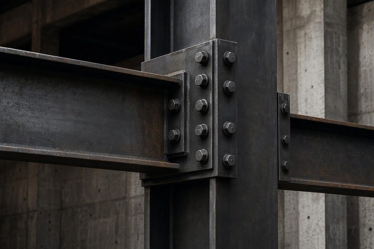
The example connects a W18×50 beam to the flange of a W14×99 column. Top and bottom bolted flange plates transfer moment, while a single-plate web connection transfers beam shear.
The arrangement comprises two related load paths:
- Moment path: beam flange → flange bolts → flange plate → plate-to-column weld → column flange and web.
- Shear path: beam web → web bolts → single web plate → plate-to-support weld → column.
The readable legacy data identify ASTM A992 beam and column shapes, ASTM A36 connection plates, a PL 3/8×4×0’-9 web-plate trial, and a PL 3/4×7 flange-plate trial. The following inputs and reported legacy properties must be checked against intact original figures before being used for calculation or fabrication (hosted AISC Design Examples v13.0 extract).
| Input category | Reported example value |
|---|---|
| Beam | W18×50 |
| Supporting column | W14×99 |
| Beam dead-load shear, R_D | 7 kip |
| Beam live-load shear, R_L | 21 kip |
| Dead-load moment, M_D | 42 kip-ft |
| Live-load moment, M_L | 126 kip-ft |
| Beam and column material | ASTM A992 |
| W-shape yield strength, F_y | 50 ksi |
| W-shape tensile strength, F_u | 65 ksi |
| Plate material | ASTM A36 |
| Plate yield strength, F_y | 36 ksi |
| Plate tensile strength, F_u | 58 ksi |
| Legacy web-plate trial | PL 3/8×4×0’-9 |
| Legacy flange-plate trial | PL 3/4×7 |
The SkyCiv interpretation identifies eight 7/8-in ASTM A325-N bolts in the flange connection and three 7/8-in ASTM A325-N bolts at the web plate. Its illustration shows a 7.0-in-wide flange plate, while its calculations reportedly use 7.5 in; SkyCiv flags that difference as an erratum affecting the results (SkyCiv’s 2021 moment-connection example).
A current project must establish the applicable bolt specification and designation, strength group, installation condition, hole type, number of shear planes, and whether threads are included in or excluded from the relevant shear planes.
Recommended connection illustration
A useful calculation-package illustration should label:
- W18×50 beam;
- W14×99 column;
- top and bottom flange plates;
- single web plate;
- flange-bolt rows;
- web-bolt row;
- flange-plate weld lines;
- web-plate weld line;
- beam-end shear;
- tension and compression flange forces forming the moment couple; and
- continuation of force into the column flange and web.
It should not add dimensions that have not been verified from an intact drawing. A conceptual load-path diagram can avoid an unsupported numerical lever arm:
                    COLUMN
                 flange / web
                      │
       weld  ◄────────┼────────►  weld
                      │
   top flange plate ══╪════════
         flange bolts ● ● ● ●
BEAM  ═════════════════════════════
           moment couple:  T ↔ C
           web bolts:      ●
                           ●  → beam shear
                           ●
              web plate ───┼── weld
                           │
   bottom flange plate ════╪════
         flange bolts ● ● ● ●
                      │
The diagram shows which components transfer load. It is not a fabrication detail and supplies none of the dimensions required to calculate strength.
Step 1: Calculate ASD and LRFD Connection Demands
The connection geometry does not change between ASD and LRFD. What changes is the required-strength calculation and the format in which demand is compared with available strength.
For the legacy ASD case, the stated dead and live service-load effects are added directly. For the legacy LRFD case, the example applies 1.2D+1.6L. These are source-reported example combinations, not universal project combinations.
| ASD demand | LRFD demand |
|---|---|
| R_a=7 kip+21 kip | R_u=1.2(7 kip)+1.6(21 kip) |
| R_a=28 kip | R_u=42 kip |
| M_a=42 kip-ft+126 kip-ft | M_u=1.2(42 kip-ft)+1.6(126 kip-ft) |
| M_a=168 kip-ft | M_u=252 kip-ft |
The arithmetic is:
R_u = 1.2(7) + 1.6(21) = 8.4 + 33.6 = 42 kip
M_u = 1.2(42) + 1.6(126) = 50.4 + 201.6 = 252 kip-ft
R_a = 7 + 21 = 28 kip
M_a = 42 + 126 = 168 kip-ft
These load inputs and resulting demands reproduce the reported legacy example values (AISC Design Examples v13.0, Example II.B-1).
Unit check
A kip is a force. A kip-ft is a moment. A 168-kip-ft moment cannot be compared directly with a bolt, plate, or weld capacity stated in kips. The moment must first be converted into a compatible force through a justified mechanical model, such as a tension-compression couple with a verified lever arm.
| Method | Required shear | Required moment | Basis |
|---|---|---|---|
| ASD | 28 kip | 168 kip-ft | Dead plus live service effects |
| LRFD | 42 kip | 252 kip-ft | Legacy 1.2D+1.6L calculation |
These combinations should not be generalized as governing every building or connection. A project design must identify all applicable combinations and effects, including any required wind, seismic, construction, erection, stability, transfer, or reversal cases. The combination controlling shear need not control moment.
Design formats must also remain separate:
- LRFD required strength is compared with LRFD design strength.
- ASD required strength is compared with ASD allowable strength.
Comparing the 252-kip-ft LRFD demand with a capacity reported only in ASD format would be invalid unless the capacity were recalculated in the corresponding format.
Step 2: Trace the Load Path and Resolve Moment Into Flange Force
The beam end delivers shear and moment to the same joint, but the flange plates and web plate provide distinguishable load paths.
For moment:
- One beam flange develops tension while the other develops compression.
- The flange forces enter the bolts connecting each beam flange to its flange plate.
- The flange plates carry the forces to their welds at the column.
- The welds transfer the forces into the column flange.
- The column flange and web distribute them into the supporting member and surrounding frame.
For shear:
- Beam shear acts through the beam web.
- The web bolts transfer it to the single plate.
- The plate carries it to its weld.
- The weld transfers it into the column.
Conceptually, the beam-end moment is resisted by a couple:
F_f ≈ M ÷ z
where:
- F_f is the flange-force magnitude;
- M is the applicable beam-end moment; and
- z is the lever arm between the resultants forming the couple.
The equation is simple; selecting z is not. The lever arm must correspond to the assumed locations of the tension and compression resultants. Depending on the analytical model, those locations might relate to flange centroids, plate force lines, or another justified geometry. The model must agree with the detailed connection and the calculation from which downstream capacities are taken.
The available sources report several force values that cannot be treated as interchangeable:
| Reported force or demand | Source and calculation stage | Required treatment |
|---|---|---|
| 107.5 kip | SkyCiv ASD flange force | Pair only with SkyCiv capacities based on that model |
| 112 kip | Legacy ASD initial flange-bolt force | Pair only with the corresponding legacy bolt calculation |
| 168 kip | Legacy LRFD initial flange-bolt force | Pair only with the corresponding legacy bolt calculation |
| 108 kip | Legacy ASD flange-plate demand | Pair only with the reported legacy plate checks |
| 161 kip | Legacy LRFD flange-plate demand | Pair only with the reported legacy plate checks |
The 108-kip and 161-kip plate demands introduce an additional consistency problem. The accessible extract reports them for the plate yielding and rupture comparisons, but the available OCR text does not preserve enough intact equations and geometry to show why they differ from the 112-kip and 168-kip initial bolt-design forces. They may reflect a different calculation stage, adjustment, or assumption, but that cannot be established from the supplied evidence.
Accordingly, the bolt and plate values cannot yet be presented as one internally reconciled design sequence. Each reported demand must stay paired with its own source calculation until the intact equations and geometry are recovered.
A reviewer should:
- retrieve the intact source pages and figures;
- identify the lever arm used for each force;
- identify any adjustment between initial bolt force and plate demand;
- verify whether the LRFD and ASD values use equivalent assumptions;
- reproduce the arithmetic from confirmed geometry; and
- carry one consistent force model through bolts, plates, welds, and column checks.
A flange-force result cannot safely be reused after changing:
- beam depth or flange thickness;
- plate position, width, or thickness;
- distance between flange-force resultants;
- bolt-row arrangement;
- weld location;
- beam-end moment;
- connection eccentricity;
- column orientation; or
- assumptions about which components participate in moment transfer.
For a given moment, a smaller lever arm produces a larger flange force, while a larger lever arm produces a smaller force. That force directly affects bolts, plates, welds, and column-local checks, making the moment-to-force conversion a central design assumption rather than a preliminary bookkeeping step.
Step 3: Check the Beam Flange and Web Connection
Connection elements cannot develop a reliable load path if the affected beam elements are inadequate at bolt holes or other reduced sections. The legacy procedure therefore begins with the beam’s available flexural strength at the flange holes.
The legacy source reports:
| Beam check | Required moment | Reported available strength | Utilization |
|---|---|---|---|
| LRFD flexure at flange holes | 252 kip-ft | 318 kip-ft | 252/318=0.792 |
| ASD flexure at flange holes | 168 kip-ft | 211 kip-ft | 168/211=0.796 |
These are source-reported available strengths and article-calculated utilization ratios. Both displayed ratios are below 1.0, but that observation applies only to this selected legacy beam-flexure comparison. It does not establish complete beam or connection adequacy.
Web-plate trial
The readable legacy designation is:
PL 3/8 × 4 × 0’-9
This denotes a nominal trial plate 3/8 in thick, 4 in wide, and 9 in long. The example reports three bolts and fillet welds. Bolt positioning, weld size, hole dimensions, clear distances, and edge distances remain subject to verification against the intact original drawing.
The source-reported web-plate strengths are:
| Web-plate limit state | LRFD available strength | LRFD demand | ASD available strength | ASD demand |
|---|---|---|---|---|
| Shear yielding | 72.9 kip | 42 kip | 48.6 kip | 28 kip |
| Shear rupture | 58.7 kip | 42 kip | 39.2 kip | 28 kip |
The corresponding arithmetic is:
Shear yielding, LRFD = 42 ÷ 72.9 = 0.576
Shear yielding, ASD = 28 ÷ 48.6 = 0.576
Shear rupture, LRFD = 42 ÷ 58.7 = 0.716
Shear rupture, ASD = 28 ÷ 39.2 = 0.714
Among these selected comparisons, shear rupture is more highly utilized than shear yielding. All four displayed ratios are below 1.0, but they represent only the source-reported yielding and rupture checks—not a complete web-connection verification.
Web-connection checklist
A complete review should address, where applicable:
- bolt shear;
- bolt tension or combined shear and tension;
- slip resistance when required;
- bearing at each bolt hole;
- tearout at edge holes and between holes;
- web-plate shear yielding;
- web-plate shear rupture;
- web-plate block shear;
- plate flexure or other eccentricity effects;
- weld strength;
- base-metal strength adjacent to the weld;
- beam-web bearing, tearout, rupture, and block shear;
- supporting-member local effects;
- bolt spacing and edge-distance requirements;
- hole type and dimensions;
- installation condition;
- fit-up, erection, and access; and
- any ductility or rotation assumptions associated with the connection model.
Hole geometry is a strength input, not merely a drafting concern. Hole diameter, clear distance, edge distance, bolt spacing, plate thickness, and force direction can change bearing, tearout, net-section, and block-shear resistance. Thread position relative to a shear plane can also affect bolt resistance under applicable provisions.
No OCR-corrupted hole size or minimum spacing from the extract should be repeated as a current requirement. Those values must be established from the governing AISC and RCSC documents and coordinated with the selected hole type, installation condition, and connected-part geometry.
Equal force per bolt is appropriate only when supported by the loading and bolt-group model. If the web-bolt group is eccentric relative to the transferred shear, the designer must use a justified group-analysis method and apply consistent assumptions to bolt shear, bearing, and tearout.
Step 4: Size the Flange Bolts and Check the Flange Plates
The legacy example reports that bolt shear controls its initial flange-bolt calculation. It gives a requirement of 7.78 bolts and selects eight:
n_reported required = 7.78
n_provided = 8
The second step is simple rounding because a fraction of a bolt cannot be provided. The first step—the derivation of 7.78—is not reproducible from the supplied OCR extract with sufficient confidence.
The available evidence does not preserve a reliable combination of:
- source-era bolt resistance;
- bolt cross-sectional area used;
- number of shear planes;
- thread condition;
- resistance or safety factor;
- hole and connection condition; and
- exact force divided by per-bolt resistance.
The 7.78 value must therefore be described as a reported result, not as a demonstrated calculation. It should not be represented as independently reproduced until the intact source equation and inputs are recovered.
The reported selection is specific to the example’s loads, materials, bolt properties, shear-plane assumptions, hole conditions, and geometry. Changing any of those inputs may change the required quantity or arrangement.
Flange-plate tension checks
The legacy plate trial is reported as PL 3/4×7. The documented checks include:
- gross-section tension yielding;
- net-section tension rupture; and
- two potential block-shear paths.
The source reports the following plate comparisons:
| Limit state | Method | Reported demand | Reported available strength | Utilization |
|---|---|---|---|---|
| Gross-section tension yielding | LRFD | 161 kip | 170 kip | 161/170=0.947 |
| Gross-section tension yielding | ASD | 108 kip | 113 kip | 108/113=0.956 |
| Net-section tension rupture | LRFD | 161 kip | 163 kip | 161/163=0.988 |
| Net-section tension rupture | ASD | 108 kip | 109 kip | 108/109=0.991 |
These are legacy source-reported demands and capacities, with utilization calculated from the displayed values. They must not be silently substituted for the separate 168-kip LRFD and 112-kip ASD forces reported for the initial bolt calculation.
The rupture comparisons are especially close to 1.0. Verification of plate width, thickness, material properties, hole deductions, net-area assumptions, and resistance or safety factors is therefore essential. A small change in an input or interpretation could materially alter the comparison.
The source identifies two flange-plate block-shear paths and states that the outside-block tearout path is more critical. The supplied extract ends during that calculation, so no completed available strength or final comparison is available. Flange-plate block shear must remain unresolved.
Why the plate-width discrepancy matters
The reported 7.0-in-versus-7.5-in plate-width discrepancy can affect:
- gross area;
- net area;
- gross-section yielding strength;
- net-section rupture strength;
- length and position of potential failure paths;
- edge and clear distances;
- block-shear geometry;
- bolt placement feasibility; and
- resulting available strength.
For unchanged thickness, a narrower plate has less gross area. Net-section rupture also depends on verified hole deductions and the governing failure plane. Block shear depends on the specific tension and shear paths around the bolt group.
The available evidence does not support reliable recalculation at both widths. The correct response is to confirm the intended width and rerun every width-dependent check—not to assume that the published capacities apply to both dimensions.
Flange-bolt and plate verification
Before accepting the reported eight-bolt selection or plate comparisons, confirm:
- current bolt designation and properties;
- bolt diameter;
- threads included in or excluded from each shear plane;
- number of shear planes;
- bearing-type or slip-critical behavior;
- required installation condition;
- standard, oversized, short-slotted, or long-slotted holes;
- plate width, length, and thickness;
- bolt gage, pitch, spacing, and edge distances;
- beam-flange hole geometry;
- plate gross and net areas;
- every potential block-shear path;
- any bolt-group eccentricity;
- applicable resistance and safety factors; and
- agreement among the drawing, calculation model, and fabricated detail.
Step 5: Check Welds and Column-Local Limit States
Adequate flange bolts and plates do not complete the moment path. Flange force must still pass through the plate-to-column welds and into the column. The column flange and web must resist the resulting local effects.
Using its stated ASD flange force of 107.5 kip, the SkyCiv article reports the following selected ASD capacities (SkyCiv moment-connection example):
| Component or limit state | SkyCiv ASD demand | Reported ASD capacity | Demand/capacity |
|---|---|---|---|
| Flange-plate weld | 107.5 kip | 116.9 kip | 0.920 |
| Column web local yielding | 107.5 kip | 123.7 kip | 0.869 |
| Column flange local bending | 107.5 kip | 113.8 kip | 0.944 |
| Column web local crippling | 107.5 kip | 154.8 kip | 0.694 |
| Column web compression buckling | 107.5 kip | 139.0 kip | 0.773 |
Qualification: These ratios reproduce selected source-displayed comparisons. They are not a conclusion that the connection or supporting column is adequate.
The capacities must remain paired with SkyCiv’s 107.5-kip demand. They cannot be compared directly with the legacy 108-kip, 112-kip, 161-kip, or 168-kip values without recalculating the capacities under one consistent geometry and force model.
The largest correctly paired displayed ratio is for column flange local bending:
107.5 kip ÷ 113.8 kip = 0.944
The displayed weld ratio is:
107.5 kip ÷ 116.9 kip = 0.920
These ratios leave relatively limited margin within the source’s own displayed comparisons, increasing the importance of confirming the flange force, dimensions, material properties, factors, and applicable equations.
The SkyCiv web-compression-buckling presentation also contains an apparent denominator error. It lists a capacity of 139.0 kip but displays a ratio expression using 113.8 kip. The ratio associated with the reported 139.0-kip capacity is:
107.5 kip ÷ 139.0 kip ≈ 0.773
The 113.8-kip value belongs to the reported column-flange-local-bending check. The compression-buckling ratio should therefore be reconstructed from the correctly paired 107.5-kip demand and 139.0-kip capacity.
What remains beyond the displayed column checks
A complete supporting-member review may need to determine whether continuity plates, transverse stiffeners, doubler plates, or other reinforcement are required. That determination cannot be made from a short list of selected ratios below 1.0.
The review should establish, as applicable:
- effects of the tension flange force;
- effects of the compression flange force;
- column-flange local behavior;
- column-web yielding, crippling, buckling, and panel-zone behavior;
- interaction with column axial force and moment;
- force transfer through the opposite side of the column;
- behavior when beams frame from one side or both sides;
- load reversal;
- continuity-plate or stiffener strength and attachment;
- doubler-plate requirements and force transfer;
- weld access and constructability; and
- compatibility with the frame-analysis assumptions.
The supplied evidence does not complete that work. The displayed SkyCiv ratios establish only what the vendor article reports for selected checks under its 107.5-kip ASD demand. They do not prove that column reinforcement is unnecessary.
Results Matrix, Missing Checks, and Independent Verification
The matrix below deliberately separates the legacy-source model from the SkyCiv model. Values from the two models must not be combined into one design sequence unless their geometry, loads, force conversion, factors, and governing assumptions are first reconciled.
“Below 1.0” describes only the arithmetic comparison displayed by the relevant source. It is not a final engineering pass/fail conclusion.
| Source/model | Component | Limit state | Method | Required strength | Reported available strength | Utilization | Displayed status | Verification note |
|---|---|---|---|---|---|---|---|---|
| Legacy | Beam at flange holes | Flexure | LRFD | 252 kip-ft | 318 kip-ft | 0.792 | Below 1.0 | Confirm holes, section properties, factors, and current provisions |
| Legacy | Beam at flange holes | Flexure | ASD | 168 kip-ft | 211 kip-ft | 0.796 | Below 1.0 | Same verification required |
| Legacy | Web plate | Shear yielding | LRFD | 42 kip | 72.9 kip | 0.576 | Below 1.0 | Confirm plate geometry and material |
| Legacy | Web plate | Shear yielding | ASD | 28 kip | 48.6 kip | 0.576 | Below 1.0 | Confirm plate geometry and material |
| Legacy | Web plate | Shear rupture | LRFD | 42 kip | 58.7 kip | 0.716 | Below 1.0 | Confirm net area and holes |
| Legacy | Web plate | Shear rupture | ASD | 28 kip | 39.2 kip | 0.714 | Below 1.0 | Confirm net area and holes |
| Legacy | Flange bolts | Bolt shear/count | Initial calculation | 7.78 bolts required | 8 selected | — | Reported selection | Per-bolt derivation is not reproducible from supplied OCR |
| Legacy | Flange plate | Gross-section yielding | LRFD | 161 kip | 170 kip | 0.947 | Below 1.0 | Demand differs from initial 168-kip bolt force |
| Legacy | Flange plate | Gross-section yielding | ASD | 108 kip | 113 kip | 0.956 | Below 1.0 | Demand differs from initial 112-kip bolt force |
| Legacy | Flange plate | Net-section rupture | LRFD | 161 kip | 163 kip | 0.988 | Below 1.0 | Confirm width, holes, net area, and factors |
| Legacy | Flange plate | Net-section rupture | ASD | 108 kip | 109 kip | 0.991 | Below 1.0 | Confirm width, holes, net area, and factors |
| Legacy | Flange plate | Block shear | LRFD/ASD | Path under evaluation | Incomplete | — | Unresolved | Outside-block path reportedly critical; extract ends mid-check |
| SkyCiv | Flange-plate weld | Weld strength | ASD | 107.5 kip | 116.9 kip | 0.920 | Below 1.0 | Confirm weld geometry, electrode, effective length, and base metal |
| SkyCiv | Column web | Local yielding | ASD | 107.5 kip | 123.7 kip | 0.869 | Below 1.0 | Selected displayed check only |
| SkyCiv | Column flange | Local bending | ASD | 107.5 kip | 113.8 kip | 0.944 | Below 1.0 | Largest correctly paired displayed SkyCiv ratio |
| SkyCiv | Column web | Local crippling | ASD | 107.5 kip | 154.8 kip | 0.694 | Below 1.0 | Selected displayed check only |
| SkyCiv | Column web | Compression buckling | ASD | 107.5 kip | 139.0 kip | 0.773 | Below 1.0 | Source denominator presentation error corrected arithmetically |
| Project-specific | Column reinforcement | Stiffeners, continuity plates, doubler plates, and attachments | Governing project method | Not established | Not established | — | Unresolved | Final determination absent from supplied evidence |
What the matrix establishes
The published values illustrate a recognizable calculation sequence:
- beam-end shear and moment are calculated;
- moment is translated into a flange-force model;
- bolt shear reportedly controls the initial flange-bolt count;
- a reported requirement of 7.78 bolts is rounded up to eight;
- selected beam, web-plate, flange-plate, weld, and column-local comparisons are shown below 1.0.
That sequence is educationally useful. It demonstrates why connection design extends beyond a bolt count.
What the matrix does not establish
The matrix does not prove that the complete connection is adequate. In particular:
- flange-plate block shear is incomplete;
- the 7.0-in-versus-7.5-in plate-width discrepancy remains unresolved;
- important geometry and equations are OCR-corrupted;
- the 107.5-kip, 108-kip, 112-kip, 161-kip, and 168-kip force or demand values are not fully reconciled;
- the derivation of 7.78 required bolts cannot be reproduced from the available extract;
- current-edition factors and provisions have not been substituted;
- complete bearing, tearout, spacing, and hole checks are not demonstrated;
- all affected beam and column limit states are not documented;
- stiffener, continuity-plate, and doubler-plate requirements remain unknown; and
- project-specific load combinations and detailing have not been established.
A connection can be declared adequate only after every applicable component and limit state along the continuous load path has been evaluated using one consistent set of loads, geometry, materials, analytical assumptions, and governing provisions.
Pre-use verification checklist
Before using this framework for design or review:
- [ ] Identify the governing building code, AISC Specification, AISC Manual, RCSC specification, welding code, and project criteria.
- [ ] Retrieve intact original pages and figures rather than relying on OCR-extracted dimensions.
- [ ] Confirm beam and column sizes, orientation, material grades, and section properties.
- [ ] Confirm every plate width, length, thickness, and location.
- [ ] Resolve the 7.0-in-versus-7.5-in flange-plate discrepancy.
- [ ] Confirm bolt diameter, designation, strength, installation condition, hole type, and thread location.
- [ ] Confirm bolt gage, pitch, spacing, edge distance, and clear distance.
- [ ] Recalculate LRFD and ASD demands using the applicable project combinations.
- [ ] Reproduce the moment-to-flange-force calculation from verified geometry.
- [ ] Explain and reconcile the differing bolt and plate force values.
- [ ] Keep all demands and capacities in the same design format.
- [ ] Reproduce bolt shear, bearing, tearout, net-section, and block-shear calculations.
- [ ] Verify weld size, effective length, electrode strength, base metal, and load direction.
- [ ] Complete every applicable affected-beam and affected-column check.
- [ ] Determine whether continuity plates, stiffeners, doubler plates, or other reinforcement are required.
- [ ] Coordinate the calculation assumptions with the final shop-detail geometry.
- [ ] Obtain independent checking and qualified engineering review.
Using spreadsheets and connection-design software
Spreadsheets and software can automate repeated arithmetic, improve documentation, and make sensitivity studies practical. They can also preserve superseded factors, conceal geometry assumptions, mix units, or omit relevant limit states.
The SteelTools repository, for example, lists tools for flange-plate moment connections, shear tabs, clip angles, shear end plates, and bolt groups. Its listings span multiple AISC editions and design formats, including older ASD and LRFD resources; appearance in the directory does not establish independent validation or current-code compliance (SteelTools bolted-connection listings).
A sound verification process should compare software output with an independent calculation baseline. At minimum, compare:
- applied loads and combinations;
- force distribution;
- moment lever arm;
- connection eccentricity;
- bolt-group model;
- hole and edge geometry;
- plate gross and net areas;
- block-shear paths;
- effective weld lengths;
- resistance and safety factors;
- supporting-member assumptions; and
- the complete list of evaluated limit states.
Differences should be investigated rather than averaged. A vendor-hosted verification study of single-plate shear connections found that results depended on eccentricity assumptions, bolt-group treatment, tearout modeling, and localized plate behavior. The study involved particular shear-plate configurations, older cited standards, and vendor software, so its results cannot be generalized to this flange-plate moment connection. It nevertheless illustrates why two methods described as AISC-based can produce different answers (IDEA StatiCa single-plate verification example).
The central lesson is the load path. Beam shear travels through the web connection, while beam moment becomes a flange couple carried through bolts, plates, welds, and the column. The legacy example’s reported eight-bolt selection and selected below-capacity comparisons show how those checks can be organized. They do not resolve the incomplete block-shear calculation, dimensional discrepancy, conflicting force values, current-code requirements, or final column-reinforcement determination.
Use this annotated example as a review framework—not as a reusable detail. Project application requires recovered geometry, governing standards, consistently reproduced calculations, completed limit states, independent checking, and qualified structural-engineering review.
Frequently Asked Questions
Is this an official current AISC connection design example?
No. The underlying material is identified as AISC Design Examples v13.0 and reflects an older Manual and Specification context. The accessible copy is hosted on a university domain and contains OCR corruption. The 2021 SkyCiv article is a third-party vendor interpretation, not an official current AISC publication.
The example remains useful for understanding calculation sequence and load path, but it does not demonstrate compliance with current AISC, RCSC, or project requirements.
Why are eight flange bolts selected in the legacy example?
The legacy source reports that bolt shear controls the initial flange-bolt calculation. It reports a requirement of 7.78 bolts, which is rounded up to eight whole bolts.
The available extract does not preserve enough reliable information to reproduce the per-bolt resistance and the division that produced 7.78. The result should therefore be treated as source-reported rather than independently demonstrated.
Eight bolts are not a default requirement. The required number depends on the verified force, bolt properties, shear planes, thread condition, holes, materials, eccentricity, factors, and geometry.
Which limit states should be checked in a bolted flange-plate moment connection?
The final list depends on the connection geometry and governing provisions, but it commonly extends to:
- beam strength at flange and web holes;
- bolt shear and any applicable tension or combined loading;
- slip resistance when required;
- bearing and tearout at connected parts;
- gross-section yielding;
- net-section rupture;
- block shear;
- flange- and web-plate strength;
- weld and adjacent base-metal strength;
- eccentric bolt- and weld-group effects;
- column-flange local bending;
- column-web local yielding, crippling, buckling, and other applicable behavior;
- panel-zone and frame-interaction effects where applicable; and
- continuity plates, stiffeners, doubler plates, and their attachments.
The applicable checks must be derived from the actual continuous load path rather than accepted from a generic checklist alone.
Does the published example prove that column stiffeners or doubler plates are unnecessary?
No. The SkyCiv article displays several selected column-local ASD capacities above its stated 107.5-kip demand, but the legacy extract does not contain a complete final column-stiffening determination.
Ratios below 1.0 for selected checks do not establish that continuity plates, transverse stiffeners, doubler plates, or other reinforcement are unnecessary. That conclusion requires all applicable column and force-transfer checks under verified project conditions.
Can connection-design software or a spreadsheet replace the hand checks?
No. Software and spreadsheets can support calculation, documentation, iteration, and error checking, but they do not remove the engineer’s responsibility to verify inputs, units, geometry, code edition, assumptions, force distribution, and limit-state coverage.
A practical workflow is to establish an independent calculation baseline, compare it with the software result, and investigate differences. Particular attention should be paid to eccentricity, bolt-group analysis, hole conditions, plate failure paths, weld lengths, and supporting-member behavior. A workbook or program that cites AISC is not necessarily current, complete, independently validated, or appropriate for the connection under review.