
Choosing a Floor System by Span, Depth, Services, and Total Cost
Joists split into solid-sawn and I-joist systems. Truss webs create useful service zones, but their openings and obstructions are fixed once fabricated.
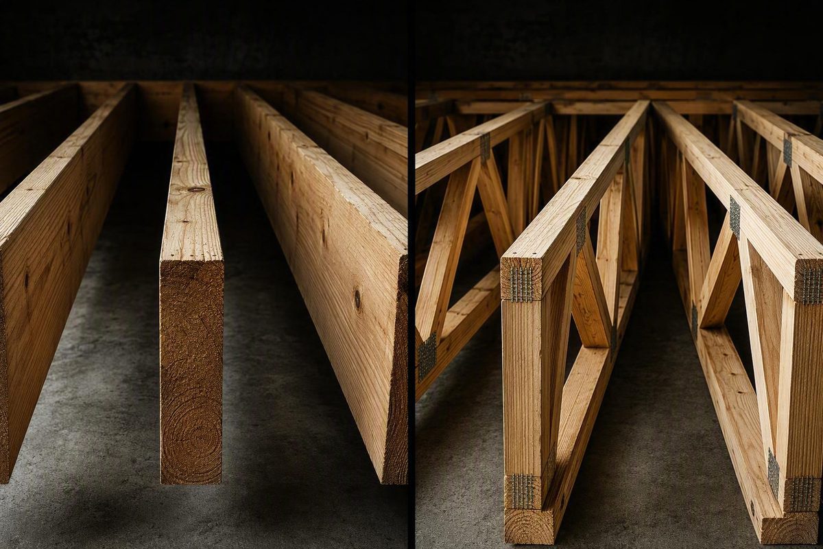
The familiar question—floor trusses vs floor joists—usually hides three materially different choices. A project may use solid-sawn dimensional-lumber joists, engineered wood I-joists, or prefabricated open-web wood floor trusses. Combining the first two under “joists” obscures important differences in span capability, structural depth, service penetrations, procurement, installation, and field modification.
There is no universal winner. Solid-sawn joists often make sense for short, straightforward floors. I-joists can offer consistent dimensions, relatively light handling, long stock lengths, and a comparatively shallow engineered system. Open-web floor trusses can be valuable where long clear spans or dense mechanical, electrical, plumbing, and sprinkler services drive the design.
The defensible choice comes from comparing all three systems against the same loads, supports, stiffness target, service layout, architectural dimensions, delivery assumptions, and scope—not from comparing isolated member prices or unmatched span claims.
First, clarify what “floor joists” means
A floor truss is a prefabricated assembly with top and bottom chords connected by triangulated open webs. Wood components are commonly joined at panel points with metal connector plates. Unlike an individual joist, the entire assembly works as a designed structural unit.
A solid-sawn floor joist is an individual dimensional-lumber member—such as a nominal 2×10 or 2×12—installed parallel to neighboring joists. Its capacity depends on lumber species, grade, actual dimensions, spacing, span, loading, bearing, and the applicable design rules.
An engineered I-joist is also an individual parallel member, but it has top and bottom flanges connected by a thinner structural web. The web is solid rather than naturally open like a floor truss. I-joists are manufactured products with series-specific capacities and installation requirements. These basic distinctions are summarized in a three-way comparison of floor trusses, solid-sawn joists, and I-joists, although final selection still requires project-specific documentation.
Solid-sawn joists and I-joists should not be treated as interchangeable. They differ in:
- available lengths and depths;
- dimensional consistency;
- permissible spans and spacing;
- hole, notch, and trimming rules;
- required blocking, rim, and connection details;
- field adaptability;
- manufacturer-supported design tools and literature; and
- the documentation used to select and approve the system.
As a starting orientation:
- Solid-sawn joists commonly suit simple, relatively short spans where suitable lumber is readily available.
- I-joists can provide greater consistency and practical span capability than traditional solid-sawn members while remaining relatively light.
- Open-web floor trusses are commonly considered where longer clear spans, custom geometry, or extensive service routing are priorities.
These are screening observations, not sizing rules. A deep, closely spaced I-joist may outperform a shallower truss under a particular set of conditions. A conventional joist floor divided by a well-placed beam may be more practical than either. Conversely, a truss may remove supports that would otherwise disrupt the plan.
All three systems perform the same fundamental job: transferring floor loads to bearings. Those bearings must carry the resulting reactions through walls, beams, posts, columns, or foundations. A floor member does not become an isolated structure merely because it spans a long distance; it remains one part of a continuous load path.
Floor trusses, solid-sawn joists, and I-joists at a glance
| Decision factor | Solid-sawn joists | Engineered I-joists | Open-web wood floor trusses |
|---|---|---|---|
| Structural form | Individual rectangular lumber members | Individual I-shaped members with flanges and a solid structural web | Prefabricated top and bottom chords connected by triangulated webs |
| Typical procurement | Stock lumber selected and cut for the floor layout | Stock or ordered engineered members selected from product data | Custom, project-specific package fabricated from an approved layout |
| General span suitability | Often efficient for shorter, repetitive spans | Can extend beyond practical solid-sawn layouts, depending on product series and depth | Common candidate for long clear spans and open plans |
| Floor depth | Determined by lumber size and support layout | Often comparatively shallow for an engineered system | May be deeper, particularly when used for long spans or large service zones |
| Handling | Familiar individual pieces; weight varies with size and moisture | Generally light and available in long lengths | Size and weight vary; long assemblies may need additional labor or lifting equipment |
| Service routing | Restricted holes and notches; large ducts may require soffits or coordinated framing | Manufacturer-approved holes through the solid web | Services can pass through available open-web zones |
| Field adaptability | Can be measured and cut to length, but modifications remain restricted | Trimming and penetrations are possible only within product requirements | Normally cannot be trimmed, cut, drilled, or altered without documented approval |
| Intermediate supports | Beams or bearing walls can shorten spans efficiently | May span across or over supports according to the engineered layout | Longer spans may reduce intermediate supports where the building design permits |
| Best-fit conditions | Compact, simple floors; local supply; conventional construction | Controlled dimensions, lighter handling, long stock lengths, limited floor depth | Long spans, open plans, custom conditions, or service-heavy floors |
Solid-sawn joists are readily understood and commonly available, but their practical span is not a fixed property of “2-by lumber.” Species, grade, size, spacing, loads, bearing, support arrangement, and deflection criteria all matter. Local availability matters as well: a theoretically efficient size is not an efficient specification if the required grade and length are difficult to source.
I-joists are manufactured for uniformity and are commonly available in long lengths. Their lighter weight can simplify handling compared with large solid-sawn members or some trusses. They may be trimmed or penetrated only as allowed by the relevant product literature; “engineered” does not mean freely alterable. Boise Cascade’s manufacturer comparison emphasizes long lengths and permitted field adjustment while directing hole placement through product-specific charts or software rather than job-site judgment (Boise Cascade’s I-joist and truss comparison).
Floor trusses are custom components. Their design can incorporate project-specific bearings, cantilevers, balconies, girder conditions, and mechanical chases. Their open webs create useful service zones, but the openings and obstructions are fixed once fabricated.
Longer truss spans may allow a compatible layout to eliminate a bearing wall, beam, post, or footing. That is a design opportunity, not a guaranteed benefit. Truss reactions still require adequate bearings and a complete load path, and eliminating one support may increase demand elsewhere.
Package-price tendencies should also remain provisional. Conventional joists often begin with a lower material cost on short, simple floors. Engineered systems introduce different costs and possible savings involving labor, delivery, support framing, floor depth, service coordination, and architectural quantities.
Design note: General comparisons cannot establish a safe span, member size, spacing, bearing, connection, or modification for a particular building. Use the applicable span tables, product literature, engineered drawings, and local approval process.
Span, load capacity, stiffness, and floor feel
Open-web floor trusses commonly suit longer clear spans, but that does not make every truss inherently stronger than every joist system. “Stronger” is incomplete unless the comparison holds the relevant variables constant.
A matched structural comparison needs, at minimum:
- clear span;
- member type and depth;
- lumber species and grade or engineered product series;
- on-center spacing;
- live load;
- dead load;
- concentrated and line loads;
- bearing locations, widths, and materials;
- cantilevers and floor openings;
- deflection criteria;
- vibration or floor-performance target;
- sheathing assumptions;
- connection details; and
- the complete route by which reactions reach the foundation.
Without those inputs, publishing broad span ranges side by side can be misleading. A range developed for one load, depth, spacing, and deflection limit is not interchangeable with a range developed under different assumptions.
Strength is not the same as serviceability
Strength addresses whether a member and its connections can resist the design forces. Serviceability addresses how the floor behaves in ordinary use: deflection, vibration, bounce, finish sensitivity, and other performance concerns.
A floor can satisfy a minimum deflection criterion and still feel lively to occupants. The design team should therefore define an intended performance level rather than assuming that code-minimum strength automatically produces the desired floor feel.
For joist systems, closer spacing generally increases floor stiffness by distributing load among more members and reducing the tributary width assigned to each one. An intermediate beam or bearing wall can have an even larger effect because it shortens the span.
A dimensional-lumber example illustrates the interaction. Under the example’s stated assumptions—No. 2 Southern Pine and a 40-psf live load—a 16-foot floor is initially framed with 2×12 joists at 16 inches on center. Adding a supported midpoint beam converts the single 16-foot span into two 8-foot spans, allowing the example to use a different 2×8 layout at 24 inches on center (worked dimensional-lumber framing example).
That example is not a transferable prescription. It does not size the beam, posts, connections, or foundation, and it does not resolve all dead loads, concentrated loads, finish requirements, or local rules. It demonstrates only why support layout must be compared along with member size: reducing the joist span can change the feasible framing scheme, but the new support system has structural, architectural, and cost consequences of its own.
Identify special loads instead of assuming they are covered
The structural brief should call out:
- load-bearing and non-load-bearing partitions;
- tile, stone, mortar beds, and thick toppings;
- tubs and large plumbing fixtures;
- kitchen islands;
- safes, storage systems, aquariums, or equipment;
- balconies and cantilevers;
- large stair, elevator, or mechanical openings;
- headers and transfer conditions; and
- point loads from framing above.
These conditions can affect member design, local reinforcement, spacing, headers, bearings, and vibration performance. A generic residential loading assumption may not cover every permanent finish or concentrated feature.
The Journal of Light Construction dimensional-lumber field guide explains that closer spacing can stiffen a floor and that dimensional-lumber sizing depends on stated live- and dead-load assumptions. It also treats bearing, blocking, notching, and continuous load paths as integral framing considerations rather than details to resolve after member selection.
Floor trusses require the same load-path discipline. Their end or interior reactions must be supported by walls, beams, posts, ledgers, or other bearings designed for those reactions. The Structural Building Components Association states that each truss requires bearing points capable of carrying its transferred loads (SBCA floor-truss guidance).
A long clear span can remove supports within a room. It cannot remove the need to support the truss itself.
Floor depth and routing plumbing, ducts, wiring, and sprinklers
Open-web trusses are attractive for service-heavy floors because pipes, wiring, ducts, and sprinkler lines can pass through available spaces between the webs. In a coordinated plan, the structural depth can double as a service zone, potentially avoiding a separate dropped ceiling or series of soffits.
The qualification is “available spaces.” Truss webs and metal connector plates still obstruct some paths. A duct must fit the actual clear opening, not the overall truss depth. Sloped drainage piping needs sufficient vertical clearance along its entire run. Pipes may conflict with webs, bearings, hangers, or other services, and installers must account for metal connector plates.
Direction also matters. A large duct running perpendicular to the trusses may require a purpose-designed mechanical chase in which the web arrangement changes to create an aligned route. That chase must be established during design rather than cut through completed trusses on site.
The truss manufacturer or designer should receive the actual service information before fabrication:
- duct width, height, and direction;
- insulation allowances around ducts;
- plumbing diameters and required slopes;
- sprinkler-main and branch routes;
- major electrical or communications pathways;
- stair and shaft openings;
- dropped-beam locations;
- bearing lines; and
- required penetrations near supports.
I-joists present a different form of flexibility. They do not have naturally open webs; they have solid structural webs through which only approved holes may be made. Hole size and location depend on the product series, depth, span, loading, proximity to bearings, and manufacturer requirements. A large permitted web hole may provide a useful route, but it cannot be assumed merely because the member appears deep enough.
This distinction explains apparently conflicting industry claims. A truss offers natural but fixed openings. An I-joist offers restricted but planable holes. Either can be more useful for a particular service layout. The answer depends on where the service needs to go, not simply on which system has the larger-looking cavity.
Dimensional-lumber joists also have drilling and notching limits. One specific field-guide restriction is that notches should not be placed in the middle third of a solid-sawn joist; all other notch and hole dimensions and locations remain subject to the applicable rules and project conditions (JLC dimensional-lumber guidance). These restrictions should be incorporated into trade coordination rather than negotiated after installation begins.
Depth can save one cost and create another
Trusses selected for longer spans are often deeper than competing joist layouts. That depth can be productive when it contains services that would otherwise hang below the structure. But if floor-to-floor height is fixed, a deeper frame may reduce ceiling height. If ceiling height is fixed, it may increase the building’s overall height.
Potential consequences include changes to:
- stair riser counts, runs, and landings;
- wall and stud heights;
- exterior sheathing and cladding quantities;
- drywall quantities;
- insulation volume;
- window, door, and façade elevations;
- shaft and plumbing-stack dimensions;
- garage or podium interfaces; and
- total floor-to-floor height.
A shallower I-joist or solid-sawn scheme may preserve architectural dimensions but require an intermediate beam, bearing wall, soffit, or more constrained service route. A deeper truss may remove some of those elements while adding material elsewhere. Neither result can be evaluated from the framing package alone.
Early MEP coordination is therefore a structural-design input, not an exercise to postpone until installation. The floor layout should be overlaid with actual service routes, openings, bearings, and dropped beams before truss fabrication or final joist approval; truss-specification guidance likewise recommends establishing these conditions early (floor-truss coordination guidance).
Installation, delivery, field changes, and damage
Solid-sawn joists are commonly laid out, measured, and cut as individual members on site. That familiar workflow can suit simple buildings, renovations, and projects where dimensions must be verified in the field. It also makes individual pieces comparatively easy to sort or replace before installation. It does not permit unrestricted drilling, notching, or removal.
I-joists are generally described as lightweight and available in long lengths. They can simplify placement across multiple supports and reduce the variability associated with individual pieces of sawn lumber. All trimming, holes, end details, reinforcement, and damage repairs must still conform to the relevant product documents or an approved engineered detail.
Floor trusses arrive as prefabricated, project-specific components. When the building matches the coordinated layout, they can reduce some site cutting and assembly work. Successful installation depends on:
- accurate overall dimensions;
- correct bearing locations and elevations;
- coordinated truss identification and placement;
- planned delivery order;
- access for the delivery vehicle;
- protected, stable storage;
- a suitable lifting and placement plan;
- temporary restraint and bracing; and
- permanent sheathing, connections, and bracing.
Not every floor-truss installation requires a crane. Equipment needs depend on truss length, depth, weight, building height, site access, crew size, and the installation plan. A small truss on a low, accessible building presents different logistics from a long assembly placed above constrained or occupied construction.
Custom fabrication creates schedule exposure. If field dimensions differ from the approved layout, a truss may not fit its bearings or planned opening. A late change to a bearing wall, stair, shaft, or building footprint can also make a job-specific component unusable. Resolution may require a documented evaluation, revised design, or replacement component.
The tradeoff is predictability versus adaptability. Prefabrication can be efficient when the design is stable and coordinated. Individual joists can be operationally easier when the footprint is uncertain, but their field changes remain bounded by structural rules.
Never improvise a structural alteration
Truss chords, webs, and connector-plate zones must not be cut, drilled, trimmed, displaced, or removed without documented approval from the responsible truss designer, manufacturer, or engineer. Job-specific trusses generally cannot be field-adjusted simply to accommodate a changed footprint or service route (Boise Cascade’s manufacturer guidance).
Solid-sawn joists are not freely modifiable either. Their holes and notches must follow the applicable limitations. I-joist web penetrations, trimming, reinforcement, and alterations must comply with the product-specific hole charts, installation literature, or approved details. A permitted web hole does not imply that the flanges or other parts of the member may be cut.
If a member is damaged or altered incorrectly:
- Stop work in the affected area.
- Avoid adding construction loads around the member.
- Photograph and measure the condition, including its relationship to bearings and connections.
- Record the member or truss identification and relevant drawing references.
- Notify the responsible designer, supplier, or manufacturer.
- Obtain a written evaluation and repair or replacement detail before concealment.
Custom floor systems may require rebuilding, replacement, or approval from the responsible design party when site conditions do not match the design; an improvised patch should not be treated as an equivalent solution (manufacturer discussion of truss field discrepancies).
Do not substitute a field-built plywood patch, added block, sistered member, or metal strap merely because a similar repair worked elsewhere. The appropriate detail depends on the member, forces, damage, and location.
For trusses, temporary and permanent bracing, sheathing attachment, bearings, connections, and any specified lateral restraint are parts of the installed structural system. SBCA guidance notes that truss design drawings may identify continuous lateral restraint and diagonal bracing requirements; these elements are not optional accessories (SBCA floor-truss installation information).
Compare total constructed cost, not the framing quote alone
The available evidence does not establish a universal cost winner. Solid-sawn joists often begin with a lower initial material cost for short, uncomplicated spans, while floor trusses generally carry a higher upfront package cost in broad commercial comparisons. I-joists occupy a project-dependent position influenced by product series, depth, spacing, support layout, and local supply (three-system cost comparison).
Those tendencies are useful for creating a shortlist, not awarding the job. The meaningful comparison is total constructed cost.
Total-cost worksheet
Price each candidate against the same scope and identify exclusions explicitly.
| Cost group | Items to include |
|---|---|
| Primary framing | Joists or trusses, rim material, headers, blocking, built-up members, sheathing assumptions |
| Design and approval | Structural design, truss engineering, layouts, shop drawings, coordination, revisions, jurisdictional requirements |
| Connections and accessories | Hangers, fasteners, straps, squash blocks, bearing reinforcement, strongbacks, lateral restraint |
| Procurement and logistics | Freight, delivery sequencing, transport constraints, unloading, storage protection, return or replacement risk |
| Installation | Crew hours, cutting and layout, lifting equipment, temporary bracing, permanent bracing, inspection corrections |
| Intermediate structure | Beams, bearing walls, posts, columns, structural steel, lintels, transfer framing |
| Foundations and supports | Pads, strip footings, thickened slabs, foundation walls, concrete, excavation, below-grade coordination |
| Building depth | Taller walls, studs, stairs, landings, shafts, transitions, exterior elevations |
| Envelope and finishes | Sheathing, cladding, insulation, drywall, trim, fire-protection components |
| MEP integration | Chases, soffits, sleeves, rerouting, duct transitions, sprinkler coordination, trade labor |
| Risk and schedule | Fabrication lead time, replacement time, redesign, remobilization, storage damage, late changes |
A truss system may justify a higher framing quote if it removes compatible intermediate supports, avoids structural steel, or integrates services without a dropped ceiling. Those benefits should be demonstrated by the coordinated design and priced rather than assumed.
A shallower joist solution may save wall, stair, cladding, insulation, and finish quantities. It may also cost more in beams, posts, footings, service soffits, or field labor. Adding a beam or bearing wall can make a joist layout structurally practical, but the beam’s depth, posts, foundations, labor, and effect on usable space belong in the same estimate.
One manufacturer-backed comparison illustrates the method without establishing a market benchmark. Weyerhaeuser reported about $820 in secondary savings when one project compared an 18-inch truss system with 11.875-inch I-joists and added bearing. The reported calculation included insulation, stairs, siding, studs, sheathing, and truss accessories; the alternative also required added bearing, a beam, wall, and footings. It was a project-specific manufacturer example, not a current or typical result (Weyerhaeuser’s total-cost comparison).
Historical member-price examples can reveal which cost categories were compared, but they should not be reused as current pricing. A 2017 building-company article, for example, published per-member and per-square-foot figures for conventional joists and floor trusses. Its age, location, limited scope, and changing material markets make those numbers unsuitable for a present budget (dated floor-truss cost example).
Request locally comparable bids based on:
- the same plan and support layout;
- identical live, dead, line, and concentrated loads;
- the same floor-performance target;
- the same service-routing requirements;
- stated floor-depth limits;
- equivalent sheathing and connection scope;
- defined delivery, unloading, storage, and lifting assumptions; and
- clearly listed inclusions and exclusions.
If one supplier prices only framing members while another includes hangers, layouts, delivery, and engineering, the totals are not yet comparable.
Which system fits which project?
System selection is best handled as a shortlist followed by matched design and pricing.
Compact buildings with simple spans
For a compact building with short, repetitive spans and uncomplicated services, solid-sawn joists are a reasonable system to evaluate. Their familiar installation, local availability, and potentially lower initial material cost can outweigh the consistency or span advantages of engineered products.
Confirm the required species, grade, length, spacing, bearing, and floor depth through the applicable span tables. Local supply can change the outcome: substituting an available grade or size may be more economical than specifying a nominally efficient member that requires special ordering.
Relatively shallow, light, consistent framing
I-joists are a reasonable candidate where the project prioritizes:
- relatively light individual members;
- long stock lengths;
- controlled dimensions;
- a shallower engineered assembly;
- manufacturer-supported design information; or
- approved field trimming and planned web penetrations.
The principal tradeoff is that mechanical routing must follow product-specific hole rules. Changes remain possible only within those rules or through an approved detail.
Long, open-plan rooms
For a long open-plan room where interior bearing walls or columns are undesirable, floor trusses should be priced and designed as a candidate. Their depth and web configuration can be adjusted for project conditions, and special bearings, cantilevers, balconies, or openings can be incorporated during design.
They are not an automatic selection. Compare their required depth, reactions, delivery logistics, vibration performance, and custom-fabrication risk with an I-joist solution, a joist-and-beam layout, or another structural scheme.
Service-heavy floors
Where the floor must contain ducts, plumbing, wiring, and sprinklers, open-web trusses can offer a significant coordination advantage. That advantage exists only when the actual services fit the available openings and required chase locations are incorporated before fabrication.
I-joists may remain competitive where approved holes align well with the services or where the floor must be shallower. The coordinated MEP overlay—not the label attached to the framing system—should decide which route is more workable.
Remodels, uncertain dimensions, and restricted access
Individual solid-sawn or I-joist systems may be operationally easier where dimensions are uncertain, design changes are likely, or large-component lifting access is poor. Stock members can often be verified and cut to length on site within their applicable rules.
This does not make remodeling alterations discretionary. Existing conditions, new penetrations, bearing changes, and damaged members still require compliant details.
Strict floor-depth or elevation limits
Where ceiling height, stair geometry, façade alignment, or total building height is tightly constrained, compare a shallower joist system with added supports against a potentially deeper long-span truss system.
The joist solution may preserve depth but introduce beams, posts, footings, or soffits. The truss may remove those interruptions but enlarge the floor zone. Resolve the architectural consequences before comparing prices.
Heavy finishes, concentrated loads, and complex geometry
Tile, stone, heavy partitions, tubs, equipment, balconies, cantilevers, and large openings do not produce a universal category winner. The actual loads, stiffness objective, bearings, headers, reinforcement, and connections must be designed.
Fire resistance and acoustic performance should likewise be compared as properties of complete floor-ceiling assemblies. Bare framing members should not be ranked without applicable tested assemblies using the intended subfloor, ceiling, insulation, resilient components, penetrations, and protection.
Scenario matrix
| Project condition | Leading candidate to investigate | Main advantage | Principal tradeoff | Next verification step |
|---|---|---|---|---|
| Short, repetitive spans with simple services | Solid-sawn joists | Familiarity and potentially low initial cost | Limited length, consistency, and practical span | Check local lumber supply and applicable span tables |
| Controlled dimensions and limited floor depth | I-joists | Light, uniform engineered members | Product-specific hole and installation rules | Select a product series and run a matched layout |
| Long open-plan room | Floor trusses | Potential long clear span | Greater depth and custom procurement | Obtain truss reactions, depth, stiffness, and delivered price |
| Dense MEP services | Open-web trusses, with I-joists also tested | Natural service openings | Fixed webs and connector plates constrain routes | Overlay full-size services and design perpendicular chases |
| Remodel or uncertain footprint | Individual joists | Easier field verification and handling | Alterations remain restricted | Survey conditions and obtain approved modification details |
| Strict ceiling or façade limit | I-joists or supported solid-sawn joists | Potentially shallower floor | Added beams, walls, posts, or soffits | Price depth effects and support structure together |
| Heavy finish or concentrated equipment | No presumptive winner | Project-specific optimization | Added loads and vibration requirements | Provide actual loads to the structural designer |
| Restricted delivery or lifting access | Individual joists | Smaller pieces and flexible sequencing | More site layout and assembly | Confirm delivery route, stock lengths, and crew plan |
A preselection and coordination checklist
Before approving or ordering a floor system, assemble one shared structural and coordination brief.
Geometry and supports
- Record every clear span.
- Identify exterior and interior support locations.
- Confirm bearing widths and materials.
- Locate cantilevers, balconies, stairs, shafts, and floor openings.
- Identify dropped beams and transfer conditions.
- Confirm whether walls above align with supports below.
- Trace reactions through beams, posts, walls, and foundations.
Loads and performance
- Document live and dead loads.
- Identify partitions and heavy finishes.
- Record tubs, islands, equipment, storage, and point loads.
- Identify unusual occupancy requirements.
- Establish allowable structural depth.
- Set an objective for deflection, stiffness, and vibration—not strength alone.
- Define finish-sensitive areas separately.
Architectural effects
- Confirm required ceiling and floor-to-floor heights.
- Check stairs, landings, and headroom.
- Coordinate wall and stud heights.
- Review exterior cladding and sheathing dimensions.
- Confirm insulation zones and thermal details.
- Check façade, window, door, shaft, and garage interfaces.
Mechanical, electrical, plumbing, and sprinkler coordination
- Overlay duct dimensions and directions.
- Include duct insulation and access allowances.
- Plot plumbing diameters and slopes.
- Locate sprinkler mains and branches.
- Identify electrical and communications pathways.
- Design perpendicular truss chases where needed.
- Confirm that major penetrations avoid bearings, webs, plates, flanges, and other prohibited zones.
Framing details
- Confirm approved member spacing.
- Specify sheathing and attachment requirements.
- Identify hangers, connections, and reinforcement.
- Resolve rim, blocking, end-restraint, and bearing details.
- Show temporary and permanent bracing.
- Confirm truss lateral-restraint requirements.
- Coordinate load paths at concentrated reactions.
Procurement and construction
- Verify local member and product availability.
- Confirm custom-fabrication lead time.
- Review transport-length and route constraints.
- Establish delivery sequence and unloading responsibility.
- Provide suitable on-site storage.
- Confirm lifting access and equipment assumptions.
- Determine likely replacement time for a damaged or incorrect component.
- Request comparable total-cost proposals with inclusions and exclusions.
Documentation and closeout
- Obtain applicable lumber span tables.
- Retain I-joist product literature and hole charts.
- Review engineered truss drawings and placement plans.
- Confirm repair procedures and responsible contacts.
- Complete the required code review, permits, inspections, and design approvals.
- Record approved field repairs.
- Preserve as-built service routes for future renovation work.
This comparison supports early system selection; it cannot size members or approve construction. Final selection and installation must follow the applicable span tables, manufacturer instructions, engineered drawings, structural design, approved repairs, and building-code process.
Frequently asked questions
Are floor trusses more expensive than floor joists?
They often have a higher initial package cost than solid-sawn joists on short, simple floors, but there is no universal cost winner. Commercial comparisons generally characterize conventional joists as the lower-upfront-cost option while noting that trusses can change labor, support framing, and utility-routing costs (floor truss and joist cost overview).
Compare locally priced alternatives with identical loads, stiffness targets, layouts, service requirements, and scope boundaries. A higher-cost truss package may produce lower total cost if it removes compatible supports or soffits; a shallower joist system may save more elsewhere in the building.
Can floor trusses span farther than floor joists?
Floor trusses commonly suit long clear spans and may span farther than conventional solid-sawn joists in practical building layouts. That does not establish that every truss spans farther than every I-joist.
A valid comparison must match depth, spacing, loads, bearings, deflection limits, vibration objectives, and connection conditions. Use project-specific truss designs and applicable joist product data rather than generalized ranges; floor-truss specification guidance likewise treats span as dependent on loading, depth, spacing, and design goals (floor-truss specification guide).
Can plumbers or electricians cut a floor truss or drill an I-joist?
A floor truss must not be cut, drilled, trimmed, or otherwise altered without documented approval from the responsible truss designer, manufacturer, or engineer. Custom trusses that conflict with field conditions may require an approved revision, rebuilding, or replacement rather than job-site alteration (manufacturer discussion of floor-truss modification limits).
An I-joist may have permitted web holes, but their dimensions and locations must follow the manufacturer’s charts, software, or approved details. Solid-sawn joist drilling and notching are also restricted.
If an unauthorized cut has already occurred, stop work around the affected member, document the condition, avoid adding loads, notify the responsible design party, and obtain a written evaluation and repair or replacement detail.
Are floor trusses better for HVAC ducts and plumbing?
They are often advantageous because their open webs create natural routes for services. However, ducts and pipes must fit around diagonal webs, connector plates, bearings, and other services. Large perpendicular runs may need a designed mechanical chase.
I-joists can be competitive when approved web holes align with the planned routes or when a shallower floor is important. The better system is the one demonstrated by an actual coordinated service layout.
Do I need a structural engineer to choose between floor trusses and joists?
The project needs qualified structural design and the documentation required by its jurisdiction, but the exact professional roles, seals, and submission requirements vary. Architects, builders, suppliers, truss designers, product representatives, and structural engineers may all contribute to selection and coordination.
At minimum, final member selection must be supported by applicable span tables or product data, approved layouts, connection and bearing details, load-path design, manufacturer instructions, and local code review. Complex spans, concentrated loads, altered bearings, damaged members, unusual openings, and field modifications warrant project-specific structural evaluation rather than rule-of-thumb selection.
The final choice
Choose the floor system by testing three distinct options against the same project requirements. Solid-sawn joists may be the practical starting point for short, simple floors. I-joists may suit projects prioritizing lighter handling, controlled dimensions, long stock lengths, and comparatively shallow framing. Open-web floor trusses may justify their added planning and custom procurement where long spans or dense services drive the design.
The final comparison should include loads, stiffness, floor depth, MEP routes, supports, delivery, modification limits, schedule risk, and every consequential building cost. Member sizing and approval must remain with the applicable span tables, manufacturer documents, engineered drawings, structural design, and local code process.