
Interlocking Retaining Wall Blocks Work as a Soil System
How to detail interlocking retaining wall blocks, including height, setback, base, embedment, drainage, geogrid, surcharges and inspection.
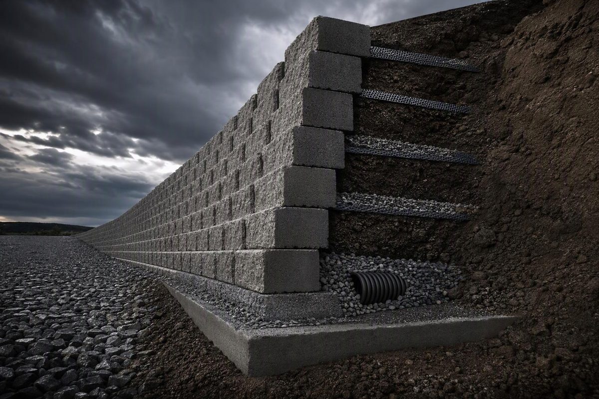
Interlocking retaining wall blocks are dry-stacked concrete units used to form a segmental retaining wall (SRW). Lips, lugs, pins, clips or aggregate-filled cores transfer shear between courses and often establish the setback. This interlock aligns the face and helps resist course-to-course sliding; it does not make the block face alone capable of retaining soil at any height.
A conventional gravity SRW relies mainly on the weight, depth, batter and shear capacity of its units. A reinforced SRW combines the facing with compacted soil and horizontal geogrid layers, creating a much wider composite gravity mass. That reinforced mass resists the external forces associated with taller walls, surcharges and difficult soil conditions (CMHA).
Choose the system before the face
| Site condition | Likely approach | Main consequence for the drawing |
|---|---|---|
| Low wall, level grade, suitable soil, no surcharge | Conventional gravity SRW may be suitable | Capacity depends on the selected block, batter, soil and geometry |
| Greater height or a slope behind the wall | Geogrid-reinforced SRW | Excavation and reinforced fill extend well behind the face |
| Driveway, parking, building, fence or upper wall nearby | Project-specific design is commonly needed | Include surcharge and concentrated loads; coordinate posts and foundations |
| Groundwater, shoreline, steep toe or weak foundation soil | Geotechnical and structural design | Drainage, scour, bearing, settlement and global stability may govern |
Do not select an unreinforced wall from exposed height alone. Manufacturer charts assume a particular unit, soil, backslope and loading condition. Change an input and the chart may no longer apply.
The model 2024 International Building Code requires retaining walls to resist overturning, sliding, excessive foundation pressure and water uplift. It also requires dry-cast concrete units in segmental retaining walls to comply with ASTM C1372 (2024 IBC Section 1807.2). ASTM C1372 addresses unit properties for mortarless construction—not the design of the complete wall. CMHA’s current unit guide identifies ASTM C1372-24 and discusses its dimensional, strength, absorption and freeze-thaw provisions (CMHA).
Define which height is being measured
Show these dimensions separately:
- Exposed height: toe finish grade to the top of the wall.
- Embedment: wall face below toe grade.
- Total or design height: leveling-pad elevation to the top of the wall, including buried courses.
- Retained height: the grade difference producing lateral soil load; on sloping sites it can differ from exposed height.
The distinction affects course counts, engineering and permits. Under the model 2024 IBC, the permit exemption applies to retaining walls not over 4 ft (1.219 m), measured from the bottom of the footing to the top of the wall, unless the wall supports a surcharge or impounds specified liquids (2024 IBC Section 105.2). This is not a universal permission to build: the adopted code, local amendments, residential provisions and zoning rules control.
Where no more specific rule applies, CMHA recommends engineered design when total design height exceeds 4 ft (1.21 m) (CMHA). Engineering can be appropriate at a lower height where a wall supports a driveway, structure, steep slope or another wall, or where weak soil and water complicate the site.
Draw the proprietary block module
Interlocking blocks do not share a universal module. Actual height, face length, depth, weight, setback and connector geometry vary. Identify the selected system, or write performance requirements without combining details from incompatible products.
Two calculations expose coordination problems early:
- Block courses = block-facing height ÷ actual unit height
- Top-face setback = (number of courses − 1) × setback per course
For example, ten 6-in. courses provide 60 in. of block-facing height. With a 3/4-in. setback between courses, the tenth course sits 6 3/4 in. behind the first. A cap adds its own height and overhang. Coordinate those dimensions with property lines, stairs, paving and planting beds.
Curves also require product-specific checking. Because the wall steps into the retained soil as it rises, an inside curve becomes tighter at upper courses. Show the controlling radius and face reference line instead of leaving the curve to field adjustment.
Specify ASTM C1372 compliance along with color range, texture, caps, corners and proprietary connectors. CMHA reports a general dimensional tolerance of 1/8 in. (3.2 mm), with an exception for rough architectural surfaces; consistent unit height matters because these walls have no mortar bed in which to absorb variation (CMHA). For saturated freeze-thaw exposure—and especially where deicing salts are present—require documentation appropriate to the specified exposure. A Federal Highway Administration study found that most blocks examined performed well, including in cold climates, but documented significant deterioration in some field and laboratory cases (FHWA).
Detail the section from the ground outward
A buildable section should identify:
- Foundation soil. Show removal and replacement of unsuitable, organic, loose or compressible material. Design assumptions for bearing and soil strength must match field conditions.
- Leveling pad. State material, width, thickness, elevation and steps. It is commonly compacted, well-graded aggregate rather than a reinforced concrete footing. The first course must be level because every later course follows it.
- Embedment. Provide enough buried facing to protect against erosion and restrain the toe. CMHA suggests 6 in. (152 mm) as an absolute minimum, with greater embedment for taller walls, sloping toes, scour and weak soil (CMHA inspection guide).
- Facing and connectors. State unit orientation, bond, batter, core fill and the correct pins or clips. Substituting connectors can change tested shear and geogrid-connection behavior.
- Gravel fill. Show free-draining aggregate in applicable cores and behind the units. CMHA’s general guidance uses at least 12 in. (305 mm) behind the face.
- Drain and outlet. Show pipe material, diameter, elevation, slope and a positive outlet. CMHA’s general detail uses a minimum 3-in. (76-mm) pipe and daylight outlets no more than 50 ft (15.2 m) apart, but project water conditions should determine the final arrangement.
- Reinforced and retained soils. Define gradation, design shear strength, lift thickness, moisture limits and required density—not merely “compacted fill.”
- Geogrid. Identify product, strength direction, elevations, lengths and face connection. “Geogrid as required” is not construction information.
CMHA gives an initial constraint of at least 0.6 times total wall height or 4 ft (1.2 m) for geogrid length, while emphasizing that actual length, strength and spacing require project-specific external, internal, connection and compound-stability checks (CMHA). Even this minimum reveals a planning constraint: utilities, foundations, easements or a property line may prevent the required excavation behind the face.
Treat drainage and surcharge as site conditions
The gravel column and toe drain are intended to remove incidental water, not to replace site grading, swales, roof-drain routing or subsurface interception (CMHA). Show where collected water discharges. Keep roof leaders, pavement runoff and irrigation out of the reinforced-soil zone. Where fine soil adjoins drainage aggregate, design filter compatibility; a casually placed fabric can itself become a clogged plane.
Driveways, parked vehicles, stockpiles, buildings and upper retaining walls add surcharge. Fence and guard posts can interrupt geogrid and apply concentrated loads near the crest, so their sleeves, foundations and reinforcement details belong in the original design.
Tiering does not automatically create independent short walls. CMHA calls for global-stability review of all tiered SRWs and also identifies groundwater, steep slopes, weak soils and large surcharges as conditions requiring attention to failure surfaces beneath or behind the wall-soil system (CMHA). For comparison with a rigid reinforced-concrete system, see Cantilever Retaining Walls Depend on the Whole System.
Where the wall is close to a walking surface, coordinate fall protection. The model 2024 IBC requires a guard at a publicly accessible retaining wall when the walking surface is within 36 in. (914 mm) of the open side and the drop exceeds 30 in. (762 mm) within the stated measurement zone, subject to local adoption and its exceptions (2024 IBC Section 1807.2.5).
Inspect before each lift disappears
Inspection must follow the work because the critical components are progressively buried. Verify foundation conditions, pad elevation, embedment, unit and connector type, drain outlets, gravel width, fill classification, lift thickness, density, and geogrid product, orientation, elevation and length before the next lift covers them.
CMHA generally limits compacted lifts in the reinforced zone to 6–8 in. (152–203 mm) and advises against heavy self-propelled equipment within 3 ft (914 mm) of the face (CMHA inspection guide). Check level, alignment and batter every course; clean block tops before placing the next course; and correct drift immediately.
The closeout record should preserve approved substitutions, compaction results, drain outlets and geogrid placement. Those concealed elements—not the straightness of the cap alone—show whether the interlocking-block wall was built as the designed soil structure.