
Why Carbon-Fiber Stiffness Cannot Be Reduced to One Number
The applicable value depends on material level: filament, ply, laminate or finished product. It must also match load direction and test basis.
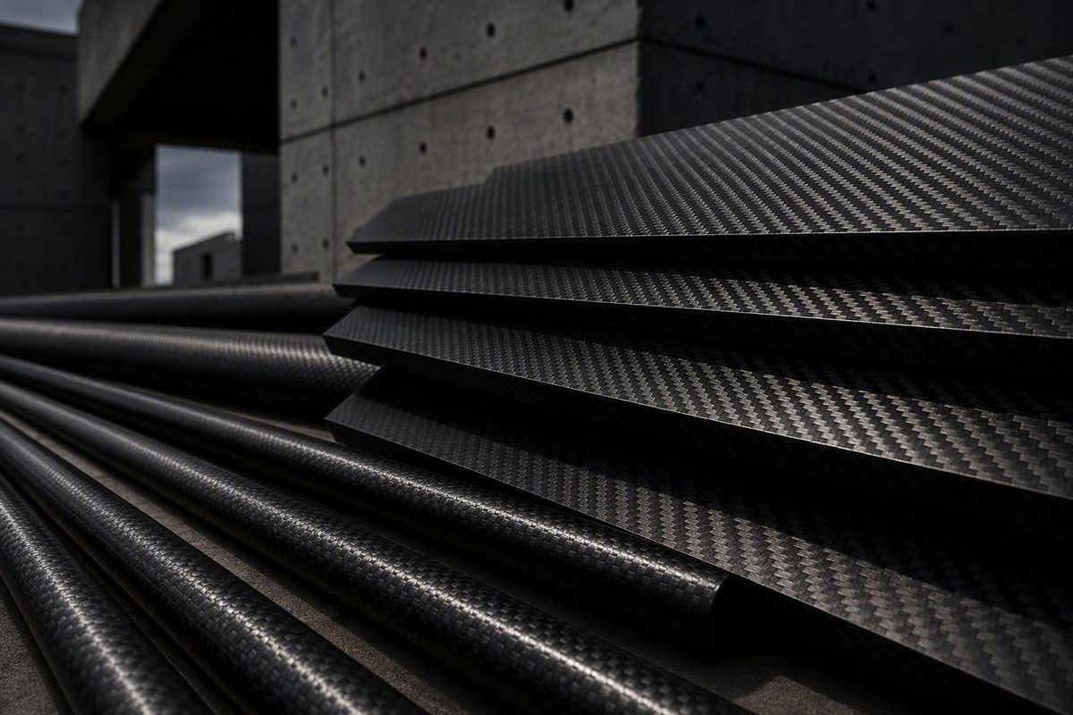
Search for the modulus of elasticity of carbon fiber, and the result may be 70 GPa, 140 GPa, 230 GPa or even 600 GPa. These figures can all describe materials sold under the broad label “carbon fiber,” but they are not interchangeable.
The decisive questions are: Does the value describe a bare filament, a resin-impregnated ply, a complete laminate or a finished product? In which direction was it measured? What fiber, resin, fiber content, layup, manufacturing process, conditioning and test method were used?
For preliminary screening, CFRP manufacturer Uchida reports approximately 70–200 GPa along the fibers and 10–15 GPa transversely. The source does not provide a common test standard, laminate schedule, fiber fraction or supporting dataset, so these should be treated as broad screening figures rather than independently established industry ranges or design values (Uchida’s overview of CFRP Young’s modulus).
Element 6 Composites separately reports 230–600 GPa for high-modulus carbon fiber. That commercial range applies at the fiber level—not to every fiber grade or an ordinary finished laminate (Element 6 Composites’ material comparison).
None of these generic figures should be mistaken for a certified design allowable.
The short answer: typical modulus values and what they describe
There is no single universal modulus of elasticity for carbon fiber. The term may refer to:
- Individual carbon-fiber filaments
- A unidirectional carbon/epoxy lamina
- A woven or multidirectional laminate
- A manufactured sheet, rod, tube, plate or strengthening system
- An effective property assigned to a complete component
The table below separates these material levels and directions. It contains manufacturer- and supplier-reported screening data, not a unified property dataset. All principal values are in gigapascals; for approximate conversion, 1 GPa equals about 0.145 Msi.
| Material form and reporting source | Loading direction | Reported Young’s modulus | Known fiber volume fraction | Evidence limitation |
|---|---|---|---|---|
| General CFRP range reported by Uchida | Along fibers or axial | Approximately 70–200 GPa | Not stated | Manufacturer-reported typical range; no common layup, conditioning or test basis is supplied (Uchida) |
| General CFRP range reported by Uchida | Transverse to fibers | Approximately 10–15 GPa | Not stated | Manufacturer-reported typical range; not universal across resin systems or architectures |
| High-modulus carbon fiber reported by Element 6 Composites | Direction not stated; fiber-level property | Approximately 230–600 GPa | Not applicable as a laminate fraction | Commercial range for high-modulus fiber, not a typical finished CFRP product (Element 6 Composites) |
| Carbon/epoxy sheet, supplier data published by AZoM | Longitudinal | 70 GPa | 50% | Product-specific supplier figure; detailed architecture and test method are not stated (AZoM/Goodfellow supplier data) |
| Carbon/epoxy sheet, same source | Transverse | 70 GPa | 50% | The equal listed values apply to this product entry and should not be generalized |
| High-precision carbon/epoxy tube, same source | Longitudinal | 110–120 GPa | 55–60% | Product-specific supplier figure with incomplete architecture and test information |
| Carbon/epoxy rod, same source | Longitudinal | 120–140 GPa | 55–60% | Product-specific supplier figure, not a universal rod value |
| Carbon/epoxy rod, same source | Transverse | 10 GPa | 55–60% | Product-specific figure illustrating strong directional dependence |
The sheet, tube and rod data are useful because they show how commercial product listings differ. They do not establish a universal relationship between product shape and modulus. The supplier page does not identify detailed reinforcement architecture, specimen dimensions, conditioning, uncertainty or test methods.
The practical short answer is therefore conditional:
- For a rough axial CFRP study, the manufacturer-reported 70–200 GPa range can define an initial sensitivity envelope.
- For a rough transverse study, 10–15 GPa can serve the same limited purpose.
- For a named product, use its direction-specific property and documented test basis.
- For final engineering, use certified or tested data for the actual material system and application.
Young’s modulus measures stiffness, not strength
Young’s modulus, E, describes elastic stiffness under uniaxial loading:
E = \sigma ÷ \varepsilon
where:
- E is Young’s modulus
- \sigma is normal stress
- \varepsilon is normal strain
More generally, modulus is obtained from the slope of the applicable elastic portion of a stress–strain curve. A larger modulus means less elastic strain under the same uniaxial stress, provided the compared values represent the same material direction, loading mode and test context.
If two valid axial tensile moduli are compared under otherwise equivalent conditions, the material with the higher modulus will strain less elastically at a given axial tensile stress. That observation says nothing by itself about which material will carry a greater ultimate load or withstand impact more effectively.
Young’s modulus must remain distinct from:
- Tensile strength: stress associated with tensile failure or another specified limit
- Failure strain: strain reached at failure
- Toughness: ability to absorb energy before fracture
- Fatigue resistance: behavior under repeated or fluctuating loading
- Impact performance: response to rapid, concentrated loading
- Damage tolerance: ability to retain useful performance with defects or damage
Those properties require separate data and acceptance criteria.
Material modulus is also different from component stiffness. The deflection of a plate, beam, tube, façade panel or strengthening system depends on material properties and on:
- Cross-sectional shape and dimensions
- Span and support conditions
- Curvature and shell geometry
- Boundary conditions
- Joint and connection behavior
- Bond-line performance
- Load distribution and load path
- Local instability or buckling modes
A component made from a lower-modulus material can be stiffer than another component if its geometry is more efficient. Conversely, a high-modulus laminate may not produce a stiff assembly if its fibers are poorly oriented, the section is too thin, the joints are flexible or the load bypasses the principal reinforcement.
Terminology matters:
- Young’s modulus normally describes normal stress versus normal strain in tension or compression.
- Shear modulus describes resistance to shear deformation.
- Flexural modulus is obtained from bending behavior under the assumptions of the applicable flexural procedure.
These properties may be related within a material model, but the labels are not interchangeable. The AZoM/Goodfellow rod entry, for example, lists a longitudinal flexural modulus of 125 GPa separately from its longitudinal Young’s modulus of 120–140 GPa (AZoM’s carbon/epoxy supplier-data tables). The flexural result should not be substituted for tensile Young’s modulus merely because it falls within the listed tensile range.
Fiber, lamina, laminate and finished part: four different property levels
A disciplined modulus selection begins by identifying the level at which the property is defined.
- Carbon-fiber filament: An individual reinforcing fiber. Fiber-level modulus describes the filament itself, without the resin content or laminate architecture of a finished part.
- Lamina or ply: A thin resin-impregnated layer with a defined reinforcement direction or fabric arrangement. A unidirectional ply typically has a principal fiber direction and substantially different transverse and shear responses.
- Laminate: Multiple plies assembled in a specified stacking sequence. Its effective response depends on the orientations, order, thicknesses and properties of its constituent plies.
- Finished component: A manufactured plate, tube, wrap, panel, rod or other part. Its behavior incorporates laminate properties, geometry, joints, local features, manufacturing quality and boundary conditions.
Carbon fibers are normally embedded in a polymer matrix. In a well-aligned system, the fibers carry much of the axial load, while the resin transfers load between fibers, keeps the reinforcement positioned and contributes environmental protection. The result is an engineered material system rather than a homogeneous block of carbon.
A fiber-level modulus cannot simply be copied into a laminate or component model. The finished composite contains resin, and the resin is less stiff than the reinforcing fibers. Uchida gives a broad illustrative matrix range of approximately 2–5 GPa, depending on resin type. A laminate may also contain plies directed away from the applied load, reducing effective stiffness in that direction.
Architecture introduces another distinction. These products may all be called carbon fiber while behaving differently:
- Unidirectional tape
- Plain, twill or satin woven fabric
- Non-crimp reinforcement
- A 0/90-degree laminate
- A multidirectional or nominally quasi-isotropic laminate
- A short- or chopped-fiber molding compound
- A pultruded rod or plate
- A wound or braided tube
- A resin-infused panel
- A bonded strengthening plate or field-applied wrap
Even products made with the same nominal fiber grade can have different resin systems, reinforcement fractions, ply schedules, void contents and cure histories.
This is why the commercial 230–600 GPa high-modulus-fiber range cannot be presented as the modulus of a typical CFRP plate, tube, wrap or façade component. Once fibers are combined with resin and arranged into a laminate, the effective property belongs to that composite construction.
For specifications, the noun following “carbon fiber” matters. A filament designation, prepreg system, cured ply, laminate, pultrusion and installed strengthening system are not alternative names for the same property level.
Anisotropy: why loading direction changes the answer
CFRP is anisotropic: its effective elastic response changes with material direction. This differs from the simplified isotropic treatment commonly used for many metals, in which one Young’s modulus is assumed to apply in every direction.
In a unidirectional carbon/epoxy ply, aligned fibers dominate stiffness when the load acts parallel to their axes. Under transverse loading, the response depends much more heavily on the lower-modulus resin and the fiber–matrix system. The same material can therefore have a high longitudinal modulus and a much lower transverse modulus.
The supplier-reported rod illustrates the contrast: 120–140 GPa longitudinally versus 10 GPa transversely, with a listed fiber volume fraction of 55–60%. These are figures for one product, not universal rod properties.
JC Sportline reports another commercial example: 90.1 GPa at 0 degrees and 4.73 GPa at 90 degrees for a particular T300 unidirectional composite. The figures describe that reported system and should not be assigned to every product carrying the T300 name (JC Sportline’s directional composite-property table).
In common laminate notation:
- 0 degrees means the principal fiber direction is aligned with the selected reference axis.
- 90 degrees means the fibers are perpendicular to that reference axis.
- ±45 degrees identifies plies oriented at positive and negative 45-degree angles.
- 0/90 degrees indicates reinforcement in both principal directions, although the relative quantities and ply order still matter.
The coordinate system must be defined. A 0-degree direction may follow a plate’s length, a roll direction, a tube axis or another manufacturer-defined reference. Without that reference, the orientation label is incomplete.
Other architectures redistribute stiffness rather than eliminating directionality:
- Off-axis plies contribute only part of their fiber-direction stiffness to the selected global direction and can introduce coupled normal and shear responses.
- Woven fabrics place reinforcement in at least two yarn directions, but weave geometry and crimp affect the resulting behavior.
- ±45-degree layers can address shear and load transfer rather than maximize stiffness along the global 0-degree axis.
- 0/90-degree laminates support two principal directions, but stiffness in each depends on how much reinforcement is assigned to that direction.
- Multidirectional laminates distribute stiffness among several directions, generally giving up some peak unidirectional stiffness to address multiple load cases.
No universal effective modulus can be assigned to these categories without ply properties and a defined laminate schedule.
Laminate design is therefore a load-path exercise. Fibers should be oriented toward principal loads, but the analysis must also examine transverse stress, in-plane shear, through-thickness effects, joints, holes, terminations and load introduction. Designing only around the strongest direction can overlook the mechanisms that govern the assembly.
An anisotropic or orthotropic material definition ordinarily requires multiple directional Young’s moduli, relevant shear moduli and Poisson effects, all mapped to the laminate’s material axes.
What controls the effective modulus of a CFRP material
The variables governing CFRP stiffness fall into four groups: constituents, architecture, processing, and test or service conditions.
Constituent properties
Fiber grade and fiber modulus: Carbon fibers are available in different grades. A higher fiber modulus can raise composite stiffness when the architecture, bonding and loading direction allow those fibers to contribute effectively.
Resin system: Different resins and cured states should not be assumed to have identical elastic behavior.
Fiber volume fraction: In an aligned longitudinal system, a greater proportion of stiff fiber can increase predicted modulus when other assumptions remain unchanged. Fiber volume fraction is not, however, a complete product description.
Reinforcement architecture
Fiber alignment: Misalignment reduces the reinforcement’s effectiveness along the intended load axis.
Reinforcement form: Continuous unidirectional fibers, woven fabrics, braided forms and cut fibers produce different effective behavior.
Ply orientation: A 0-degree ply contributes differently to axial stiffness than a 45- or 90-degree ply.
Laminate schedule: The number, orientation, order and thickness of plies determine laminate-level response. Two laminates with the same total fiber content can behave differently if the reinforcement is distributed differently.
Processing and production
Manufacturing determines the material actually realized. Relevant considerations include resin distribution, fiber placement, consolidation, cure state, dimensional consistency and production defects. Available evidence does not support universally ranking autoclave molding, resin-transfer molding, hot pressing or other methods without controlled comparisons of equivalent materials.
The supplier products show why association must not be confused with causation. The sheet with 50% fiber volume is listed at 70 GPa, while the tubes and rods with 55–60% fiber volume have higher reported longitudinal values. Their architecture, geometry and test basis are not described well enough to conclude that fiber fraction alone caused the difference.
A peer-reviewed investigation of a T700 board provides a useful warning about product descriptions. The specimen was a cut-fiber sheet-molding-compound board made with a particular resin mixture and vacuum hot-press process—not a continuous unidirectional laminate. It measured 430.5 × 301.5 × 1.88 mm, and processing included hot pressing at 130°C and 2 MPa after 24 hours of thickening and curing (Shen and colleagues’ carbon-fiber-board study).
Results for that board should not be transferred to every product carrying the T700 designation.
Test and service conditions
A property request should identify:
- Production material designation
- Fiber grade and reinforcement form
- Resin system
- Fiber content
- Ply orientations and stacking sequence
- Cure and manufacturing route
- Specimen form and dimensions
- Material direction
- Tension, compression, flexure or shear test mode
- Temperature and moisture conditioning
- Applicable test method
- Statistical basis and production variability
If these conditions matter, obtain conditioned data for the actual product rather than applying an unsupported percentage adjustment.
Estimating longitudinal modulus with the rule of mixtures
For a continuous unidirectional composite loaded along its fibers, longitudinal modulus can be estimated with the rule of mixtures:
E_c = E_fV_f + E_mV_m
with:
V_f + V_m = 1
where:
- E_c = predicted longitudinal composite modulus
- E_f = fiber modulus
- E_m = matrix modulus
- V_f = fiber volume fraction
- V_m = matrix volume fraction
The simplified model assumes an isostrain condition: continuous aligned fibers and matrix experience the same longitudinal strain when the composite is loaded in the fiber direction. Because the fiber is normally stiffer, it carries greater stress at that common strain. Princeton’s composite-materials resource presents the equation for this continuous, uniaxial fiber-reinforced configuration (Princeton’s explanation of the longitudinal rule of mixtures).
Holding constituent properties and assumptions constant, increasing the volume fraction of the stiffer aligned fiber raises predicted longitudinal modulus. That relationship is useful conceptually, but it does not mean that fiber fraction alone determines a manufactured product’s modulus.
Hypothetical calculation
The following values were chosen solely to demonstrate the arithmetic. They do not represent a specified or certified fiber–resin system:
- Assumed fiber modulus, E_f = 230 GPa
- Assumed matrix modulus, E_m = 3 GPa
- Assumed fiber volume fraction, V_f = 0.60
- Assumed matrix volume fraction, V_m = 0.40
Then:
E_c = (230 × 0.60) + (3 × 0.40)
E_c = 138 + 1.2 = 139.2 GPa
The illustrative result is 139.2 GPa. It is not a sourced product value, certified allowable or prediction for a particular laminate.
The equation should not be applied directly to predict:
- A 90-degree transverse modulus
- An off-axis modulus
- Woven-fabric behavior
- A short- or chopped-fiber board
- A multidirectional laminate
- A nominally quasi-isotropic laminate
- A damaged or degraded material
- A finished component with joints and geometric effects
Those cases require direction-specific ply properties and an appropriate composite analysis method. A simple average of fiber and resin moduli is not a substitute for laminate-level analysis.
How carbon-fiber modulus is measured and reported
The conventional tensile approach begins with a coupon whose material direction is identified. The laboratory applies load while measuring force and strain. Stress is calculated using the relevant specimen section, and Young’s modulus is derived from the applicable elastic stress–strain relationship.
A useful report should identify:
- Material and product designation
- Reinforcement and resin
- Fiber direction
- Laminate layup
- Manufacturing process
- Specimen dimensions
- Tabs or gripping arrangement where applicable
- Temperature and conditioning
- Loading rate
- Strain-measurement system
- Modulus-calculation procedure
- Test standard or documented method
Orientation is especially important. A result marked only “carbon-fiber modulus” cannot tell the user whether it represents 0-degree tension, 90-degree tension, bending, an effective laminate direction or another condition.
One published comparison involving an MTM710 carbon/epoxy composite used tensile specimens measuring 25 × 250 mm, designed to match ASTM D3039/D3039M, and calculated Young’s modulus from tensile measurements for numerical modeling. The plaques, layups and test conditions were specific to that investigation, and the available excerpt does not provide a numerical modulus in GPa (the MTM710 experimental and numerical-modeling paper).
That example does not mean one standard governs every carbon-fiber material form. Nor does it establish a universal strain interval for calculating modulus. The procedure must match the material, specimen, loading mode and intended property.
Modal analysis offers a distinct approach. Instead of deriving modulus directly from a conventional uniaxial stress–strain curve, it estimates elastic constants using measured vibration modes and modal parameters, generally in combination with an analytical or computational model of the specimen.
In the T700 cut-fiber board study, experimental and computational modal frequencies differed by less than 5%. The authors reported error rates of 0.7% for elastic modulus and 7.8% for shear modulus, presenting modal analysis as a potentially nondestructive method for testing and quality grading that board (Shen et al., 2022).
Those percentages describe agreement within the study’s method and model; they do not independently establish accuracy against a separate reference. The available material also omits the board’s numerical modulus in GPa, so it cannot provide another entry for a generic property table.
Whether properties come from tensile coupons, modal analysis or another method, their material axes and assumptions must be mapped correctly into the engineering model. A valid 0-degree coupon modulus becomes an invalid input if assigned to the wrong component axis or treated as isotropic.
Choosing a modulus for preliminary design or specification
Choosing a defensible modulus is a staged decision, not a search for the largest number.
1. Define the material form
Determine whether the analysis concerns:
- A carbon-fiber filament
- A unidirectional cured ply
- A woven ply
- A laminate
- A pultruded plate or rod
- A tube
- A strengthening wrap
- A manufactured panel
- A complete installed system
Do not use fiber-level data if the model represents a laminate or finished component.
2. Identify the load direction
Define the required response relative to the fibers and product axes:
- Longitudinal or axial
- Transverse
- Off-axis
- In-plane shear
- Through-thickness
- Flexural rather than tensile
If the source does not identify direction, the modulus is inadequately specified for anisotropic CFRP.
3. Establish the architecture
Record the reinforcement form and laminate schedule. A unidirectional plate cannot automatically be represented by data for a woven sheet, and neither necessarily represents a field-installed wrap. For multidirectional laminates, identify how much reinforcement is assigned to each orientation.
4. Check the test basis
Confirm that the reported property matches the required loading mode and material condition. Look for the test method, specimen orientation, temperature, conditioning, production process and statistical basis.
5. Decide whether the task is screening or final design
For early screening only, Uchida’s broad figures can help establish a sensitivity envelope:
- Axial CFRP: approximately 70–200 GPa
- Transverse CFRP: approximately 10–15 GPa
These ranges are too broad and insufficiently documented for final structural decisions. If a prediction changes materially between the lower and upper bounds, product selection and testing should not be deferred.
For a known commercial sheet, tube, rod, strengthening plate, wrap or façade element, use the product’s certified direction-specific datasheet. If a manufacturer offers several grades, do not select the highest value unless the specified and delivered material corresponds to that grade.
For final structural analysis, the property set should represent the exact:
- Fiber and resin system
- Reinforcement form
- Fiber volume fraction
- Ply schedule
- Manufacturing route
- Production quality
- Loading direction
- Conditioning
- Test method
- Statistical or allowable basis
An anisotropic finite-element model generally needs more than one Young’s modulus. Depending on the material idealization, it may require longitudinal and transverse Young’s moduli, relevant shear moduli, Poisson’s ratios, material-axis definitions and separate strength or failure data. The property set should be internally consistent rather than assembled from unrelated internet tables.
A practical datasheet checklist is:
- Material or product designation
- Fiber grade
- Reinforcement form
- Resin system
- Fiber volume fraction
- Ply stacking sequence
- Coordinate-axis definition
- E_1, axial or longitudinal modulus
- E_2, transverse modulus
- Relevant shear modulus
- Relevant Poisson’s ratio
- Tensile versus compressive basis
- Test standard and calculation method
- Specimen conditioning
- Test temperature
- Number of specimens
- Mean, minimum, characteristic or allowable status
In building work, CFRP strengthening plates, wraps and lightweight components must be evaluated as specified systems. Product certification, testing and applicable project requirements should be established for the specific application by the responsible design team.
Watch for these red flags:
- A modulus with no material form
- No fiber or laminate direction
- No resin or reinforcement description
- No test mode or method
- A high-modulus fiber value used for a finished laminate
- Flexural modulus substituted for tensile Young’s modulus
- A 0-degree value assigned to every material axis
- Data combined from unrelated products
- Vendor marketing treated as a structural design allowable
- A generic isotropic modulus entered into an anisotropic material model
The reliable selection rule is straightforward: identify whether the value describes a filament, ply, laminate or finished product; match it to the load direction; and verify the material system and test basis. Broad axial and transverse ranges can orient an early study, but specifications, structural calculations and finite-element models should rely on certified direction-specific properties for the actual CFRP system.
Is the modulus of elasticity of carbon fiber 230 GPa?
It can be, but the statement is incomplete. A value near 230 GPa may describe a particular carbon-fiber grade or serve as an assumed constituent value. It does not automatically describe a cured ply, laminate or finished component.
Element 6 Composites places that value at the lower end of its commercial 230–600 GPa range for high-modulus carbon fiber. Before using it, identify whether the property belongs to the filament, cured lamina or complete product and confirm its direction and test basis.
Why can carbon/epoxy be 120–140 GPa longitudinally but only 10 GPa transversely?
Along the supplier-reported rod’s longitudinal axis, aligned carbon fibers make a large contribution to stiffness. Across the fibers, the response depends much more on the lower-modulus polymer matrix and fiber–matrix system.
The values describe two directions in one anisotropic product. They are not conflicting measurements of an isotropic property.
Is Young’s modulus the same as flexural modulus or tensile strength?
No. Young’s modulus describes elastic normal stress versus normal strain, usually in uniaxial tension or compression. Flexural modulus is derived from bending behavior under a flexural procedure. Tensile strength describes stress associated with failure or another specified tensile limit.
Modulus indicates stiffness, not failure capacity. The properties should not be substituted for one another simply because their numerical values appear similar.
Can the rule of mixtures be used for woven or quasi-isotropic carbon-fiber laminates?
Not in its simple longitudinal form. The equation E_c=E_fV_f+E_mV_m represents a continuous, aligned, isostrain composite loaded along its fibers.
Woven and multidirectional laminates contain reinforcement at multiple orientations and may include yarn crimp and coupled directional behavior. Their effective properties require direction-specific ply data and an appropriate laminate analysis method.
Can a generic CFRP modulus be entered directly into an FEA model?
Only for a deliberately simplified preliminary sensitivity study, with the limitation made explicit. A generic modulus should not be treated as sufficient for final analysis.
A detailed CFRP model normally requires defined material axes and a consistent set of directional elastic properties, including the applicable Young’s moduli, shear moduli and Poisson effects. Inputs should match the actual fiber, resin, laminate schedule, manufacturing condition and test basis.