
From Bridge Bracing to Dense Networks: One Term, Two Technical Ideas
In structures, it is a K-shaped web that creates physical load paths. In graph theory, each retained edge needs at least k−2 triangles under NetworkX.
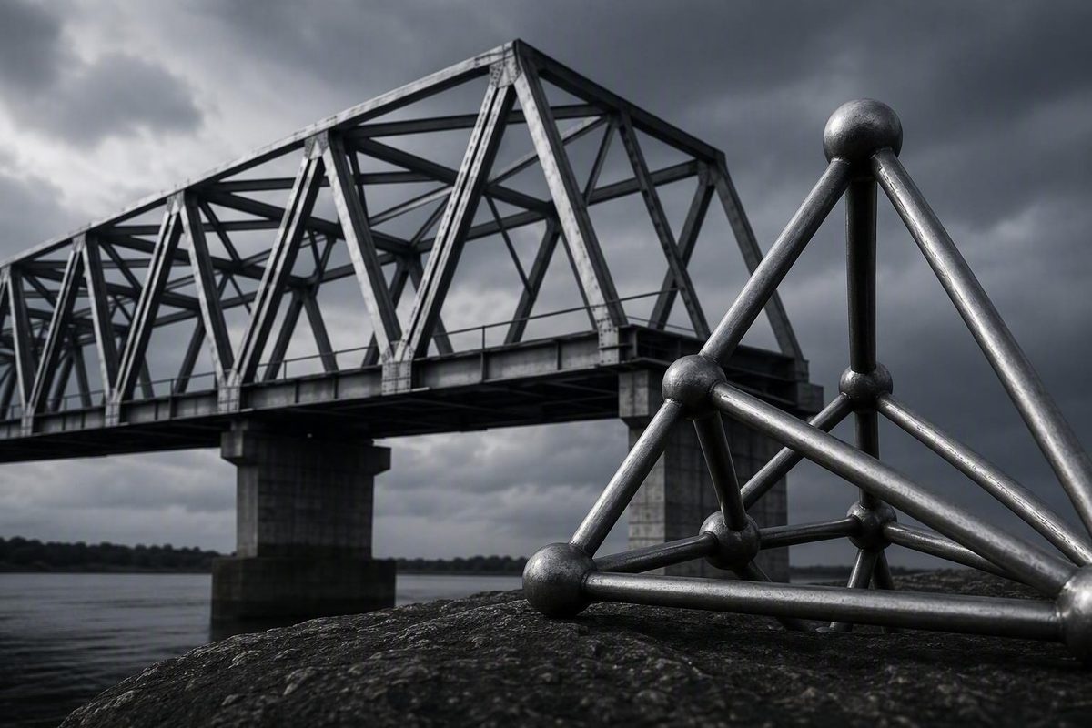
First, which kind of K truss do you mean?
Two meanings, two fields
- Structural K-truss: a physical bridge or bracing configuration in which vertical and oblique web members form K-shaped panels between top and bottom chords.
- Graph k-truss: a graph-analysis concept in which every retained edge belongs to a specified minimum number of triangles within the retained subgraph.
Search results mix these subjects because the same term is used independently in structural engineering and graph theory. They are not versions of one system, and calculations from one field have no application in the other.
This article uses K-truss with a capital K for the structural configuration and k-truss, with a variable k, for the graph concept. The distinction is a navigation aid rather than a universal naming rule.
Triangles are central to both meanings, but they serve different purposes:
| Field | What triangles represent |
|---|---|
| Structural engineering | Geometric arrangements of physical members that create load paths |
| Graph analytics | Relationships among three vertices, used to measure how strongly an edge is embedded among shared neighbors |
In structural terms, a K-truss has top and bottom chords connected by a web in which a vertical member and two oblique members create the characteristic K-shaped arrangement. The supplied structural material discusses the form mainly in relation to bridges and describes steel as usual while noting that timber is possible (Structural Basics’ K-truss overview).
Under the NetworkX convention, a k-truss is a maximal qualifying subgraph with at least three vertices in which every retained edge belongs to at least k − 2 triangles within that subgraph (NetworkX k_truss documentation).
The structural sections below address anatomy, idealized analysis, load-dependent member forces, and selection boundaries. The graph sections explain triangle support, iterative pruning, unsuitable networks, and safe use of NetworkX.
The structural discussion is educational. It cannot replace project-specific analysis and design by a qualified structural engineer for a real bridge, tower, building, connection, temporary condition, or load case.
Structural K-truss anatomy: chords, web members, joints, and supports
A structural K-truss belongs to the broader truss family: assemblies of comparatively slender members connected at joints and organized around triangular geometry. Its identity comes from its web layout, not from a particular material, span, connection detail, or guaranteed force pattern.
Its principal parts are:
- Top chord: the upper longitudinal boundary of the truss.
- Bottom chord: the lower longitudinal boundary.
- Vertical members: web members running between chord levels.
- Oblique or diagonal members: sloping web members connecting the intermediate point on a vertical to other chord joints.
- Joints or nodes: points at which members meet.
- Panel: a portion of the truss between successive principal chord joints or panel lines.
- Supports: interfaces through which reactions pass into piers, abutments, columns, foundations, or another supporting system.
A simplified K-shaped panel can be shown as follows:
Top chord joint      o──────────────o
                     │           ╱
Full vertical        o  Intermediate joint
                     │           ╲
Bottom chord joint   o──────────────o
                     ↑
              Vertical member
The two oblique members run from the intermediate joint on the vertical to the upper-right and lower-right chord joints. Together with the vertical, they resemble the stem and arms of the letter K. In a multi-panel truss, adjacent panels complete the overall web, and K orientations may be mirrored around the span.
Diagram note: This sketch identifies geometry only. It is not a connection detail, member-force diagram, or design-ready structural model.
What each part does
The chords provide the main longitudinal load path. That broad description does not establish the sign or magnitude of force in every chord segment; those results depend on the geometry, supports, joints, and load case.
Web members transfer forces between the chords and help carry applied loads toward the supports. They also divide the structure into triangular units. Unlike a four-sided pin-jointed arrangement, an ideal triangle cannot change shape without at least one side changing length. That geometric principle explains why triangulation is useful, but it does not establish the capacity of a real truss.
Joints organize the load path. In a textbook model, they may be treated as frictionless pins so that connected members transfer axial force without joint moment. Real joints use plates, bolts, welds, pins, timber fasteners, or other details and do not necessarily behave as perfect mathematical hinges.
Supports complete the idealized system. A common classroom model places a pin at one end and a roller at the other. In a two-dimensional model, the pin provides horizontal and vertical reaction components, while the roller provides one reaction in its restrained direction. Those symbols are modeling assumptions; actual bearings and substructures must be represented according to their real restraint and movement characteristics.
How the K layout differs from other trusses
One supplied discussion describes the K-truss as a Parker-truss variant and the Parker as derived from the Pratt. That provides useful historical and geometric context, but it does not mean every bridge called a K-truss must have a Parker-style polygonal top chord. Modified and hybrid arrangements can complicate naming (Garrett’s Bridges discussion of the K-truss form).
Other familiar truss arrangements divide the web differently:
- A Pratt truss typically has verticals and diagonals that slope toward the span center.
- A Howe truss reverses the characteristic diagonal orientation associated with the Pratt.
-
A Warren truss uses repeating, alternating triangles and may include added verticals.
-
A K-truss uses shorter vertical and oblique subdivisions meeting at intermediate points.
These descriptions identify geometry, not universal performance rankings. A K-shaped web is not automatically stronger, lighter, cheaper, or more efficient than a Pratt, Howe, Warren, or Parker arrangement.
Geometry is not behavior
Recognizing a K shape identifies how members are arranged. It does not determine:
- the force in a member;
- whether that member is in tension or compression;
- whether the truss is stable or statically determinate;
- how much it deflects;
- whether a joint acts as pinned, fixed, or semi-rigid;
- or whether a member or connection has adequate capacity.
Those questions require dimensions, sections, materials, supports, connection details, load cases, and a suitable analytical model. Geometry is the beginning of structural interpretation, not its conclusion.
How a structural K-truss carries load—and why forces can reverse
At a broad level, load enters a bridge through the deck or another supported system, reaches the truss at joints or through its floor system, passes through the web and chords, and leaves through support reactions.
Hand calculations simplify that physical system. Common ideal planar-truss assumptions are:
- Members are straight and meet at their centerlines.
- Joints are frictionless pins.
- External loads and support reactions act at nodes.
- Each member is a two-force element.
- Member action is limited to axial tension or compression.
- Secondary bending and shear are neglected.
These assumptions make equilibrium-based analysis possible. They do not describe every aspect of a fabricated bridge. The method of joints and method of sections are likewise presented as methods for idealized pin-connected, axially loaded trusses (CalcTree’s truss analysis guide).
A conceptual bridge load path
Consider a downward load applied at a top-chord joint:
- The loaded joint must satisfy horizontal and vertical equilibrium.
- Axial forces develop in the chord and web members meeting at that joint.
- The web transfers force between the upper and lower parts of the truss.
- Chord forces change from panel to panel as the global bending effect changes.
- The combined member forces ultimately balance the reactions at the supports.
Every joint must balance, as must the structure as a whole. Change the geometry, support conditions, joint model, or loading, and the equilibrium solution may also change.
Do verticals compress while diagonals stretch?
Not as a universal rule. Such a pattern may occur in selected members under a particular gravity-load case, but tension and compression depend on:
- member location;
- load position and direction;
- truss depth and panel geometry;
- support restraint;
- connection assumptions;
- and the load case being checked.
One published K-truss comparison depicts the same total top load applied first across the span and then as a central concentrated load. In that particular model, the reported chord forces changed relatively little while internal web forces changed substantially; some upper vertical members reportedly reversed from tension to compression.
The source does not provide enough geometry, equations, support information, or analytical detail to reproduce its force diagrams. Its defensible lesson is therefore narrow: the depicted model reports that web-member force signs and magnitudes changed when the load pattern changed. Its values should not be reused as a general K-truss force diagram.
Force reversal matters because a member that carries tension in one analyzed condition may carry compression in another. An analysis based on only one convenient gravity-load pattern cannot establish every member’s required behavior.
Why shorter compression segments may help
A central rationale for the K layout is that intermediate joints can divide a longer compression member into shorter segments. If those joints provide the assumed restraint, the shorter effective length can reduce slenderness-related buckling susceptibility.
The qualification is essential. The simplified claim also does not account for section properties, end conditions, member imperfections, material behavior, connection response, out-of-plane restraint, or deformation of the surrounding truss.
The K layout may therefore create shorter compression segments, but it does not eliminate compression, prevent buckling, or guarantee adequate capacity.
A bridge is not a tower turned through 90 degrees
K-shaped bracing can form part of a vertical tower, but bridge force patterns cannot simply be rotated and assigned to it. Tower forces depend on the tower geometry, supports, loads, restraints, and three-dimensional behavior.
A limited user-generated engineering discussion reaches the same high-level conclusion: tension and compression should be calculated for the actual tower and its governing load conditions rather than inferred from the visual direction of its K bracing (discussion of vertical K bracing in towers). Because that source provides no complete geometry or calculation procedure, it supports only this general caution—not a tower-design method.
Idealized K-truss analysis: reactions, nodal loads, and member forces
A hand analysis can build intuition and provide an equilibrium check for a more elaborate model. It should begin with an explicit model rather than with isolated force calculations.
Step 1: Define the geometry and labels
Prepare a dimensioned diagram showing:
- every joint and member;
- panel widths and truss depth;
- chord profiles;
- support locations;
- load application points;
- and consistent joint and member labels.
Labels must remain consistent across the diagram, equations, and results. A force called N9 in an equation must refer to the same physical member wherever it appears.
Step 2: State joint and support behavior
Specify whether joints are pinned, fixed, semi-rigid, or mixed. In the classic axial-only hand model, joints are pinned and member centerlines intersect at nodes.
A common two-dimensional support model uses:
- a pin, restraining horizontal and vertical translation; and
- a roller, restraining translation in one direction while allowing movement in another.
That arrangement commonly produces three external reaction components, but it does not by itself prove that the truss is statically determinate. Determinacy and stability depend on the complete arrangement of members, joints, reactions, geometry, and any internal releases.
Step 3: Establish load cases
Define each load pattern before solving the structure. An educational exercise might use a point load, equivalent nodal gravity loads, or a lateral load. Each pattern produces its own equilibrium solution.
If chord members are intended to behave as axial two-force elements, loads should enter at joints. Applying a continuous line load directly to a chord would generally require that chord to resist effects between joints. To retain the axial-only idealization, the line load may instead be converted into equivalent nodal loads using tributary lengths.
It is not valid merely because the resulting numbers are convenient.
Step 4: Calculate global support reactions
Isolate the entire truss and apply planar equilibrium:
\sum F_x = 0
\sum F_y = 0
\sum M = 0
Solve the reactions before balancing individual joints or cutting through members. Symmetry is useful only when both the structure and the load pattern are symmetric.
A published illustrative model converts a line load of 200 kN/m into 300 kN at each of two end nodes and 600 kN at each of seven intermediate nodes (Structural Basics’ worked K-truss calculation). The represented vertical load is therefore:
2(300) + 7(600) = 4,800 kN
For that source-specific symmetric pin-and-roller model, the reported reactions are:
R_Ax = 0
R_Ay = R_By = 2,400 kN
These reaction values can be checked from global equilibrium because the load total and symmetry are stated. They apply only to that example.
The source also reports selected axial member forces, but the supplied material does not reproduce the complete dimensioned geometry and member diagram needed to verify or meaningfully interpret those values here. They are therefore omitted rather than presented as transferable K-truss results.
The example appears to contain an internal labeling inconsistency as well: one displayed solution names a calculated diagonal N3, while the preceding equilibrium equation and later work identify it as N9. Anyone reconstructing the calculation should resolve that discrepancy against the original member diagram rather than silently copying either label.
The source’s sign convention defines:
- positive axial force as tension; and
- negative axial force as compression.
Other software or textbooks may use different conventions, so signs should always be defined with the results.
Step 5: Use the method of joints
The method of joints isolates one node at a time. For a planar pin joint:
\sum F_x = 0
\sum F_y = 0
A practical sequence is:
- Start at a joint with no more than two unknown member forces.
- Assume unknown member forces act away from the joint, representing tension.
- Resolve inclined forces into horizontal and vertical components.
- Solve the two equilibrium equations.
- Interpret a negative result as compression under the assumed convention.
- Continue to an adjacent joint where known forces reduce the number of unknowns.
The initial arrow direction is a bookkeeping convention. It does not predetermine whether the physical result is tension or compression.
Step 6: Use the method of sections where appropriate
The method of sections passes an imaginary cut through the truss and isolates one side. It can determine selected member forces without solving every intervening joint.
Apply:
\sum F_x = 0,\qquad \sum F_y = 0,\qquad \sum M = 0
Taking moments about the intersection of two unknown force lines can eliminate both from one equation, allowing the third force to be found directly.
What changes with fixed or mixed connections?
A fixed or semi-rigid connection can transfer moment as well as axial force and shear. Continuous chords may also bend between panel points. Once those effects are included, a pure two-force-member model no longer represents the complete response.
Changing the connection model can change calculated stiffness, force distribution, connection actions, and deflection. A mixed model may represent a fabricated truss more closely than an all-pinned model, but only when it reflects the actual details. Pinned and fixed assumptions are not interchangeable options that may be selected according to which produces the preferred answer.
What the hand model leaves out
An axial, linear, planar solution does not itself calculate:
- member bending and shear;
- connection eccentricity or stiffness;
- out-of-plane response;
- deformation compatibility;
- local or global buckling;
- imperfections;
- fatigue;
- moving-load envelopes;
- support movement;
- construction-stage behavior;
- nonlinear material response;
- or second-order effects.
The hand model remains useful for learning equilibrium and checking whether reactions and joint forces balance. It is not a complete bridge design.
Structural advantages, trade-offs, and comparison boundaries
The most defensible potential advantage of the K layout is geometric: it can divide a longer compression member into shorter segments. If the intermediate joints and surrounding members provide effective restraint, that subdivision may reduce effective length and buckling susceptibility.
The corresponding trade-off is also geometric. Subdivision requires additional members and joints, potentially increasing:
- the number of pieces and connections to detail;
- fabrication and fit-up work;
- erection coordination;
- and the number of elements requiring inspection.
That does not establish a universal cost result. A valid comparison would require matched designs and project-specific evidence. Claims that K-trusses are always cheaper, more expensive, stronger, lighter, rare, or inefficient go beyond what the supplied evidence establishes.
Geometry-focused comparison
| Truss type | Characteristic geometry | Interpretation boundary |
|---|---|---|
| K-truss | Vertical members and pairs of oblique members create K-shaped subdivisions | The K shape does not assign permanent tension or compression roles |
| Pratt | Verticals with diagonals generally sloping toward the span center | Familiar force patterns depend on the assumed supports and loading |
| Parker | Pratt-family web with a polygonal or varying-depth top chord | Varying depth does not establish universal superiority |
| Warren | Repeating alternating triangles, sometimes with added verticals | Variants differ, so the name alone may not define the full model |
| Howe | Verticals with characteristic diagonals oriented opposite those of a Pratt | Traditional force descriptions remain load- and model-dependent |
A bridge supplier’s overview similarly distinguishes K, Pratt, Howe, and Warren arrangements primarily through their chord and web geometry. Its fixed tension-and-compression descriptions should be read as simplified patterns rather than universal rules (Areté Structures’ truss-layout comparison).
What a fair comparison requires
A meaningful comparison should hold major project conditions constant, including:
- span, depth, and panel arrangement;
- deck position and load-entry points;
- support and joint assumptions;
- materials and section properties;
- applicable load cases;
- member restraint assumptions;
- fabrication and transportation constraints;
- erection requirements;
- inspection access;
- and the intended service criteria.
Only then can weight, deflection, member utilization, connection count, fabrication effort, or cost be compared on a common basis.
The bare side truss should not be confused with the entire bridge system. A web arrangement that appears economical in isolation may interact differently with the deck, floor system, lateral bracing, bearings, or erection sequence.
A practical decision checklist
The following is a non-exhaustive set of general project questions, not a K-truss design procedure:
- Does the available structural depth suit the proposed geometry?
- Where do loads enter the truss?
- Which load patterns govern each member?
- Do any web members reverse force?
- Are compression segments restrained as assumed?
- How will intermediate K joints be represented and detailed?
- Are connection eccentricities significant to the model?
- Can the members and connection assemblies be fabricated and transported?
- Is the structure stable during erection as well as in its completed state?
- Can the relevant members and connections be inspected?
- How does the complete bridge system compare with alternative geometries?
The answer may favor a K arrangement, another truss, or a different structural system. Selection should follow the project model and requirements rather than a generic reputation.
They can demonstrate equilibrium, workmanship, and failure modes, but their materials, adhesives, scaling, joint stiffness, and loading differ from those of full-scale structures. Model-bridge anecdotes should remain separate from full-scale engineering evidence.
Graph-theory k-truss: the k-2 triangle rule
A graph k-truss has no physical chords, supports, reactions, or loads. It operates on vertices and edges.
Suppose an undirected graph contains vertices u, v, and w, with all three possible edges:
(u,v),\quad (v,w),\quad (w,u)
Those edges form a triangle. The support of an edge is the number of triangles containing that edge in the current subgraph.
If u and v have five common neighbors, and the necessary edges remain in the subgraph being evaluated, edge (u,v) has support 5.
Under the NetworkX convention, every edge e retained in a k-truss must satisfy:
support(e) \geq k-2
The support is evaluated inside the retained subgraph, not just once in the original graph.
The smallest example: one triangle
Consider a graph consisting of one triangle:
A ----- B
/
/
    C
Each edge belongs to exactly one triangle. For k=3:
k-2 = 3-2 = 1
Every edge has support 1, so the graph qualifies as a 3-truss under the NetworkX convention.
For k=4, every edge would need support of at least 2. The isolated triangle would fail, leaving no qualifying 4-truss.
Why support differs from degree
A vertex’s degree counts its incident edges or neighbors. Edge support instead counts shared-neighbor triangles.
The center of a star can have many neighbors while none of those neighbors connect to one another. Its degree is high, but the graph contains no triangles. A k-truss therefore asks a more specific question: is every retained edge reinforced by enough common neighbors?
K-truss filtering can be understood as a relaxation of clique discovery. A clique requires every pair of vertices in the set to be connected. A k-truss can contain missing edges as long as each retained edge has sufficient triangle support.
That does not make every k-truss a meaningful community. Triangle support is informative only when triangles correspond to something relevant in the network being studied.
The convention warning
Not every paper or library assigns the same meaning to k.
NetworkX requires at least k-2 triangles per retained edge. Some literature instead uses the label k-truss for a subgraph in which every edge belongs to at least k triangles. NetworkX explicitly documents this two-unit difference and states that its implementation uses the k-2 convention.
| Triangle threshold per edge | NetworkX label | Alternative threshold-equals-label convention |
|---|---|---|
| 1 | 3-truss | 1-truss |
| 2 | 4-truss | 2-truss |
| 5 | 7-truss | 5-truss |
Thus, “we calculated a 6-truss” is incomplete unless the convention is stated.
NVIDIA’s nightly cuGraph page presents the edge-based k-2 rule, but other wording on that page inconsistently refers to vertices and a subgraph of k nodes. The coherent edge-support definition should control any interpretation of that page (NVIDIA cuGraph k-truss documentation).
How graph k-truss pruning works—and when it is the wrong tool
A k-truss is commonly extracted by iterative pruning. Support is not fixed: removing one edge destroys every triangle containing it, which can reduce the support of neighboring edges.
A basic procedure is:
- Count the support of every edge in the current graph.
- Set the threshold to k-2.
- Identify edges whose support is below that threshold.
- Remove those edges.
- Update support for edges in affected triangles.
- Repeat until every remaining edge satisfies the threshold.
A one-time support count in the original graph is generally insufficient because an edge can lose support as surrounding edges are removed.
A cascading 4-truss example
Consider two triangles sharing edge AB:
    C
/ \
  A---B
/
    D
The edges are:
AB, AC, BC, AD, BD
Initially:
- AB belongs to triangles ABC and ABD, so its support is 2.
- AC, BC, AD, and BD each have support 1.
For a NetworkX-style 4-truss:
4-2 = 2
The four outer edges fail because each has support 1. Removing them destroys both triangles. Edge AB, which initially met the threshold, is then left with support 0 and also fails.
The graph therefore has no nonempty 4-truss. This is the central cascade: an edge can satisfy the threshold in the original graph and fail after neighboring edges are pruned.
k-core versus k-truss
A k-core is based on vertex degree: vertices below the selected degree threshold are repeatedly removed. A k-truss is based on edge support: edges belonging to too few triangles are repeatedly removed.
A cycle of four or more vertices illustrates the difference. Every vertex can have degree 2, allowing the cycle to survive an appropriate core filter. Yet the cycle contains no triangles, so it cannot support a NetworkX 3-truss.
Triangle support therefore imposes a different local-cohesion condition from degree alone.
Core-then-truss preprocessing
A corresponding core calculation can be used to reduce the candidate graph before triangle-support processing. Vertices that cannot meet the necessary neighborhood condition need not remain in the truss candidate.
This preprocessing may reduce later work, but it does not guarantee a speedup. The result depends on graph structure, preprocessing cost, selected k, data representation, memory behavior, hardware, and implementation.
The University of Texas ISS Group describes iterative pruning, a core-then-truss variant, and parallel visibility models. Its reported benchmark uses a particular protein graph, implementation, compiler, operating system, and multi-package Intel Xeon system, so it is not a general performance ranking (UT Austin ISS k-truss benchmark documentation).
Jacobi-style and immediate-visibility rounds
In a Jacobi-style process, edges identified for removal in one round remain visible to other computations until the next round. The consequences of those removals therefore appear in the following iteration.
In an immediate-visibility bulk-synchronous process, a removal can become visible during the current round. Other edges may discover their reduced support sooner, potentially reducing the number of rounds.
Fewer rounds do not necessarily mean lower total runtime.
Networks for which k-truss is uninformative
K-truss analysis depends on triangles. It therefore yields little or no structure in:
- trees, which have no cycles and therefore no triangles;
- bipartite graphs, which have no odd cycles and therefore no triangles;
- long chains and sparse path-like networks;
- and other triangle-poor graphs, even when some vertices have high degree.
K-truss is not a path-finding algorithm: it does not calculate shortest routes, reachability, or flow. Nor is it a universal solution for community discovery. A returned subgraph may contain multiple connected components, and triangle-rich structure does not automatically correspond to a meaningful social or operational group.
Use k-truss when triangle-supported edges answer the analytical question—not merely because the data can be represented as a graph.
Using NetworkX k_truss safely
NetworkX provides k_truss(G, k) for undirected simple graphs. A concise example is:
import networkx as nx

G = nx.Graph()

G.add_edges_from([
    ("A", "B"), ("B", "C"), ("C", "A"),  # triangle ABC
    ("A", "D"), ("B", "D"),               # triangle ABD
    ("D", "E")                            # unsupported tail
])

H = nx.k_truss(
    G,
    3  # NetworkX requires at least k - 2 triangles per retained edge
)

print("Nodes:", sorted(H.nodes()))
print("Edges:", sorted(tuple(sorted(edge)) for edge in H.edges()))
For k=3, every retained edge must belong to at least one triangle. Edge DE belongs to none and is removed. Vertex E then has no retained edge, while the two triangles sharing AB remain.
Support in the result can be inspected as follows:
for u, v in H.edges():
    common_neighbors = set(H[u]).intersection(H[v])
    support = len(common_neighbors)
    print((u, v), support)
The count is performed in H, not the original G, because the defining support condition applies inside the qualifying subgraph.
Validate the graph before calling the function
NetworkX 3.6.1 documents k_truss for undirected graphs. It returns a NetworkX graph containing the qualifying subgraph, with graph, node, and edge attributes copied. Directed graphs, multigraphs, and graphs containing self-loops are unsupported and raise NetworkXNotImplemented.
A defensive preparation function might be:
import networkx as nx

def prepare_for_k_truss(G):
    if G.is_directed():
        raise TypeError("k_truss requires an undirected graph")

    if G.is_multigraph():
        raise TypeError(
            "Convert parallel edges using an explicit documented rule"
        )

    H = G.copy()
    H.remove_edges_from(nx.selfloop_edges(H))
    return H

G_clean = prepare_for_k_truss(G)

T = nx.k_truss(
    G_clean,
    4  # NetworkX k - 2 convention: threshold is 2 triangles
)
Converting a directed or multigraph input is a data-model decision, not routine cleanup. Replacing directed relationships with undirected edges discards direction. Collapsing parallel edges can discard multiplicity, weights, or attributes. Any such transformation should be documented.
Record the convention with every result
A reproducible result record could include:
Algorithm: k-truss
Library: NetworkX
Version: 3.6.1
Convention: each retained edge has support >= k - 2
k: 5
Triangle threshold: 3
Input: undirected simple graph
Self-loops: removed
Parallel edges: not present
Component handling: inspected after extraction
A threshold of three triangles per edge would be called:
- a NetworkX 5-truss, because 5-2=3; or
- a 3-truss under the alternative threshold-equals-label convention.
Recording only k=5 can therefore create silent comparison errors.
Inspect the output, not just its size
A qualifying result can contain more than one connected component:
print(H.number_of_nodes())
print(H.number_of_edges())

components = [
    H.subgraph(nodes).copy()
    for nodes in nx.connected_components(H)
]

for i, component in enumerate(components, start=1):
    print(
        i,
        component.number_of_nodes(),
        component.number_of_edges()
    )
Whether those components should be reported together or analyzed separately depends on the task.
Testing nearby values of k is also useful:
for k in range(3, 7):
    T = nx.k_truss(G_clean, k)
    print(k, T.number_of_nodes(), T.number_of_edges())
The goal is not necessarily to find the largest k that leaves any result. A high threshold may retain only a tiny pocket, while a low threshold may preserve nearly every triangle. Parameter selection should reflect the domain question and be accompanied by sensitivity checks.
Alternative backends and performance claims
NetworkX lists GPU-accelerated cuGraph and OpenMP-enabled GraphBLAS as alternative implementations. Their availability does not establish which backend will be fastest for a particular graph.
A benchmark on one graph and hardware configuration should not be treated as a general speed guarantee.
Result-checking checklist
Before accepting a k-truss result:
- Confirm that the graph is undirected.
- Confirm that it is a simple graph rather than a multigraph.
- Remove or explicitly handle self-loops.
- Document conversions from directed, weighted, or parallel-edge data.
- State whether the threshold is k-2 or k triangles per edge.
- Count support in the retained subgraph.
- Inspect connected components if separate regions matter.
- Test nearby values of k.
- Check whether the surviving subgraph is meaningful for the task.
- Record the library, version, preprocessing, and convention.
- Do not interpret triangle density as community, trust, or importance without domain evidence.
Frequently asked questions
Is a structural K-truss the same thing as a graph-theory k-truss?
No. A structural K-truss is a physical arrangement of chords and web members used to transfer loads. A graph k-truss is a subgraph selected according to triangle support around its edges. Their shared name and use of triangular patterns do not make their calculations or meanings interchangeable.
Are K-truss verticals always in compression and diagonals always in tension?
No. That may describe selected members in a particular model, but it is not a universal rule. Force signs depend on member position, geometry, supports, joint assumptions, and loading. A change in load pattern can alter web forces and may reverse some members between tension and compression.
Can a K-truss arrangement be used vertically in a tower?
K-shaped bracing can form part of a tower system, but it must be analyzed using the actual tower geometry, supports, restraints, and load cases. Bridge force patterns cannot simply be rotated and applied to a vertical structure.
Why is a triangle a 3-truss in NetworkX?
NetworkX requires every retained edge in a k-truss to belong to at least k-2 triangles. Each edge in a single triangle belongs to one triangle. With k=3, the threshold is 3-2=1, so every edge qualifies.
Can NetworkX compute a k-truss for a directed graph or multigraph?
Not with networkx.k_truss directly. The function requires an undirected simple graph and does not support directed graphs, multigraphs, or graphs containing self-loops. Converting such inputs requires an explicit decision about direction, parallel edges, loops, weights, and attributes.
Conclusion: the name is only the starting point
A structural K-truss is a physical load-carrying arrangement whose behavior depends on geometry, joints, restraints, supports, and load cases. Its K-shaped web identifies the layout but does not determine member forces or establish structural capacity.
A graph k-truss is a triangle-support filter whose output depends on the input graph, iterative pruning, and the chosen definition of k. Under NetworkX, the threshold is k-2 triangles per retained edge, but other sources may label the same threshold differently.
In both fields, trustworthy interpretation begins by stating the definition, assumptions, model, and limits—not by relying on the name alone.