
Geogrid Reinforces the Soil Behind the Retaining Wall
How retaining-wall geogrid works, what determines its length and spacing, and which product, drainage and installation details drawings must resolve.
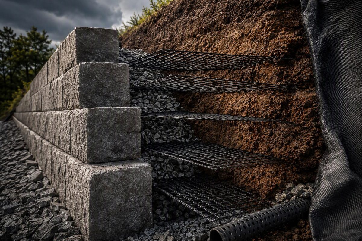
Geogrid for retaining walls is structural soil reinforcement, not drainage fabric. In a reinforced segmental block wall, horizontal grid layers connect to the facing and extend into compacted backfill. The blocks and reinforced soil then act as a wider gravity structure, rather than relying on the blocks’ weight alone. That changes the main coordination question: how much ground behind the wall must be reserved for the reinforced zone? CMHA’s design guidance describes this composite system.
This article concerns geogrid-reinforced segmental retaining walls. For the facing, base, setback and embedment details, see interlocking retaining wall blocks.
What the grid does—and does not do
Geogrid carries tensile force. Interaction between the grid and surrounding fill resists pullout, while the connection at the blocks transfers load between reinforcement and facing. The resulting reinforced soil mass supplies much of the system’s stabilizing weight and width. High-quality granular fill supports drainage, compaction and soil–reinforcement interaction; its properties are part of the design, not simply a backfill preference. FHWA’s 2023 MSE wall manual explains these mechanisms and facing connections.
A filter geotextile has a different job: retaining soil particles while allowing water to pass through the drainage assembly. Some geotextiles are manufactured as structural reinforcement, but ordinary landscape or drainage fabric is not an interchangeable substitute for specified geogrid. CMHA’s sample specifications distinguish reinforcing geosynthetics from drainage filters.
Nor does grid replace a competent foundation or make an unstable slope safe automatically. A deep-seated failure surface can pass beneath the wall and beyond the reinforcement; a compound failure can cross the reinforced zone. Those require broader stability analysis, particularly with weak soils, groundwater, tiered walls or significant slopes and surcharges. CMHA’s global-stability guidance describes both failure modes.
When is geogrid needed?
There is no universal wall height at which every block system needs reinforcement. A gravity wall’s capacity depends on block weight and depth, batter, soil, geometry and surcharge. Geogrid allows the system to develop the wider reinforced mass needed for taller walls or more demanding conditions. CMHA identifies these variables explicitly.
A driveway, building or upper retaining wall can add loading behind the crest. A sloping crest or toe also changes stability. Therefore, a height-only manufacturer chart is useful only within its stated soil, loading and geometry assumptions.
Check local requirements for engineering and permits. Where no specific requirements exist, CMHA recommends engineered design by a registered professional for walls with total design height exceeding 4 ft (approximately 1.22 m). That is an engineering recommendation—not a universal geogrid threshold or permission to build every shorter wall without analysis. Source: CMHA.
Specify a block–grid–soil system, not just a roll
The reinforcement submittal should establish three things:
- Long-term design strength: not merely ultimate tensile strength. CMHA’s specification accounts for creep, environmental degradation, installation damage and the applicable safety allowance.
- Connection strength with the selected block: ASTM D6638 is the referenced test for the geosynthetic-to-segmental-unit connection. A grid substitution therefore needs more than a matching tensile rating.
- Interaction with the specified fill: pullout and direct-shear data, together with approved backfill properties, support the design assumptions.
These requirements appear in CMHA’s sample specification, revised 2025.
Direction matters too. Common wall reinforcements include uniaxial HDPE and polyester grids, with their principal strength running into the backfill. Do not infer installation direction from roll width or appearance: verify the product’s design-strength direction against the wall drawings. FHWA describes common reinforcement types; CMHA’s placement specification requires the design-strength direction perpendicular to the face.
Length and spacing belong on the drawings
Grid length is governed by stability and anchorage calculations. Vertical spacing depends on reinforcement tension, connection capacity, facing behavior and construction stability. Upper layers may need extra length for pullout resistance; layer spacing need not be uniform. A rule such as “grid every other course” does not establish a complete design. CMHA’s design note explains these relationships.
A coordinated drawing package should identify:
| Detail | Construction consequence |
|---|---|
| Grid product or approved design properties, strength direction and coverage | Determines procurement and sheet orientation |
| Each layer’s elevation and length, with a defined measurement datum | Determines placement, cutting and excavation limits |
| Block connection and corner/curve layouts | Resolves attachment, gaps and overlapping sheets |
| Reinforced-fill limits, material and compaction requirements | Defines the structural soil zone and testing work |
| Drainage, outlets and surface grading | Establishes where water is intercepted and discharged |
| Utilities, footings and post foundations | Reveals conflicts before grid placement |
If a property boundary or existing structure prevents the designed reinforcement length, stop and resolve the wall system. Shortening the grid to fit is a design change, not a field adjustment. Allan Block’s specifications identify alternative systems for restricted embedment space.
Installation controls that matter
Follow the approved drawings and system instructions. At each layer, the fill must be compacted to the prescribed elevation before grid placement. Install the specified connection, remove slack and folds, and hold the reinforcement taut while covering it.
CMHA’s sample specification requires continuous reinforcement in the design-strength direction: overlapping short pieces does not create an acceptable tensile splice. It also specifies maximum compacted fill lifts of 8 in. (203 mm), prohibits construction equipment from operating directly on the reinforcement, and requires at least 6 in. (152 mm) of backfill before tracked vehicles operate over it. These are sample-specification requirements; the project documents must establish the actual compaction and equipment controls, including restrictions near the facing. Source: CMHA.
Drainage remains separate structural coordination. Geogrid does not relieve hydrostatic pressure. CMHA cautions that the gravel immediately behind the facing and its drain pipe handle incidental water, not the site’s primary drainage flow. Surface runoff and groundwater need deliberate collection and discharge arrangements. CMHA drainage guidance.
Estimate grid from the layer schedule
For an illustrative straight wall, suppose approved drawings specify four full-coverage layers, each 30 ft along the wall × 6 ft into the reinforced zone:
Net grid area = 4 × 30 × 6 = 720 sq ft, approximately 67 m².
Those dimensions illustrate a takeoff, not a reinforcement design. Calculate each layer separately when lengths vary. Then allow for roll-width cutting, corner and curve details, and waste without splicing in the strength direction. Price excavation, approved reinforced fill, drainage and testing separately: the grid area alone does not describe the work required to build the reinforced soil mass.