
A Boulder Retaining Wall Is a Gravity Structure, Not a Stone Pile
How to size, drain, detail and inspect a boulder retaining wall—and when geotechnical and structural engineering should lead the process.
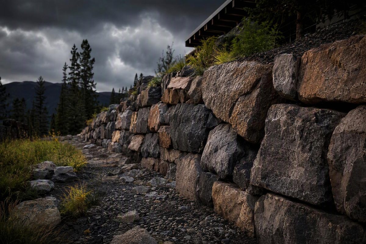
A boulder retaining wall uses the weight and interlock of large stones to resist soil pressure. Engineering references often call it a rockery or rockery wall. The stones are commonly dry-stacked, without mortar or steel connecting them.
If the wall supports soil at a slope steeper than the soil could maintain by itself, it is a retaining structure—not merely landscaping. Its stability depends on the foundation, boulder geometry, wall batter, retained soil, water and loads above the wall.
How a boulder retaining wall works
A retaining rockery behaves broadly as a gravity wall. Its mass and base friction resist sliding, while its base width and backward batter resist overturning. The contacts between individual stones must also prevent local sliding and rotation.
FHWA guidance treats rockeries as modified gravity walls. It identifies lateral earth pressure, surcharge, water and seismic pressure as driving actions; resistance comes from rock weight, inter-rock friction and interaction with the foundation. Design must address sliding, overturning, bearing capacity and global slope stability—not simply the apparent size of the face (FHWA, Chapter 4).
For a triangular active-earth-pressure distribution, the resultant force from the soil’s own weight is proportional to the square of retained height. With the soil and geometry unchanged, doubling the height produces about four times that component of thrust. A successful short garden wall is therefore not a valid detail for a wall twice as high.
Terminology matters. WSDOT describes a rockery’s primary function as protecting an oversteepened but technically stable slope from erosion, although it notes that rockeries behave partly like gravity walls. FHWA also addresses rockeries designed to retain earth. The drawings should identify the intended system rather than using “boulder wall” as a complete specification (WSDOT Design Manual, Chapter 730).
| System | What provides stability | Useful drawing description |
|---|---|---|
| Gravity boulder wall | Boulder mass, batter and foundation friction | Engineered retaining rockery |
| Boulder facing against a stable cut | Stable soil or rock behind the face | Protective rockery or erosion-control facing |
| Boulder-faced reinforced soil | Geogrid-reinforced soil mass; boulders are primarily facing | MSE or reinforced-soil wall with rockery facing |
| Reinforced concrete wall | Concrete stem, footing and reinforcement | See the complete checks for a cantilever retaining wall |
Draw the full section, not only the face
At each change in wall height or ground profile, the documents should show:
- total and exposed wall heights, clearly stating the measurement datum;
- required wall base width and minimum boulder dimensions, including depth perpendicular to the face;
- face batter and required backward inclination of bearing surfaces;
- foundation elevation, leveling course and embedment;
- excavation and temporary back-cut geometry;
- drainage aggregate, filter geotextile and collector pipe;
- retained-soil and structural-fill limits;
- finished grades and surface-water routes at the crest and toe;
- nearby slopes, buildings, driveways, parking areas and construction stockpiles;
- wall ends, corners, steps and transitions; and
- utilities, easements and property lines.
Boulder size cannot be selected from wall height alone. The required section changes with soil strength, foundation bearing resistance, groundwater, backslope, toe slope, earthquake demand and surcharge. The whole slope can fail even when the visible stones do not slide or overturn. FHWA notes that global stability can govern for walls on sloping toes or in previously placed fill, and that the critical slip surface often passes beneath the toe (FHWA, Chapter 4). A heavier face does not necessarily stabilize that deeper failure surface.
A coordinated wall section
This diagram identifies the parts to coordinate; it is not a universal design:
             slope surface or level grade
        swale directs runoff away from crest
     ______________________________________
        retained soil / compacted fill
        | filter geotextile
        | free-draining angular stone
        | o  perforated collector drain → outlet
        |      [boulder]
        |   [boulder]       face battered back
        |[base boulder]
     ___|________________ firm prepared subgrade
          embedment and leveling course
Foundation and embedment
Remove organic material, loose fill and softened soil. The base must bear on competent, reasonably uniform subgrade; otherwise settlement can open joints and rotate individual rocks. Across the wall thickness, the foundation should be level or inclined slightly into the slope, never toward the exposed face.
As reference guidance, FHWA describes a leveling course at least 12 inches (300 mm) thick and nominal embedment of 12 inches at a level toe. It calls for greater embedment where frost, scour, bearing capacity or global stability requires it, and additional toe protection on descending slopes (FHWA, Chapter 5). These are not universal minimums; project conditions and locally adopted requirements control.
Boulder shape and orientation
Suitable wall stone is hard, durable and angular, with roughly rectangular, tabular or cubic geometry. Rounded cobbles and boulders are difficult to seat reliably. Open fractures, foliation and other weak planes can lead to splitting or loss of bearing, especially where freeze-thaw exposure is significant (FHWA, Chapter 5).
Place the longest dimension of each boulder perpendicular to the wall face—into the slope rather than along the elevation. FHWA’s construction guidance generally uses a face batter between 4V:1H and 6V:1H and requires base rocks and bearing surfaces to incline back into the slope. Those proportions are useful references, but the designed section governs.
Bearing and bond
Avoid isolated vertical stacks. Each facing stone should contact at least two stones below and have three bearing points overall: two toward the front and one at the rear. Stagger the joints in an approximate running-bond pattern, without continuous vertical seams or horizontal planes (FHWA, Chapter 6).
Small chink stones can close unavoidable gaps, but they should not provide primary support for an upper boulder. FHWA calls for chinking voids larger than 6 inches (150 mm), while also requiring direct primary bearing between the large rocks (FHWA, Chapter 5).
Drainage is part of the structure
Open face joints do not eliminate the need for drainage. Water escaping through the wall can carry fine soil into its large voids. This piping process can cause ground loss, crest settlement and progressive loss of boulder support.
A robust detail combines:
- Free-draining angular aggregate between the boulders and excavated soil face.
- Filter geotextile separating that aggregate from erodible soil.
- A perforated collector pipe at the low point, connected to a maintainable positive outlet.
- Surface grading or a crest swale that keeps runoff out of the backfill.
FHWA’s reference detail uses a crushed-rock drainage zone at least 12 inches wide, a 4-inch-diameter perforated pipe and nonwoven filter geotextile. It also requires controlled discharge and warns against connecting the drain where a storm system can backflow behind the wall (FHWA, Chapter 5). WSDOT’s September 2024 manual identifies added hydrostatic load as a principal cause of retaining-wall failure and calls for underdrains to reach positive discharge points (WSDOT Design Manual, Chapter 730).
Do not discharge the pipe onto an unprotected slope, neighboring property or the wall toe. Depending on the site, the outlet may require a solid carrier pipe, approved storm connection, energy dissipation or erosion protection.
Put permits and engineering first
Permit thresholds vary by jurisdiction; “four feet” is not a universal exemption. Seattle waives a construction permit only when a wall is no higher than 4 feet from the bottom of the footing to the top, is not on a parcel with an environmentally critical area and will not damage adjoining property or structures. Its rockery designs must either be prepared by a geotechnical engineer or follow the city’s prescriptive standards (Seattle Department of Construction and Inspections).
Apple Valley, Minnesota, requires a permit for a wall over 4 feet or one supporting a surcharge regardless of height, and requires plans signed by a licensed engineer in those cases (City of Apple Valley). These examples show why the local authority must be checked before excavation.
Project-specific geotechnical and structural design should lead the process when a wall is tall, carries surcharge, stands above a descending slope, supports or threatens a structure, encounters weak soil or groundwater, lies in a seismic or scour-prone area, or forms part of a tiered system.
The documents should also establish inspection hold points for the exposed foundation, base course, drainage installation, intermediate lifts and final grading. Because no two boulders have identical geometry, conformity cannot be established from a typical section alone. Stone orientation, actual contacts, drainage continuity and encountered ground conditions must be checked while they remain visible.