
What to Know Before You Specify or Order #6 Reinforcing Bar
For ordering, list size, diameter and length separately, for example: #6, 3/4-inch nominal diameter, 20 feet long.
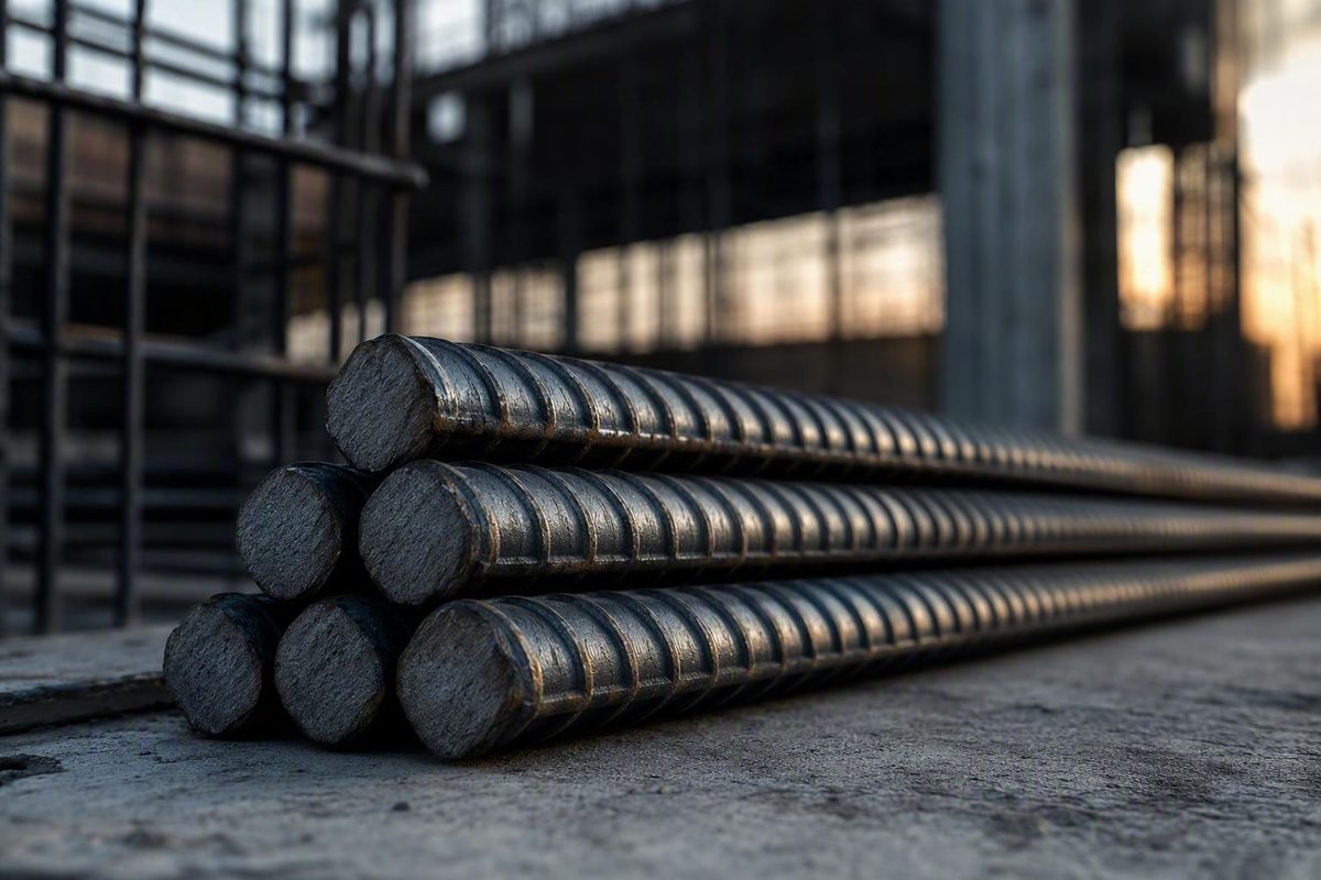
In the U.S. reinforcing-bar system, #6 rebar is a nominal 3/4-inch bar with a nominal cross-sectional area of 0.44 square inch and a nominal unit weight of 1.502 pounds per foot (Harris Supply’s #6 bar data). These stable reference properties help identify the bar and support preliminary quantity and weight calculations.
They do not establish whether #6 rebar belongs in a particular footing, wall, slab, beam, column, or other member. Grade, coating, spacing, cover, splice and development requirements, fabrication, stock length, and applicable material specifications still must be reconciled with the drawings, bar schedule, project specifications, and supplier documentation.
First, resolve what “6 rebar” means
In the U.S. bar-size system, #6 means 6/8 inch, or 3/4 inch, in nominal diameter. The number identifies bar size, not physical length.
That distinction matters when searching supplier and retail catalogs. A Lowe’s result for “6-ft rebar,” for example, is a six-foot-long #4 bar with a 1/2-inch diameter, not size #6 reinforcing bar (Lowe’s six-foot #4 listing). A buyer ordering from an abbreviated description such as “6 rebar” could therefore receive the wrong material.
A U.S. #6 bar can be sold in several lengths. Size, diameter, and length should appear as separate fields on a takeoff or purchase order—for example, “#6, 3/4-inch nominal diameter, 20 feet long.”
The soft-metric designation associated with U.S. #6 rebar is #19, and its nominal diameter is 19.05 millimeters. Soft metric designation gives the familiar U.S. bar a corresponding metric label; it does not create a different physical bar.
Do not confuse that designation with metric No. 6 bar. In the separate metric labeling context presented by Raken, No. 6 is listed at 6.35 millimeters, far smaller than a U.S. #6 or soft-metric #19 bar (Raken’s rebar sizing discussion). When documents, suppliers, or project teams may be using different national systems, confirm the governing standard, nominal diameter, and complete designation rather than relying on “No. 6” alone.
This article addresses identification, preliminary estimating, and purchasing coordination. It does not select reinforcement or provide project-specific structural design.
#6 rebar dimensions and physical properties
The following are nominal reference properties for U.S. #6 reinforcing bar. The supplied sources agree on the #6 values shown below, including the diameter, area, unit weight, and metric conversion (BigRentz rebar-size table).
| Property | U.S. customary value | Metric value |
|---|---|---|
| U.S. bar designation | #6 | — |
| Soft-metric designation | — | #19 |
| Nominal diameter | 0.750 in | 19.05 mm |
| Nominal cross-sectional area | 0.44 in² | 284 mm² |
| Nominal unit weight or mass | 1.502 lb/ft | approximately 2.24 kg/m |
These values describe different characteristics:
- Diameter identifies the nominal bar size across its cross section. For #6 rebar, that reference diameter is 0.750 inch.
- Cross-sectional area is the nominal area of steel in a cut perpendicular to the bar’s length. Reinforcement calculations that specify steel area use this property.
- Unit weight states how much a given length of bar weighs. It supports takeoffs, order-weight estimates, transportation planning, and material handling coordination.
The properties are related, but they are not interchangeable. A requirement expressed as steel area cannot be replaced with a weight value without the relevant calculation. Likewise, knowing the diameter does not establish the number of bars, their spacing, their arrangement, or the total reinforcement area in a member.
These are nominal properties, not a promise that a casual measurement across the ribs of every individual bar will read exactly 0.750 inch. Product acceptance depends on the governing material specification, permitted tolerances, markings, tags, and supporting documentation.
The evidence supplied for this article is consistent on the #6 values, although some secondary charts contain inconsistencies in rows for other bar sizes. The evidence pack does not include the controlling text of a primary ASTM, CRSI, or ACI publication. For project use, verify dimensions, tolerances, markings, and product compliance against the current documents named in the project specifications rather than treating a commercial chart as the final authority.
How much does a stick of #6 rebar weigh?
For a preliminary estimate of straight, unmodified #6 bar, use:
Straight-bar weight = total linear feet × 1.502 lb/ft
Applying the published nominal unit weight produces these results:
| Straight bar length | Calculation | Nominal weight |
|---|---|---|
| 20 ft | 20 × 1.502 | 30.04 lb |
| 30 ft | 30 × 1.502 | 45.06 lb |
| 40 ft | 40 × 1.502 | 60.08 lb |
| 60 ft | 60 × 1.502 | 90.12 lb |
The 1.502-pound-per-foot basis and the resulting straight-bar arithmetic are suitable for preliminary review, not reinforcement design or procurement approval (ToolGrit’s #6 property row and calculator limitations).
Hypothetical order-weight example
Assume an estimator identifies 48 straight #6 bars at 20 feet each in a project takeoff.
- Calculate total linear footage:
48 bars × 20 ft = 960 linear ft
- Apply the nominal unit weight:
960 linear ft × 1.502 lb/ft = 1,441.92 lb
The preliminary nominal weight is therefore approximately 1,442 pounds.
That result estimates the weight of the listed straight bars. It is not necessarily the final purchased quantity, fabricated weight, delivered weight, or shipping weight. A complete takeoff may also need to account for:
- Lap-splice material
- Bends and hooks
- Dowels and starters
- Cutting losses and unusable offcuts
- Waste allowances
- Staggered splices
- Chairs, supports, ties, and other accessories
- Multiple reinforcement layers
- Stock-length optimization
- Couplers and other connection details
- Fabricated shapes that cannot be represented as full straight sticks
Installed linear footage and purchased linear footage should be kept separate. Bars cut from fixed stock lengths can leave substantial offcuts; conversely, a coordinated cutting schedule may allow an offcut from one location to be used elsewhere. Estimators should show installed quantity, stock quantity, waste, and accessories as distinct lines rather than concealing them within one unexplained allowance.
Available lengths are supplier-specific. Harris Supply describes 20- and 30-foot bars as standard offerings and also advertises 40- and 60-foot cuts, but that assortment is a supplier offering rather than a universal length standard (Harris Supply’s stock and length chart). Before basing a cutting plan on a particular stock length, confirm that the required size, grade, coating, quantity, and fabrication are available in that length.
Where #6 rebar is commonly encountered
Supplier and construction references characterize #6 as a medium-diameter bar associated with heavier concrete work, rather than as the default reinforcement for every residential slab. That description is a commercial and practical characterization, not a standardized design classification.
Supplier-described applications include:
- Larger foundations and foundation repairs
- Retaining walls
- Tilt-up wall panels
- Caissons
- Precast concrete or masonry products
- Beams and columns
- Overhead slabs
- Heavy mat slabs
- Parking structures
- Bridge slabs
- Roadway dowels
- Equipment pads
- Selected road and highway work
These examples describe places where designers, estimators, contractors, or buyers may encounter #6 bars. They are not recommendations to use that size in every listed application. A retaining wall can require different reinforcement in different locations, and two foundations with similar overall dimensions may have different reinforcement because their loads, soil conditions, geometry, exposure, and detailing differ.
Project category alone is not a design criterion. A relatively small but heavily loaded member may require substantial reinforcement, while a larger nonstructural placement may not. Reinforcement selection can depend on:
- Applied loads and load combinations
- Member dimensions and structural behavior
- Concrete strength
- Required steel area
- Bar spacing and arrangement
- Clear cover
- Exposure conditions
- Bar grade and coating
- Development and splice requirements
- Seismic detailing
- Adopted code and local amendments
- Constructability and congestion
- Structural drawings, details, and schedules
An application list can explain why #6 appears on a quote or reinforcement schedule. It cannot establish that the bar is required, sufficient, or suitable for a particular member.
Grade, coating, and identification are separate from bar size
The designation #6 identifies nominal size only. It does not specify grade, material specification, coating, corrosion resistance, steel chemistry, or weldability.
Grade 60 is prominent in the supplied retail listings. McCoy’s, for example, identifies a 3/4-inch-diameter, 20-foot #6 bar as Grade 60 and describes that grade as having a minimum yield strength of 60 thousand pounds per square inch, or 60 ksi, under normal conditions (McCoy’s Grade 60 product listing). The grade number communicates a strength classification; it is not another statement of bar diameter.
The supplied references also discuss Grades 40, 75, 80, and 100. Their availability does not make them interchangeable. The required grade must come from the project documents and applicable material specification.
The same principle applies to coating and product form. Commercial sources describe categories including:
- Uncoated or “black” rebar
- Epoxy-coated rebar
- Other specialty reinforcing products
- Straight, coiled, or fabricated material
Two bars being size #6 does not establish equivalent compliance, corrosion resistance, or suitability for the same exposure. A required coating is part of the product identity, not merely a purchasing preference.
Bar markings may identify the producing mill, bar size, steel type, and grade, according to the supplied rebar marking guide (DOZR’s rebar size and marking guide). Markings should be checked together with bundle tags, purchase documents, the applicable ASTM designation, mill certification, coating documentation, and the project specification. A field marking check is one part of verification, not a complete material-acceptance procedure.
Weldability requires particular caution. It must not be inferred from the #6 designation or from a generic description such as “steel rebar.” A retailer’s statement that one steel item is weldable does not prove that a different #6 reinforcing bar may be welded.
A practical purchasing and receiving sequence is:
- Read the structural drawings, bar schedule, and material specifications.
- Confirm size, grade, coating, and required fabrication.
- Inspect bar markings and bundle tags.
- Request the applicable ASTM designation and mill certification.
- Compare delivered documentation with the purchase order.
- Resolve inconsistencies before accepting or placing the material.
Do not assume that every #6 bar complies with one particular ASTM specification. The supplied retail descriptions do not provide enough certification evidence to support that conclusion.
Estimating quantity without mistaking arithmetic for design
The engineer or construction documents establish reinforcement requirements. The estimator converts those requirements into bar counts, installed linear footage, stock pieces, fabricated shapes, and estimated weight.
At minimum, a preliminary grid takeoff needs:
- Member length and width
- Specified center-to-center spacing
- Edge clearance or bar-position information
- Number of reinforcement directions
- Number of layers or mats
- Required stock lengths
- Bar size and grade
- Required bends, hooks, dowels, and other shapes
- Splice and development details
- Openings, blockouts, thickened areas, and interruptions
A basic workflow is:
- Determine how many bars run in each direction.
- Determine the length of each bar or fabricated segment.
- Add the bars from both directions; do not multiply the directional counts.
- Calculate intersections separately if that quantity is needed.
- Total the installed linear feet.
- Develop a cutting plan using available stock lengths.
- Add only the allowances supported by the drawings or estimating policy.
- Multiply the applicable #6 linear footage by 1.502 pounds per foot.
Hypothetical two-way-grid example
This example demonstrates arithmetic only. Assume a rectangular member measuring 10 feet by 8 feet, with one two-way reinforcement layer. For illustration, the project documents have already specified 12-inch centers and bar centerlines 6 inches from each edge. Assume straight bars and ignore laps, openings, hooks, and other details.
Bars parallel to the 10-foot side
The bars are distributed across the 8-foot width:
- Distance between the first and last bar centerlines:
8 ft − 0.5 ft − 0.5 ft = 7 ft - Seven 1-foot spaces require 8 bars.
- Length of each bar after the 6-inch offsets at both ends:
10 ft − 1 ft = 9 ft - Linear footage:
8 bars × 9 ft = 72 ft
Bars parallel to the 8-foot side
The bars are distributed across the 10-foot width:
- Distance between the first and last bar centerlines:
10 ft − 0.5 ft − 0.5 ft = 9 ft - Nine 1-foot spaces require 10 bars.
- Length of each bar:
8 ft − 1 ft = 7 ft - Linear footage:
10 bars × 7 ft = 70 ft
Grid totals
| Quantity | Result |
|---|---|
| Bars parallel to 10-ft side | 8 |
| Bars parallel to 8-ft side | 10 |
| Total bars | 18 |
| Grid intersections | 8 × 10 = 80 |
| Installed linear footage | 72 + 70 = 142 ft |
| Nominal installed weight | 142 × 1.502 = 213.28 lb |
These quantities follow directly from the stated hypothetical dimensions and the published #6 unit weight. The grid contains 18 bars, not 80; the number 80 represents intersections. Confusing intersections with bar count would materially overstate the takeoff.
Stock-length conversion requires another step. Dividing total footage by a 20-foot stock length gives:
142 ft ÷ 20 ft = 7.1
Rounding that result up suggests eight stock bars, but it does not prove that eight bars can produce the required set of eight 9-foot pieces and ten 7-foot pieces.
One workable preliminary cutting plan uses nine 20-foot bars:
- Eight stock bars each produce one 9-foot piece and one 7-foot piece.
- One stock bar produces the remaining two 7-foot pieces.
That plan purchases 180 feet and leaves 38 feet of offcut before any approved reuse:
180 ft − 142 ft = 38 ft
The corresponding nominal purchased weight is:
180 ft × 1.502 lb/ft = 270.36 lb
This example shows why dividing total footage by stock length is not a complete cutting schedule. It also shows why assuming every counted bar runs the full member length can overstate or understate a real fabricated layout, depending on bar direction, openings, required splices, available stock lengths, and other interruptions.
Some general calculator pages mention spacing ranges such as 18 to 24 inches on center. That is not a #6 design prescription. Spacing must come from the project requirements. Calculator output is a preliminary quantity check—not structural design, code verification, procurement authorization, shop-drawing approval, or permission to place concrete.
Why there is no universal lap, development, or embedment length
A lap splice overlaps two reinforcing bars so they can function as a continuous run. Development length is the length required to transfer force between reinforcement and the surrounding concrete. Post-installed adhesive embedment concerns a bar installed into hardened concrete using a selected adhesive system.
The three concepts relate to force transfer, but they are not interchangeable.
A simplified diameter-multiplier formula is sometimes shown as:
Illustrative lap length = bar diameter × multiplier
For a nominal 0.75-inch #6 bar:
0.75 in × 40 = 30 in0.75 in × 60 = 45 in
These are arithmetic illustrations only. They are not universal or automatically code-compliant lap lengths. The calculator presenting the 40- and 60-diameter factors also directs users to apply the engineering specification governing the work (vCalc’s lapping formula and qualification).
A proper lap or development requirement may depend on:
- Lap-splice class
- Tension or compression condition
- Concrete type and specified strength
- Reinforcing-steel yield strength
- Bar coating
- Bar spacing
- Clear cover
- Confinement
- Reinforcement provided relative to reinforcement required
- Splice location and percentage of bars spliced
- Seismic design category and detailing
- Bar position
- Hooks or mechanical connections
- The selected adhesive system for post-installed work
- Conditions and limitations in approved product documentation
These variables help explain why calculators may produce different results for what appears to be the same bar. If their assumptions differ, their outputs can differ as well.
Post-installed reinforcement introduces product-specific conditions. Simpson Strong-Tie’s calculator separates lap-splice and development applications and requests inputs including concrete strength, bar yield strength, coating, spacing, cover, splice class, and seismic information (Simpson Strong-Tie’s development-length calculator).
Bar size alone cannot establish:
- Lap-splice length
- Tension or compression development length
- Hook development
- Drill depth
- Adhesive embedment
- Edge distance
- Clear cover
- Bar spacing
Use the structural details, adopted code, engineer-of-record direction, and approved product documentation. If those sources conflict or appear incomplete, resolve the issue before fabrication or installation rather than selecting a convenient multiplier.
Price snapshots and an ordering checklist
Diameter, area, and nominal unit weight are stable reference properties. Price, inventory, freight, available lengths, fabrication charges, and minimum orders are volatile commercial information.
The evidence supplied for this article does not provide a reliable capture date for the following retailer pages. They should therefore be treated as undated historical listing examples, not current quotes:
- McCoy’s displayed $18.39 for a 20-foot, 3/4-inch, Grade 60 #6 bar, with inventory associated with the displayed San Marcos location (McCoy’s listing).
- LA Steelworks displayed $19.88 for a Grade 60 #6 listing with 20-, 30-, and 40-foot selections, but the page did not establish which length the displayed price covered and showed the item as sold out (LA Steelworks listing).
The two prices should not be averaged. Neither is evidence of a current, typical, or national #6 rebar price.
Before comparing quotes, confirm:
- Whether the price is per bar, per hundredweight, per ton, or another unit
- Exact bar length
- Bar size and nominal diameter
- Grade
- Applicable ASTM specification
- Coating or finish
- Straight versus fabricated material
- Cutting and bending charges
- Quantity breaks and minimum order
- Current location-specific inventory
- Freight or delivery charges
- Fuel or handling surcharges
- Unloading requirements and site access
- Return and cancellation conditions
- Quote expiration
- Taxes and other commercial terms
Long pieces also affect delivery and handling coordination. A project buying 20-, 30-, 40-, or 60-foot bars should verify that the selected length is compatible with the supplier’s transportation, unloading, storage, and fabrication arrangements. The appropriate plan depends on the site, equipment, supplier, and project requirements.
A final purchase review should cover:
- [ ] U.S. bar size: #6
- [ ] Nominal diameter: 3/4 inch
- [ ] Required grade
- [ ] Applicable ASTM specification
- [ ] Required bar markings
- [ ] Bundle tags
- [ ] Mill certification
- [ ] Required coating or finish
- [ ] Straight or fabricated shape
- [ ] Bar and stock lengths
- [ ] Piece count
- [ ] Installed linear footage
- [ ] Total estimated weight
- [ ] Laps and development details
- [ ] Bends, hooks, dowels, and couplers
- [ ] Cutting plan and waste allowance
- [ ] Delivery access and unloading constraints
- [ ] Current supplier stock and quote terms
Resolve discrepancies among the drawings, bar schedule, supplier description, bundle tags, and mill certification before purchase or placement. A matching diameter does not correct a mismatch in grade, coating, specification, or fabrication.
Is #6 rebar the same as 3/4-inch rebar?
In the U.S. bar-size system, yes: #6 rebar has a nominal diameter of 6/8 inch, which equals 3/4 inch. Context still matters because “3/4-inch steel bar” does not by itself identify reinforcing-bar grade, deformation pattern, coating, specification, or certification.
How much does a 20-foot piece of #6 rebar weigh?
Using the nominal unit weight:
20 ft × 1.502 lb/ft = 30.04 lb
A straight 20-foot piece therefore weighs approximately 30.04 pounds nominally. That is a preliminary estimating value, not a final order weight incorporating fabrication, laps, waste, accessories, or other procurement allowances.
What is the metric equivalent of U.S. #6 rebar?
The soft-metric designation is #19, and the nominal diameter is 19.05 millimeters. Do not confuse it with metric No. 6 bar, which belongs to a different designation system and is much smaller.
What does Grade 60 mean on a #6 rebar listing?
Grade 60 identifies a minimum yield-strength classification of 60 ksi; it does not describe bar diameter. A product can be both #6 in size and Grade 60 in strength classification because those are separate attributes.
Grade also does not establish coating, applicable ASTM specification, or weldability. Confirm those attributes through the project requirements, markings, bundle tags, and mill documentation.
What lap length or spacing should be used for #6 rebar?
There is no universal lap length or spacing determined solely by the #6 designation. Spacing comes from the structural design and project documents. Lap and development requirements can vary with concrete strength and type, steel grade, coating, cover, spacing, confinement, splice class, tension or compression conditions, seismic detailing, and other project inputs.
The essential distinction is straightforward: #6 describes a nominal 3/4-inch U.S. reinforcing-bar size, not a six-foot length. Its nominal area is 0.44 square inch, and its nominal weight is 1.502 pounds per foot. Those values support identification and preliminary estimating; they do not design reinforcement.
Before specification, purchase, fabrication, or placement, reconcile the drawings and bar schedule with the required grade, coating, applicable specification, mill documentation, splice and development details, stock lengths, current supplier terms, and qualified engineering direction.